Ultra-high Density MTP/MPO System In Data Center

Today’s data center and telecommunications environments heavily depend on the foundations of the optical network communicating, transmitting, and protecting the data upon which your business relies. So what makes your optical network different to your competitor’s network? How can the design and performance of your data / telecom environment contribute more to the bottom-line, while at the same time be mindful of reliability and uptime. It’s achievable with Fiberstore Ultra High Density Solutions, industry engineered pre-terminated optical cabling systems that take your data/telecommunications environments beyond the next level.

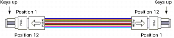
The fiber system has a higher and higher demand on fiber optic connectors with changes from single mode fiber to multimode fiber, from 10G to 40G, 100G. Ethernet transmission of 40G and 100G also becomes the developing trend in data center cabling system. Traditional connectors are more and more difficult to achieve Multi-Fiber and High-performance. According to the International standard port in the Ethernet transmission of 40G and 100G.

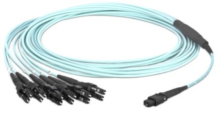
FS develops a high density MTP/MPO cabling solution with its constant innovation in the field. The MTP MPO is a standard mini, high-density connector, equipped with Multi-core ribbon fiber, which makes the connection stable and reliable. The connection and testing of high density connector with ribbon cable are finished in factory, so that it can be plugged and played with the equipments on site directly, and support the rapid deployment at users’ data center, which makes MTP/MPO cabling system become ideal solution with growing demands on high-capacity cabling data center. Simple installation, fast contruction, compact design, high precision, plugs and play, etc.

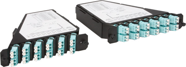
FS offers a wide range of high density patch panels and fiber enclosures that will help free up rack space. Our 24-fiber MTP cabling systems provide at least double the density in enclosures and allow for fewer cable pathways than legacy 12-fiber cabling. And high-capacity cable management solutions make it easy to route additional networks while improving overhead space and access. Now the following is the introduce of the High Density MTP/MPO cassettes.

The High Density MTP/MPO cassette system is compatible with a 1U 5 slot modular chassis scaling up to 120 discrete fibres in a 1U space. High Density MTP MPO Cassette provide secure transition between MTP/MPO and LC or SC discreet connectors. They are used to interconnect MTP/MPO backbones with LC or SC patching. Modular systems allow for rapid deployment of high density data center infrastructure as well as improved troubleshooting and reconfiguration during moves, adds and changes.

With a rear bottom tray that slides inward for easy access to the connectivity while the enclosures are stacked on top of each other, FS offers best in class accessibility compared to any other high-density fiber enclosure on the market. In the out position, the rear tray acts as a cable partition between stacked enclosures. Low-Loss Plug and Play Modules are also easily inserted or removed from either the front or rear of the enclosure and the visually appealing easy-open magnetic door eliminates harmful pinch points and offers high-visibility drop-down labeling.

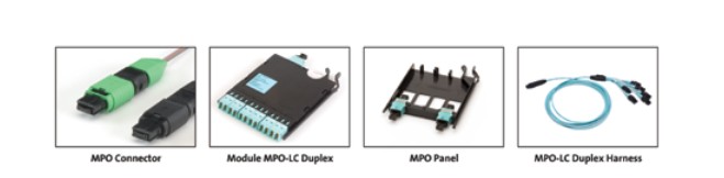
Available in OM4 multimode and singlemode, the ultra-slim LC-to-MTP Low-Loss Plug and Play modules offer the industry’s lowest loss performance of 0.35dB for flexible fiber channels. Fully ready to support 40 and 100 gigabit applications, FS low-loss 0.2dB MTP pass-through adapters are available in 2, 4 and 6-port designs and they are offered in both aligned and opposed key orientation to accommodate all polarity methods. Unlike other fiber solutions on the market, FS also supports 12-fiber LC pass-through adapter plates for current 10 gigabit Ethernet or Fibre Channel SAN applications.

“As today’s high-density data centers migrate from 10 to 40 and 100 gigabit speeds, they require low-loss fiber connectivity to support multiple mated connections for flexible patching options over a wide range of distances and configurations while remaining within link loss budgets. At the same time, these connections need to be easily accessed and managed to quickly and effectively make changes,” explains Charlie Maynard, Fiber Optic Product Manager at Siemon’s global headquarters. “With superior best-in-class features, our new Ultra High Density Fiber System is uniquely positioned to overcome current and future fiber connectivity challenges.”

The MPO and MTP Connectors For Plug-n-Play Systems

Today’s Data Centers are critical to the IT infrastructure of most large enterprises. Thanks to their quick-connect design, Plug-n-Play (PnP) fiber systems are becoming the prevalent choice for modern Data Centers. With Plug-n-Play, installation is fast and easy, and network downtime is minimized during expansions, scheduled maintenance, and emergency restoration procedures. The mainstays of modern PnP Systems are the relatively new multi-fiber connectors that allow for the interconnecting of several fibers at a time in a very dense footprint.

MPO stands for “Multi-Fiber Push On” and was originally designed by NTT. The design is based on the MT (mechanical transfer) ferrule. It is defined by the Telecommunications Industry Association’s (TIA) Fiber Optic Connector Intermateability (FOCIS 5) document, the TIA 604-5B Standard, and internationally by the IEC-61754-7 standard. The MTP connector is the “latest-generation MPO” connector with flaws fixed and features added to improve reliability and performance. Some improvements include lower insertion loss, the possibility of restoring the tip by polishing it, and the use of interferometers for better quality control(2). The MTP’s superior performance allows for optical insertion losses of 0.5dB or less. Figure 1 shows superior mechanical test performance results, another of the clear advantages of the MTP connector.

MTP

Both connectors are intermateable, meaning it is possible to connect an MTP to an MPO and vice-versa. Each connector will support some fibers, the most common being 12, while some versions are available with 24 fibers or even more. However, one should consider whether the space savings and easy connection convenience provided by connectors terminating more than 12 fibers will potentially impact reliability. Servicing a single fiber that may have been damaged will require the disconnecting of all other fiber channels linked through that connector. MTP and MPO connectors have guide pins to ensure proper fiber alignment and minimize optical insertion loss. These pins are present on the “male” connectors only. However, MTP connectors can be easily converted from “male” to “female” by removing the pins and, conversely, “female” to “male” by adding the pins.

Fiberstore has announced the release of a full suite of MPO MTP products designed to support the next generation of high-density fiber networks in data centers. The new product group includes MPO/MTP patch cables, trunk assemblies, fan-out assemblies, and related distribution hardware.

Fiberstore series rack-mounted patch panel is designed to manage and house easy-plug MTP/MPO to LC fiber cassette modules, for connecting plug-and-play pre-terminated high-density MTP / MPO Fiber cabling system. This solution contributes to greater network availability that is especially suitable for SAN, LAN, and Data Center applications. Each easy-plug MPO MTP cassette is accommodated with 12/24-fiber MTP / MPO-based fiber assemblies, and pre-loaded with LC adapters in different fiber modes for your choices.

FS High Fiber Count Plug-and-Play Trunks provide the backbone cabling for the TrueNet Plug-and-Play system. These high-count fiber trunk cables come pre-terminated with high-density MTP/MPO connectors on both ends and provide an easy and efficient way to pull large numbers of fibers at one time to help in the rapid deployment of the TrueNet Plug-and-Play system either in the data center or Local Area Network (LAN). Each fiber trunk cable has custom breakouts designed to work with ADC TrueNet Plug-and-Play connectivity. The FS High Fiber Count Trunks can simply be plugged into any plug-and-play cassette in the optical distribution frame or fiber enclosure which eliminates the need for on-site fiber termination and preparation.

Data Centers host expensive equipment and process very sensitive information for networks that must be always available. This level of reliability imposes stringent requirements on a Data Center’s infrastructure. A Data Center manager must be able to quickly perform adds, moves, and changes, as well as restorations in case of an outage. A very good analogy is a racecar making a pit stop and being serviced as quickly as possible.  In a data center hosting mission-critical applications, every second also counts. Therefore, the ability to quickly connect new equipment or service existing equipment is crucial. To accomplish this “quick-connect” capability, the fiber optics industry formulated a new de facto fiber standard, sometimes referred to as “Plug-n-Play” (PnP), based on an existing philosophy already adopted by many vendors in the computer industry. PnP systems are based on trunk cables, cassettes, harnesses, etc, which are comprised of pre-connectorized fiber optics elements.

Another solution for achieving quick connection is the use of multi-fiber connectors. By connecting several fibers at once, the installer or administrator saves a considerable amount of time. Since the time to connect a 12-fiber MTP connector is the same as to connect a single fiber connector (also called a discrete connector) one can make the same number of connections in roughly 1/12th the time. A common data center can easily reach 1,000 fiber terminations or more. Consequently, the time savings can be significant. Because PnP systems also allow for pre-engineered solutions, it is possible to determine cable lengths during the planning phase and, therefore, order only what is needed. This not only helps save money on fiber infrastructure but also helps to alleviate cable congestion under the raised floor. Since one of the main issues data center administrators have to face is cooling increasingly dense computing infrastructure, the use of a pre-engineered PnP system also helps to optimize cold air distribution. As previously mentioned, the building blocks of a PnP system are cable trunks, harnesses, PnP modules (often called cassettes), patch cords (also called jumpers), and accessories such as patch panels and enclosures. Multi-fiber connectors are present in virtually all these elements, and, along with small form factor connectors such as the LC, allow for reducing the “real estate footprint” in the data center. A solution using MTP and small form factor connectors can be almost twice as dense as a solution using previous-generation optical connectors. Therefore, more floor space is left available for mission-critical equipment such as switches, routers, servers, and storage.

MTP Cabling Options for 40 Gbps Parallel Optical Modules

As previously mentioned, in 2010 IEEE 802.3ba approved the 40GBASE-SR4 physical-medium-dependent (PMD) multimode parallel optic solution, which uses eight fibers to transmit four duplex channels each at 10 Gigabit Ethernet. As shown in Figure 11, each transceiver transmits over four fibers and also receives transmissions over four fibers.

Also as previously mentioned, parallel optics does require a change from traditional cabling methods, which requires learning and so creates an incentive to move to the bidirectional solution at 40 Gigabit Ethernet. The main advantage of the parallel optics transceiver over the bidirectional transceiver at 40 Gigabit Ethernet is reach. For example, if you cable your data center with OM3 fiber at 10 Gigabit Ethernet, you can support distances up to 300m. Then if you move to 40 Gigabit Ethernet, you can support the same 300m distance with the same OM3 fiber and a 40GBASE-CSR4 transceiver. However, if your cabling distances do not justify the extra distance capability, then the bidirectional solution would be used (Figure 11).

40G Base

The dilemma is that MTP cable assemblies, which have been used for more than a decade for cabling in the data center, are built on 12-fiber position connectors. Thus, each link has four unused fibers. There are several basic cabling options for parallel optics connectivity. One approach is to ignore the unused fibers and continue to deploy 12 fibers. Another approach is to use a conversion device to convert two 12-fiber links into three 8-fiber links. Three solutions exist (summarized in Table 7 and Figure 12).

• Solution 1: The no-conversion scenario retains the whole 12-fiber based cabling system, but 33 percent of the fiber is not used. Additional cost is associated with the purchase of additional fiber, and your system includes unused fiber.
• Solution 2: This solution uses conversion modules to convert the unused fibers into useable optical links. For every two 12-fiber MTP connectors in the backbone cable, you can create three 8-fiber links. There is an additional cost for the additional MTP connectivity, but that is offset by the cost savings from 100 percent fiber utilization in the structured cabling. When you reuse existing deployed MTP cabling, you gain great value when you use the conversion module to use all previously deployed fiber, and you eliminate the cost of having to deploy additional cabling.
• Solution 3: This scenario uses standard MTP Cassette with a conversion assembly (two 12-fiber MTP connectors on one end going to three 8-fiber MTP connectors on the other end). This approach does not add any connectivity to the link, and it achieves full fiber utilization. However, although this approach may appear attractive, it involves considerable cabling challenges. For example, if you need only two 40-Gbps connections to a piece of equipment, what do you do with that third 8-fiber MTP connection? What if the 40-Gbps ports are in different chassis blades or completely different chassis switches? The result will be long assemblies, which will be difficult to manage in an organized way. For this reason, Solution 3 is expected to be the least desirable and so the least deployed method.

Table 7. Three Cabling Solutions for 40-Gbps Connectivity

40-Gbps Connectivity

Figure 12. Cabling Solutions for 40-Gbps Connectivity

Cabling Solutions

Fiberstore offers components to build all three solutions. However, Fiberstore suggests implementation of the conversion module solution, especially if you are using previously installed MTP trunks. This solution allows 100 percent fiber utilization while maintaining any port-to-any port patching. If you are installing all new cabling, then you could consider the no-conversion solution, assuming that the cable raceway is not a concern. Typically, the conversion harness is deployed only in specific applications, such as at the ToR switch, where 40-Gbps ports are in a close cluster and patching between blades in a chassis switch is not required.

When directly connecting a parallel optics 40 Gigabit Ethernet transceiver to another 40 Gigabit Ethernet transceiver, a Type-B pinless-pinless MTP jumper should be used. As shown in Figure 13, a Type-B MTP jumper assembly, as defined in TIA-568-C.3, has the blue fiber 1 assembled in connector position 1 on one end of the assembly, and this same fiber assembled in connector position 12 on the other end of the assembly. This reverse fiber positioning allows the signal to flow from transmission on one end of the link to reception on the other end.

Figure 13. Type-B Array Patch Cord (per TIA-568-C.3)

Array Patch Cord

This type of direct connectivity is suggested only within a given row of cabinets. The jumper assembly is tested only to the requirements of an interconnect cable, as defined in ANSI/ICEA S-83-596-2001. It has less robustness (less tensile strength, less crush and impact resistance, etc.) than a distribution-style cable, which would be used for structured cabling trunks.

Similar to the bidirectional cabling approach, the most basic structured cabling solution is an interconnect. The only difference between an interconnect solution and parallel optics is that the connector type of the patch panels instead is MTP. Figure 15 shows several interconnect link scenarios with various patch-panel options. As previously discussed, the 2×3 conversion modules, depicted in Figure 15a, allow 100 percent fiber utilization and constitute the most commonly deployed method. Another advantage of the conversion module is reduced jumper complexity. Notice that a G jumper, which has a Type-B polarity and is pinless, is used to directly connect two parallel optics transceivers. That same jumper is used on both ends of the interconnect link, thus eliminating concerns about correct pinning.

In Figure 15b, the same trunk is used, but the jumper type is now labeled F. In the bill-of-materials (BoM) shown in Table 8, you can see that an F jumper still has a Type-B polarity, but on one end the MTP is pinned and on the other end a pinless MTP is used. Thus, when you install the jumper, you would install the pinned end in the patch panel, and you would install the pinless end in the electronics. However, because of the pinning, this same jumper could not be used to make a direct connection between two ports. Hence, you can see the advantages of the conversion modules, which both use all the fiber and allow a single-jumper solution.

However, notice in Figure 16b that this is not the case for a non-conversion cabling scenario, in which standard MTP patch panels are deployed. Here the patch cords at the electronics are pinless (into the electronics) to pinned (into the patch panel), although the patch cords at the cross-connect are both pinned going into the patch panel. Thus, for a direct-connect, interconnect, and cross-connect cabling scenario, three different pinned jumpers are required.

An alternative approach is to install pinned MTP trunks in the structured cabling, but this approach can be used mainly in new installations because the traditional MTP trunks installed over the past decade have been pinless.

Structured cabling using an MTP cabling infrastructure can be used with current 10 Gigabit Ethernet environments while maintaining investment protection for 40-Gbps environments and beyond. With the new 40 Gigabit Ethernet bidirectional transceivers, no changes to the cabling infrastructure are required when transitioning from 10 to 40 Gigabit Ethernet. Extended 40 Gigabit Ethernet link distances, which match the distances at 10 Gigabit Ethernet, can be achieved by converting to parallel optics transceivers.

These transceivers require a change in traditional cabling practices. However, if structured cabling has been implemented with MTP-based trunk cables, then making the conversion is as simple as swapping the patch panels. Thus, the existing MTP-LC modules that were used in the two-fiber serial transmission would be replaced with MTP conversion modules for parallel optics.

Plug-and-Play MPO Solutions in Fiber Cabling

As enterprises implement more fiber optic cabling to support bandwidth and storage requirements in the data center and backbone infrastructures, fiber termination methods are under intense scrutiny. Data center managers need to understand the key performance, installation, management, and cost considerations surrounding primary fiber termination methods. Each method has its pros and cons, and the need has never been greater for comprehensive information to help data center managers make the right choice for their environment. In this white paper, you will learn about the pros and cons of the following fiber termination methods:

  • Preterminated Plug-and-Play MPO Solutions
  • Factory-Terminated Pigtails with Splicing
  • Field Termination

The MPO connector is a high-density, multi-fiber connector that typically terminates 12 fibers in one connector approximately the same size as one SC-style fiber connector. MPO plug-and-play cassettes include an MPO interface on one side broken out to 12 individual fiber interfaces on the other side. These cassettes can be deployed in an optical distribution frame for higher-density applications or in fiber panels to connect the main distribution area (MDA) to the equipment distribution area (EDA) in the data center. Plug-and-play trunk cables are round 12-fiber cables that are pre-terminated in the factory with MPO connectors on both ends. These trunk cables are purchased in predetermined lengths and are typically easier to manage than traditional ribbon cables. They can be quickly connected to the MPO plug-and-play cassettes at the cross-connect or interconnect in the MDA, EDA, or other areas of the data center. This method eliminates the need for on-site fiber termination and splicing. Consequently, customers can rapidly complete fiber connections in high-density applications.

MPO-Cassettes

Advantages of Plug-and-play MPO Solutions

  • Reduced Labor Cost

Less time is required for plug-and-play installation vs. splicing or field termination. Less expertise and resources are required of installation staff.

  • Enhanced Performance

MPO connectors are factory terminated and tested in a clean environment with comprehensive quality control processes and documented test results that correspond to serial numbers stamped on each assembly.

  • Better Manageability and Density

MPO Cassette offers the highest density for fiber connections, maximizing space savings in the data center. They are easily deployed in a cross-connect scenario for better cabling management.

  • Better Prepared for Beyond 10-Gigabit

40G and 100G speeds on multimode fiber will likely require parallel optics where data is transmitted and received over multiple fibers. MPO connectors are more prepared for this technology because they already encompass multiple fibers.

Disadvantages of Plug-and-play MPO Solutions

  • Increased Material Cost

Plug-and-play MPO solutions are typically more expensive than other options.

  • Higher Return Loss and Insertion Loss

The additional mated pair increases the return loss and insertion loss. Insertion link loss with MPO solutions can account for an additional 0.5dB per cassette, requiring careful planning of the loss budget.

  • Limited Access to Individual Circuits

With 12-fiber MPO trunk cable, individual circuit access to backbone cabling is limited. However, when used in a cross-connect scenario, individual circuits should not need to be accessed once installed.

  • Predetermined Lengths Required

MPO trunk cables are made to order in predetermined lengths, so lengths and lead time must be part of the planning process. In addition, measurements need to be exact, or slack storage will be required.

fiber trunk cable

FS.com MPO Cassette provides a seamless plug-and-play structured cabling solution especially suitable for high-density data center environments. By integrating with the FS.com Plug-and-play rackmount enclosure, it connects the MPO interfaces on the backbone trunk cable to the generic LC interface that will directly link to the equipment.

The cassette is designed with a user-friendly snap-in modular style, pre-installed with factory-terminated and factory-tested 12 or 24-fiber MPO to LC assembly with assured best performance on optical loss. The convenient plug-and-play feature offers a flexible, quick-deployment solution with maximum reliability and durability, which offers a simple and efficient choice in optimizing your network system.

FS.com manufactures a wide range of MTP/MPO products including MPO/MTP fiber cables, MTP/MPO Harness Cable, MTP/MPO trunk cable, and MTP/MPO cassettes. Multi-fiber ferrule connections are used in high-density backplane and Printed Circuit Board (PCB) applications in data and telecommunications systems. High-density MTP/MPO trunk cables with up to 144 fibers. The MPO fiber cable connector offers up to 12 times the density of standard connectors, providing significant space and cost savings.

40/100G With OM3 and OM4 In MPO Cabling Data Center

With the continued requirement for expansion and scalability in the data center, cabling infrastructures must provide reliability, manageability, and flexibility. Deployment of an optical connectivity solution allows for an infrastructure that meets these requirements for current and future data rates. A key factor when choosing the type of optical connectivity is scalability. Scalability refers to not only the physical expansion of the data center concerning additional servers, switches, or storage devices but also to the scalability of the infrastructure to support a migration path for increasing data rates. As technology evolves and standards are completed to define data rates such as 40G and 100G Ethernet, 32G and higher-speed Fibre Channel, and 40G and higher-speed InfiniBand, the cabling infrastructures installed today must provide scalability to accommodate the need for more bandwidth in support of future applications.

As Data Center bandwidth requirements increase due to requirements for additional switching and routing, virtualization, convergence, video-on-demand (VoD), and high-performance cloud computing, the need for reliable and high-performance cabling infrastructure to support these applications becomes more important. The IEEE 802.3ba 40G/100G Ethernet standard guides 40G/100G transmission with multimode and singlemode fiber. OM3 and OM4 are the only multimode fibers included in the standard.

In addition to the cable performance, the choice of physical connection interface is also important. Since parallel-optics technology requires data transmission across multiple fibers simultaneously, a multifiber connector is required. Factory terminated MPO MTP connectors which have either 12 fiber or 24 fiber array, will support this solution. For example, a 10G system would utilize a single MPO/MTP (12 Fiber) connector between the 2 switches. Modules are placed on the end of the MPO connector to transition from an MPO connector to a 12 Fiber breakout LC duplex or SC duplex cable assembly. This enables connectivity to the switch. 40G and 100G systems require a slightly different configuration. Individual modules and subracks as well as various cable assemblies are available which provide an MPO/MTP interface and which also provide connectivity to LC, and SC connectors.

Factory-terminated MPO solutions allow connectivity to be achieved through a simple plug-and-play system. To meet the needs of today’s serial Ethernet applications, MPO-terminated backbone/horizontal cabling is simply installed into pre-terminated modules, panels, or harnesses (Figure 1).

Fiber MPO Cable

Cabling migration from 10G to 40G to 100G in an MPO-based system is a simple and easy deployment. Starting with 10G, a 12 fiber cable is deployed between the two 10G switches. Modules are used at the end to transition from the 12-fiber MPO to the LC duplex. This enables connectivity into the switch (Figure 2).

12 Fiber

When the switches migrate to 40G, the module is removed and replaced by a 12-fiber MPO adapter panel. The use of a 12-fiber MPO jumper is needed to establish connectivity between the switches (Figure 3).

MPO Fiber

Insertion loss is a critical performance parameter in current data center cabling deployments. Total connector loss within a system channel impacts the ability of a system to operate over the maximum supportable distance for a given data rate. The 40G and 100G Ethernet standard specifies the OM3 fiber 100-meter distance maximum channel loss to be 1.9 dB, which includes a 1.5-dB total connector loss. The OM4 fiber 150-meter distance maximum channel loss is 1.5 dB, which includes a 1.0-dB total connector loss budget. The insertion loss specifications of the MPO connectivity components should be evaluated when designing data center cabling infrastructures. With low-loss MPO connectivity components, maximum flexibility can be achieved with the ability to introduce multiple connector matings into the connectivity link such that structured cabling architectures can be supported.

Cabling deployed in the data center today must be selected to support data rate applications of the future, such as 100G Ethernet, Fibre Channel ≥32G, and InfiniBand ≥40G. To do this, OM3 or OM4 fiber is a must. In addition to being the only multimode fibers included in the 40G and 100G Ethernet standards, OM3 and OM4 fibers provide the highest performance as well as the extended reach often required for structured cabling installations in the data center.

Multiple loss-performance tiers are available for MPO connectivity solutions. Just as connector loss must be considered with current, deployed applications such as 10G Ethernet, insertion loss is also a critical factor for 40G and 100G Ethernet applications. For example, IEEE 802.3ae defines a maximum distance of 300 meters on OM3 multimode fiber for 10G Ethernet (10GBase-SR). To achieve this distance, a total link loss of 2.6 dB is needed with a maximum total connector loss of 1.5 dB. As the total connector loss in the channel increases above 1.5 dB, the supportable distance decreases the channel loss increases. When extended distances or multiple connector matings are required, low-loss performance modules and connectivity may be necessary. OM3 is bandwidth-limited beyond 300 meters.

As the network migrates to 100G, the link-loss requirements are the same as 40G. In this scenario, two 50-meter links are connected from the MDA to the HDA. 100G switches are deployed, and the link loss is calculated from the HDA to the MDA and from one HDA to another. In this case, both links are below the 1.9 dB maximum for 100G on OM3 fiber.

To best meet the needs of the future, MPO-based connectivity using OM3 and OM4 fiber is the ideal solution in the data center. With inherent modularity and optimization for a flexible, TIA-942-compliant structured cabling installation, MPO-based optical fiber systems can be installed for use in today’s applications, while providing an easy migration path to future high-speed technologies such as 40G and 100G Ethernet.

Fiber Transport System Modular Panel-mount Connectivity

The most obvious benefit of the structured trunking system is the large reduction in the number of fiber optic cables under the raised floor. The smaller number of cables makes documenting what cables go where much easier. Better documentation means that tracing a fiber-optic link is much easier during problem determination and when planning for futrue growth.

A less apparent and often overlooked benefit of a structured system is its ability to make future data center growth implementation much easier. With a structured system installed, channels, and control unit I/O ports are connecte by fiber optic trunk cable to patch panels in the CPL. All the connetions between the equipment are made with short jumper cables between the patch panels in the CPL. When new equipment arrives. It is connected to patch pannels in the CPL also. Then, the actual reconfiguration takes place in the CPL by moving short jumper cables between the patch panels, not by moving long jumper cables under the raised floor.

The first FTS implementation solution is called modular panel-mount connectivity. This uses MTP-to-MTP trunk cables to connect to the CPL.

The modular panel-mount boxes are designed so that you can changes the port type in the panel-mount box by unplugging the trunk and changing the modular inserts in the box.

Benefits:

* MTP-to-MTP trunks connect quickly to the panel-mount box.
* The connector type in front of the panel-mount can be easily changed.
* Panel mount capacity can be customized.

The second FTS implementation solution is called coupler plates connetivity. It uses MTP-LC duplex trunk cables to connect to the CPL.

The LC duplex small from factor optical connector is the standard for FTS connectivity, eliminating the need for multiple connector types at patch panels and for patch cables. By standardizing on a connector with a proven history of reliability, the different optical fiber connectors used in equipment do not create a management problem when a system configuration used in equipment do not create a management problem when a system configuration must change. The LC-duplex supports termination of both sizes of multimode fiber and single mode fiber. As a result, CPL patch panel connections and patch cables are easily mangaged and differentiated by their color. There are two key benefits:

* CPC port order at the panel mount is independent of the harness that plugs in at the CPC.
* Single connector type at the CPL

The MTP coupler brackets provide the mechanical support to connect the harness MTP connectors to the trunk cable MTP connector. They are directly mounted on CPC frames.

The maximum density of fiber trunk cables is 144 fiber, which use 12 MTP connectors on the CPC trunk cable end. The trunk cables run under the raised floor and connect the harnesses in the CPC to the panel-mount box in the Central Patching Location.