Sample Data Installations

As long as you follow the ANSI/TIA/EIA-568-B Standard, most of your communications infra-structure will be pretty similar and will not vary based on whether it is supporting voice or a specific data application. The horizontal cables will all follow the same structure and rules. However, when you start using the cabling for data applications, you’ll notice some differences. We will now take a look at a couple of possible scenarios for the usage of a structured cabling system.

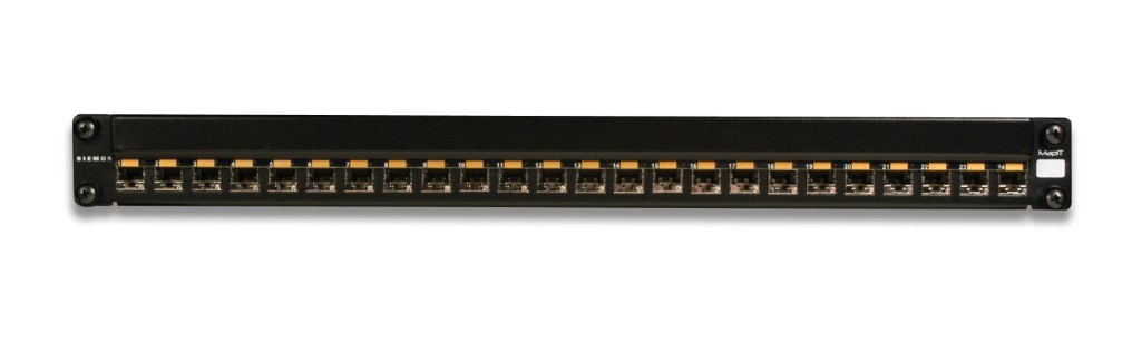
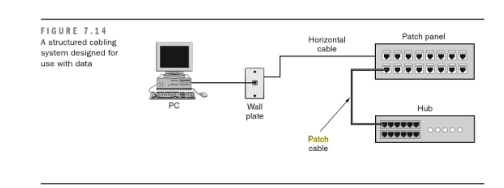
The first scenario, shown in Figure 7.14, shows the typical horizontal cabling terminated to a patch panel. The horizontal cable terminates to the 110-block on the back of the patch panel. When a workstation is connected to the network, it is connected to the network hub by means of a RJ-45 patch cable that connects the appropriate port on the patch panel to a port on the hub.

The use of a generic patch panel in Figure 7.14 allows this cabling system to be the most versatile and expandable. Further, the system can also be used for voice applications if the voice system is also terminated to patch panels.

cabling system

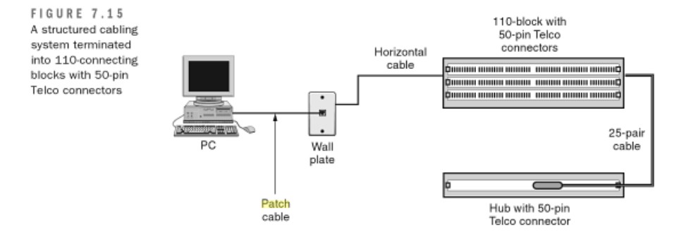
Another scenario involves the use of 110-blocks with 50-pin Telco connectors. These 50-pin Telco connectors are used to connect to phone systems or to hubs that are equipped with the appropriate 50-pin Telco interface. These are less versatile than patch panels because each connection must be termiated directly to a connection that connects to a hub.

In past years, we have worked with these types of connections, and network administrators have reported to us that these are more difficult to work with. Further, these 50-pin Telco conectors may not be interchangeable with equimpent you purchase in the further. Figure 7.5 shows the use of a 110-block connecting to network equipment using a 50-pin Telco connector.

A final scenario that is a combination of the patch-panel approach and the 110-block approach is the use of a 100-block patch cables (such as the one shown previously in Figure 7.9). This is almost identical to the patch-panel approach, except that the patch cables used in the telecommunications closet have a 110-block connector on one side and an RJ-45 on the other. This configuration is shown in Figure 7.16

17

The previous examples are fairly simple and involve only one wiring closet. Any installation that requires more than one telecommunications closet and also one equipment room will require the service of a data backboane. Figure 7.17 shows an example where data backbone cabling is required. Due to distance limitations on horizontal cable when it is handling data applications, all horizonatal cable is terminated to network equimpment (hubs) in the telecommunications closet. The hub is then linked to other hubs via the data backbone cable. Now recommend you two fiber optic patch panels, following picture shows the details.

12 Port Fiber Patch Panel Preloaded with Simplex Multimode SC Connectors

12 Port SC Duplex

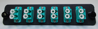
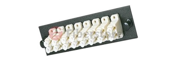
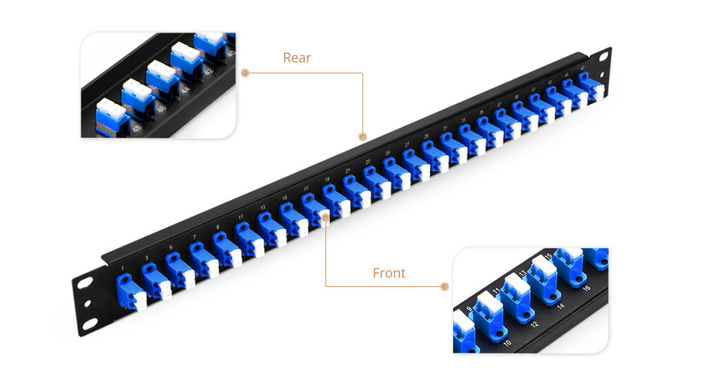
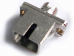
This 12 port fiber patch panel is designed to fit on a standard 19″ rack and provide optimal protection for your fiber optic applications. There are two cable entry points on the back of the fiber housing fitted with rubber grommets to protect the fiber optic cable from damage. Along with being loaded with 12 SC connections, each fiber enclosure includes one cable routing spool and one 12 fiber splice tray. Also included are zip ties, cable routing clamps, mounting screws, fiber splice sleeves and installation instructions.

24 Port Fiber Patch Panel With Multimode Duplex SC Connectors

24 port

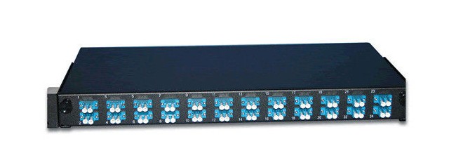
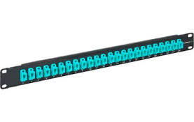
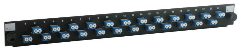
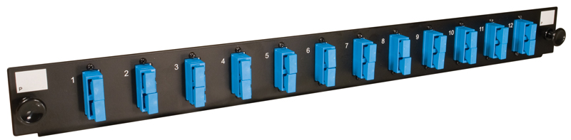
The 24 Port Fiber Patch Panel is fundamental to network system operations; whether it be testing, organization, or maintenance, we as users rely on accessible and dependable panels. Let us help you maintain your network with our Fiber Optic Patch Panels. These sliding rack mount panels feature 24 ports and come pre-loaded with 24 SC Duplex multimode adapters. If you have a few patches to make right away, make use of the included fiber management kit, which has some essential goods such as a PG 13.5 cable gland, 1 splice bridge, 8 bunny clips, 24 fiber strands, and 1 warning label for good measure. These rugged steel panels are finished with black powder coating for a clean finish, are 1U (1.75 in.) height for easy installation and access, and come with labels for easy identification during use.

Our fiber optic patch panels feature anywhere from 6 to 576 ports for the ultimate in flexibility and convenience. Plus, they’re available with LC, SC or ST connections – you’ll be able to integrate any component or piece of equipment, old and new. For modular and cabinet applications, Fiberstore carries rack mounted units that easily install in standard 19″ racks, as well as fiber patch panel wall mount units that feature built-in cable management.

Designing the Cabling System

The cable layout should be designed and a cable pulling plan developed, using the findings obtained during the site visit.The proposed cable layout should be drawn on to an existing cabling diagram of the site if it is not a new site installation. The cabling diagram that is used should include all existing cabling and cable housings. For example, all cable trays, conduits and pole lines should be illustrated. For the purpose of orientation, it is essential to incorporate outlines of buldings, roads, and fixed machinery in the diagram. The new fiber optic cable routes should then be drawn over the top of this with a dark pencil. Termination cabinets and fiber node points containg splicing trays and patch panels should also be drawn on to the diagram in pencil.

A typical building cable network layout is shown in Figure 1. In some countries, according to their loacal fire prevention codes, outdoor cables that are filled with jelly should be spliced to non-flammable indoor cables close to the cable entries. Alternatively, the fibers can be cleaned and enclosed in protective sleeving ‘zero cable’, and taken to the patch panel or optical fiber distribution frame (OFDF) directly. The cross-connection arrangements and distribution hardware needs to be specified for each cable.  In the market, there are type of fiber patch panel, for example, 12 port fiber patch panel, sc fiber patch panel, 16 port patch panel and so on. Our store offer you different types fiber optic patch panel to the customers, now we will introduce two hot sale types in our store.

black box patch panel

This Black box patch panel secures 12 breakout modules in the horizontal or zone distribution areas. It features a low profile that requires little wall space, as well as a large routing space for accessible patch cabling entrance. Top and bottom grommet holes provide easy entrance for the horizontal trunk cables. Incorporated spool rings can secure and store excess cable lengths with a safe bend radius.

24 fiber patch panel

With this High Density 24 port patch panel,  you can easily make one rack unit support your 10GB or higher applications. They allow you to quickly add new devices to your system without having to manually install or reconfigure other devices. The fiber is routed and connected on the inside of the cassette. There is no cutting, polishing, or terminating. These patch panels are perfect when you have high fiber count installations.

Figure 2 illustrates a typical cable layout diagram. Note that the diagram includes the cable fiber sizes (the number of strands in the fiber) to be installed, the locations for new and old pit boxes, the requirement for new conduit and for fiber optic termination cabinets.

If a fiber ring is being formed, the cables are normally cut in the pit, both ends are taken into the building where they are either spliced through or pig-tails are connected to the fibers before taken to a patch panel. Often, there is combination of spliced fibers (which are more secure compared to those on a patch panel) and fibers with pig-tails taken to a patch panel. Taking them to a patch panel allows the rings to be made or broken as required, but leaves them free to accidental removal. Compare the length of each cable run with the length of fiber optic cables on the reels that are to be used. Using this information, determine the location of any additional intermediate splicing locationg that are required.

Once the cable layout diagram is complete, a cable installation program should be drawn up. This document will be used by the contractor’s installation procedures and requirements. It should contain a thorough description of all the considerations and potential problems that were noted during the site survey.

The installation program should include a detailed description of the following information:

  • The logistics of pulling the cable.
  • Where the pulling equipment and cable reels should be located during the installation for each separate pull.
  • The precise location where the pit boxes, termination cabinets and splicing trays are to be located.
  • Which fibers are to be spliced and which fibers are to be taken through to a patch panel.
  • Each separate cable pull and the cable size and type to be pulled.
  • Each separate conduit installation and the size and type of conduit to be installed. Specify which conduit is to be used over each section.
  • Which cable trays are to be used.
  • The routes to be taken for cable runs through the roof space.
  • All the cable trays, conduits or other housings that will need replacing.
  • An installation schedule that would minimize traffic congestion while carrying out road works during peak hours.
  • The setting up of ‘no parking’areas where installation equipment is to be located. This should be carried out the day before the installation begins. This requirement should cover all pit boxes and manholes.
  • All observations that were made during the site visit.
  • The specific responsibilities of each member of the installation team should be defined.

When the installation is complete, document all the changes made during the installation and produce final‘as installed’drawings. This will help to ensure that the cables have been installed correctly and that future fault finding and any system upgrades will be hassle free.

Physical Cable Management

The physical level of cable management covers the actual cabling itself. Using physical cable managmement systems ensures that you keep your cables in a safe, neat layout.

Because fiber optic cabling is brittle, the glass fibers within the cables can bend only so far. If they get twisted into a knot or around a tight corner, they snap like glass. Broken fiber optic cable is hard to identify, because sometimes the light still gets through just enough to work. Think of a garden hose with a kink: Some water will gets through, but in spurts versus a steady flow of water. When a fiber optic cable sometimes lets light through and sometimes doesn’t, you end up with a flaky connection that can cause all kinds of issues out on your SAN. With orderly cable placement, if a cable does ge broken somehow, it’s easier to replace it if you don’t have to fight with that giant day-glow orange spaghetti under the floor.

A good cable management system usually comes in the form of a rack or some types of 19” rackmount panels that securely hold the cabling. The rack or panels have tracks where the cables run next to or inside your equipment racks so that they can easily yet safely flow between one component and another.

Some of these systems come with patch panels, which have rows of fiber optic ports on the front that allow you to connect the cables that come out of components or other patch panels. Patch panels give you a prelabeled system you can use to interconnect your components or other patch panels. Patch panels give you a prelabeled system you can use to interconnect your components without having to run new cabling every time you want to add or change something in your SAN layout. With patch panels, you hook up all the connections on each of your components to the ports on the panels. You run the fiber-optic cables from your server’ HBAs to a patch panel as well. All cabling is run en masse to the backs of these centrally located panels. When you want to connect components to your servers, you use short fiber optic cables (patches,) usually less than 3 meters long (abount 10 feet), to patch the ports from your arrays to the ports of your swiches to the ports for your HBAs.

Figure 1 shows how a typical patch panel solution connects your SAN components without requring you to lift a floor tile or roll a spoll of cable across the floor. Another benefit of using a patch panel is that running fiber-optic cable on a one-by-one basis can be very expensive. In a fewer times electricians have to come in to put in more cables, the better. Running a group of cables in one shot from the very beginning is much cheaper and faster than doing it one by one later.

fiber optic patch panel

Patch panel systems also make things very flexible. Now that you have all the endpoints of your SAN components in one place, you can easily control what talks to what by using the short, easy-to-manage patch cables. Following is the diiferent ports example of fiber optic patch panel, there are 12 port fiber patch panel, 16 port patch panel, 24 port patch panel.

12 port fiber patch panel loaded with a 12 port Multimode LC Adapter plate and a fiber optic splice tray. Also included is a pack of 60mm splice sleeves and a 12 pack of Multimode 62.5/125µm LC Fiber Optic Pigtails. This Pre-Loaded 1U Patch Panel comes with three adapter plates for easy expansion without the need to purchase more panels. Any unused adapter plate slots are covered with a blank plate to protect the insides of the patch panel.

12 port fiber patch panel

16 port patch panel provides efficient and easy management of fiber optic cables in the rack or cabinet. Pre-loaded, feed-thru duplex multimode connectors are mounted on a 16-gauge, cold rolled, black powder coated steel panel.

16 port patch panel

With this High Density 24 port patch panel, you can easily make one rack unit support your 10GB or higher applications. They allow you to quickly add new devices to your system without having to manually install or reconfigure other devices. The fiber is routed and connected on the inside of the cassette. There is no cutting, polishing, or terminating. These patch panels are perfect when you have high fiber count installations.

24 port fiber patch panel

Fiberstore offers a complete range of fiber optic patch panel, loaded Patch Panel Kits with pigtails from 6 ports to 36 ports in all connector types LC, LC APC, SC, SC APC, FC, FC APC, and ST and up to 72 ports with LC or LC APC. 2U Patch Panel Kits with pigtails from 6 ports to 72 ports in all connector types LC, LC APC, SC, SC APC, FC, FC APC, and ST and up to 144 ports with LC or LC APC.

Fiber Enclosure Systems and Patch Panels

As previously mentioned, fiber optic cables have a very small core that can be easily damaged if not protected properly. Also, to conform to the minimum size of a fiber optic loop and not violate the critical angle, we need to have a way to keep excess fiber optic patch cables, as well as terminated building fiber, neat and protected from damage. Fiber-optic enclosures and patch panels allow the cable installer to protect the delicate fiber cable from damage, while still making it useable for the network adminstrator. A commmon device that is used as a fiber-optic cable enclosure is called a Lightguide Interconnection Unit (LIU). The LIU provides a location to terminate individual fiber-optic strands into a patch panel, which will be discussed in the next section. An LIU is generally made of galvanized steel that is then power-coated to provide durability. Most major LIU manufactures make their devices 19 inches wide so they can be installed in a normal communications rack. If the LIU is to be located in an enviroment where there is a risk of moisture or corrosives, the LIU can be sealed with gaskets to make it virtually waterproof. Most LIUs have swing out trays in the front and the back to provide easy access to the patch panel located inside. Also, most LIUs provide a place to route excess cable to ensure that all loops are of a minimun diameter, so the cable will not get damaged and maximum ligth can traverse the cable.

Patch panels for fiber-optic cables are usually installed into the LIU. Because the core and cladding of two fiber optic cables that are to be joined together must match perfectly, the patch panel must be manufactured to exact specifications and some standard type connector must be used to ensure a good fit. (Fibe-opticon connectors are discussed in the next section.) Another patch panel issue deals with attenuation. Remember from the previous discussion that when you splice or join a fiber optic cable, you can introduce additional ligth loss or attenuation. The same holds ture for the fiber optic patch panel. The connectors on the patch panel should identify total loss at various wavelegths, and these losses should be added to any other cable loss on that particular cable to ensure compliance with standards and good operation of the fiber optic cable. Now we will introduce you two fiber optic patch panel in the market, they are 12 port fiber patch panel, 24 port patch panel from our store.

The 12 port fiber optic patch panel can be loaded with SC/LC/FC/ST adapters on the panel, front panel port are optional to fit simplex or duplex adapters, the fiber optic patch panel is loaded with inside trays and accessories.

Features
  • The shell is high intensified & insulated material, thus having excellent mechanic performance
  • It is solid and durable
  • Adapters output: 12 core
  • Strength core and shell was insulated and with grounding lead
  • Suitable for inserting installation of SC, FC, ST and LC adaptor
  • Full accessories for convenient operations

The 24 port fiber optic patch panel is reliable fiber optic organization and distribution products, it is sliding type, convenient for operations and maintenance, The 24 port patch panel has wide operation temperature and suit density fiber optic installations.

24 port Patch Panel

Specifications
  • Environment temperature: -40°C ~+80°C
  • Relative humidity: ≤85% (30°C)
  • Atmosphere pressure: 70~106KPa
  • Insulated Resistance: ≥2×10MΩ/500V (DC)
  • Intensity ≤ 15kv (DC) /1min no spark-over and no flying arc
  • Fiber bending radium guaranteed more than 40mm: ≥40mm

Application: It is applicable for straight-through connection and diverged connection in aerial layout.

  • Duct and direct buried.
  • It can protect fiber connectors commendably.

Fiber optic patch panel is an integrated unit for fiber management, we offer wall mount patch panel and rack mount patch panel, these equipment function is to fix and manage the fiber optic cables inside the box as well as provide protection. There different models to fit for 12 core fiber, 24 core fiber, 36 core fiber, 48 core fiber, 72 core fiber and 96 core fiber applications. They can be with different adapter interface including the SC, ST, FC, LC MTRJ, E2000, etc.

Optical Cables Options In SANs

Today, that high-speed network usually consists of fiber optic cable and switches that use light waves to transmit data with a connection protocol known as Fibre Channel. (A protocol is a set of rules used by the computer devices to define a common communication language.) More and more, regular Internet provider (IP)-based networks, such as the Internet, are being used as the network part of a SAN.

The act of using a network to create a shared pool of storage devices is what makes a SAN different. The network is used to move data among the various storage devices, allows sharing data between different network servers, and provides a fast connection medium for data backup and restoration and data archiving and retrieval. Devices in a SAN are usually bunched closely together in a single room, but the network allows the devices to be connected over long distances. The ability to spread everything out over long distances makes a SAN very useful to large companies with many offices.

Fiber optic cable is one of the simplest parts of a SAN and one of the most time-consuming to troubleshoot when something goes wrong. It’s better to make sure nothing goes wrong by taking care in the installation and handling of your SAN cabling.

This chapter provides reference material for readers who may be less familiar with either Fiber Channel or IP/Ethernet technology. The following we will introduce the optical cables options in SANs. Next, we will mention LC-LC cables, SC-LC cables, SMF cables.

LC-LC Cables

LC connector are used to attach fiber optic cable to SFPs and patch panels. An LC to LC fiber cable has this connector on each end. It could be used to connect two routers together, to connect a router to a 1Gbit or 2Gbit Fiber Channel device or switch, to a patch panel, or to many Gigabit Ethernet devices. These cables can be purchased in either MMF or SMF versions.

SC-LC Cables

SC connector are used to attach fiber optic cable to GBICs and patch panels. An SC to LC fiber cable has this connector on one end and an LC connector on the other end. It could be used to connect a router to an older Fiber Channel node or switch, to a patch panel, or to many Gigabit Ethernet devices. Some 2Gbit FC devices use and therefor SC connectors as well, and the router would require this cable to connect to them. These cables can be purchased in either MMF or SMF verisons.

MMF Cables

Multi-Mode Fiber is used for short distances. It is less expensive than SMF, and is the most common cables type for use inside a datacenter or campus. These cables use a larger diameter (50/125um or 62.5/125um.) fiber core on the inside of the cladding. (Cladding is the sheath around the outside of the fiber.) Most often these cables are used with SWL GBICs and SFPs. Be sure to check that the transeiver is designed to work with the cable diameter (50 or 62.5) since there are two formats. Brocade switches all work equally well with either format, so it should work as long as the transceiver is supported by Brocade and matched to the cable. Usually, MMF cables are orange, but they can ordered in non-standard colors so this is not a totally reliable way to distinguish them from SMF cables. Look for writing on the cable cladding as well.

SMF Cables

Single-Mode Fiber can be used for short distances, but due to its greater cost it is almost exclusively use for much longer distance links in combination with LWL, ELWL or WDM solutions. Generall speaking, these soloutions are desinged for SMF cables with media designed for MMF can cause problems. SMF cables use a much smaller diameter fiber core inside the cladding: 9/12um. They are usually colored yellow, but like MMF cables they can be ordered in other colors.

I hope this post was helpful to you when you are choosing optic cable in SANs. If you are interested in requesting a optical cable, please go to the Fiberstore online website.

Some Knowledge About Fiber Optic Adapters

Fiber optic adapters form a small, but critical, part of the hardware used in an optical-fiber cabling system. While the importance of adapters is often overshadowed by connectors, product manufacturers continue to stress the significant role that these devices play in overall interconnection performance.

Available for more than a decade, the fiber adapter has been a relatively stable device, with no really revolutionary breakthroughs in its technology. Rather, cable installers have seen incremental and evolutionary product enhancements, such as the introduction of a variety of metal, polymer, and ceramic materials for the adapter sleeve, and the introduction of hybrid adapters.

During all this time the fiber-optic adapter`s function has remained the same–to join and align two connectors. Adapters are available to join like connectors–SC-to-SC, ST-to-ST, or FC-to-FC–and different styles of connectors. The latter devices are called hybrid adapters and are used, for instance, to join ST and SC connectors. As we all known, hybrid adapters offer a solution for hybrid applications where the two different kinds of optical connectors or cable assemblies need to be linked with each other. The following is some types of hybrid fiber adapter.

SC to ST hybrid adapter

SC-ST adapter

SC to ST hybrid adapters are with plastic housing, flange type,zirconia sleeve for single mode and broze sleeve for multimode.Blue for single mode PC and beige for multimode PC.

FC to ST hybrid adapter

ST-FC adapter

FC to ST hybrid adapters are also flange type wit plastic housing,Blue for single mode PC and beige for multimode PC.

SC to FC hybrid adapter

SC-FC adapter

SC to FC hybrid adapter are available with plastic housing and metal housing.plastic body adapter are flange type and metal adapter are square type.

With many types of fiber-optic connectors having been developed over the last decade, cabling installers have expressed concern about the inability of adapters and connectors from different vendors to interconnect. “That`s not a problem any longer, though,” says Mike Peppler, associate director of product marketing at amp Inc. (Harrisburg, PA), because specifications for intermateability have been issued by the Electronic Industries Association and the Telecommunications Industry Association (both in Arlington, VA) and, internationally, by the International Electrotechnical Commission (Geneva). Today, most product manufacturers follow these specifications.

Fiberstore provide a complete line of adapters for fiber optic connection, like ST, SC, FC, LC, MTRJ, MPO and MU style fiber optic adapters for both multimode and single-mode fiber applications. We also can offer fiber adapter plates for ST-, SC-, MT-RJ- or LC-type connections.