Fiber Optic Modes

A fiber optic “mode” is a path that light can follow in traveling down a fiber. As the name implies, multimode cable has a larger core designed to support multiple modes, or paths, of light propagation.

When an incoherent light source such as an LED is coupled to multimode fiber, multiple paths of light from the LED are transmitted over the cable, as shown in Figure 17-1. An advantage of the larger core is easier coupling of the light source to the cable. A disadvantage is that the wider corridor for light transmission allows the multiple paths of LED lights to bounce off the sides of the fiber.

When this happens, these light paths arrive at the far end slightly out of phase, causing the light pulse to become dispersed, or spread out. This modal dispersion, or jitter, of the signal can cause problems with signal recovery at the far end. The longer the distance, the more signal dispersion there will be at a given signaling rate.

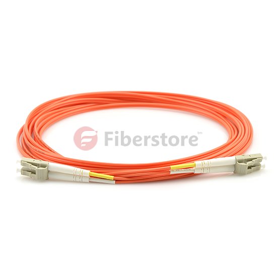
Single-mode fiber has a much smaller core, optimized to propagate a single mode, or path. When long-wavelength light (e.g., 1300 nanometers) is injected into this fiber, only one mode will be active, and the rays of light will travel down the middle of the fiber. When a coherent light source from a laser is coupled to a single-mode fiber, the single beam of laser light is transmitted over the single mode of the cable. The common single-mode fiber patch cord we use in the optical fiber system, there are singlemode LC to LC fiber patch cable, SC to SC fiber patch cable,  SC LC fiber patch cable, ST fiber patch cable.

With single-mode fiber, the signals don’t bounce against the cladding of the fiber, meaning there is no modal signal dispersion. Therefore, the light can travel a much longer distance without signal problems. The smaller core requires more precision to couple the light source to the cable, which is one reason why single-mode equipment is more expensive.

It is possible to couple a coherent laser light source to a multimode fiber. However, when this was first done for the Gigabit Ethernet media system, it was discovered that there can sometimes be a problem with signal propagation over the older cables that were common when Gigabit Ethernet was initally developed in 1999. This issue is called differential mode delay (DMD), and it is further described later in this chapter.

Since that time, newer version of multimode cables have been developed that are designed to support laser light sources. In particular, these cables support the use of a less expensive laster technology called a Vertical Cavity Surface Emitting Laser (VCSEL). These lasers are well suited for low-cost transmission at the 850nm wavelength, allowing for higher data rates over multimode fiber.

We offer a huge selection of single and multimode fiber patch cables for multiple applications: mechanical use, short in-office runs, or longer runs between and within buildings, or even underground. Gel-free options are available for less mess, and Bend Insensitive cables for minimizing bend loss, which can be difficult to locate and resolve.

Continuity Tester Polarity Verification Techniques

Polarity problems exist in both copper and fiber-optic networks. The feedback received over the years from many technicans servicing both types of networking is that fiber-optic networks experience polarity problems more often than copper networks. Polarity problems in a fiber optic network are not the result of a dirty connector, broken optical fiber, or a macrobend, they are the result of improper labeling and or human error.

A continutiy tester is the best tool to assist in polarity verfication because it emits visible eye-safe light. Depending on the complexity of the network, verifying the polarity of a channel may be time consuming. It is a good idea to bring a note book and record your observations as you work your way from one end of the chanel to the other.

ANSI/TIA-568-C defines two polarity schemes for duplex Fiber Optic Patch Cable: A-to-A and A-to-B. The most commonly deployed scheme is A-to-B, therefore this section focuses on that scheme. Because there are many different network configurations, we will only describe polarity verfication techniques for the configuration shown in Figure 17.28.

Each end of a duplex patch cord should identify position A and position B. This is typically accomplished with raised lettering on the latch that holds together the two connectors at each end of the patch cord. A raised letter latch holding together two SC connectors is shown in Figure 17.29. Because of the physical size on an SC connector, the raised lettering is easy to read. However, this is not the case with small form factor connectors such as the latched LC pair shown in Figure 17.30.

The first step in verifying the polarity the channels shown in Figure 17.28 is to de-energize the equipment at both ends of the network. Since latched duplex patch cords are used, unplug both connectors from both ends of the patch cords at each end of the network. Using the continuity tester, verify that connectors on each end of a patch cord are oriented so position A goes to position B. You can do so by inserting the ferrule of the A position connector into the continuity tester as shown in Figure 17.31.

With the connector inserted, energize the continuity tester and check to see if light is exiting the optical fiber in position B at the opposite end of the patch cord. If light is exiting the optical fiber in position B, the polarity is correct. If light is exiting the optical fiber in position A, the polarity is not correct. With the continuity tester still attached and energized, unlatch both connectors, swap locations, and relatch. Verify light is exiting from the optical fiber in position B. Repeat this test for the other patch cord and correct as necessary.

With both patch cords properly configured, the next step is verify the polarity of the horizontal cabling. To minimize access to other horizontal cabling, you should work from the equipment outlet to the patch panel. Remove the cover of the equipment outlet and plug both connectors at one end of the patch cord into the receptacles on the equipment outlet. Do not disturb the horizontal cabling connections.

Insert the ferrule of the A position connector at the end of the patch cord into the continuity tester as shown earlier in Figure 17.31. With the connector inserted, energize the continuity tester and check to see if light is exiting the horizontal cabling optical fiber in position B at the patch panel. If ligth is exiting the optical fiber in position B, the polarity is correct. If light is exiting the optical fiber in position A, the polarity is not correct. With the continuity tester still attached and energized, unlatch both horizontal cabling connectors at the back of the equipment outlet, swap locations, and relatch. Light should be exiting from the optical fiber in positon B. Reinstall the equipment outlet cover.

Fiberstore Solutions ensures its range of fiber patch cords are manufactured to the industry’s highest standards for network cabling using the highest quality optical fiber, sheathing and connectors available. All of our ST to ST, SC to SC and LC to LC multi-mode fiber patch cables deliver high-capacity, high-data-rate transfer and are optimized for dense wavelength division multiplexing (DWDM) and optical networking technology. Now LC fiber optic cable is in huge stock, buy now same day shipping to your country.

Auxiliary Video Inputs Resolution and Refresh Rate

At the time of writing, the PC video input (VGA-DVI) and the document camera (DVI-HDMI) on the Cisco TelePresence codec operate at 1024×768 resolution with a refresh rate of 60Hz. The PC must be configured to output this resolution and refresh rate on its VGA output interface. Likewise, the document camera must be configured to output this resolution and refresh rate on its DVI output interface. The majority of PCs on the market at the time the product was designed use 1024×768 resolution and VGA interfaces, although an increasing number of models are beginning to support higher resolutions and are beginning to offer DVI and even HDMI interfaces instead of, or in addition to, VGA. Future versions of the Cisco TelePresence codec might support additional resolutions, refresh rates, and interface types for these connections.

VGA is an analog interface. DVI comes in three flavors: DVI-A that is analog, DVI-D that is digital, and DVI-I that can dynamically sense whether the connected device is using analog (DVI-A) or digital (DVI-D). It is worth mentioning that the first generation Cisco TelePresence codec offers a DVI-A connector for the PC connection. The other and of the cable that attaches to the PC is VGA. So the signal from the PC is a VGA analog to DVI-A analog connection. Now we will introduce you the VGA and DVI fiber video converter from our fiberstore.

Fiberstore’s VGA Video Multiplexer,a flexible professional solution for long distance transmission of high resolution VGA or RGB Component Video signals through single fiber solutions, and single-mode or multi-mode fiber cables which allow for the transmission of accompanying stereo audio, RS232 data, Loopback output and support USB Keyboard/Mouse. applications include specialized Media Display, Security Systems, Universities, Industrial Monitoring, Airport / Airplane / Metro / Railway and large-scale conference sites including stadiums, where long distance transmission of computer video signals are necessary, fiber optic transmission ensures high quality signals with no interference.

VGA Video Converter

Fiberstore’s DVI Fiber Video Converter are the perfect choice for both large and small Pro AV installations. Featuring DVI video resolutions up to WUXGA 1920×1200 and HDTV video resolutions up to 1080p. Fiberstore’s DVI Fiber Optic Converter, a flexible professional solution for long distance transmission of high resolution video signals through single fiber solutions, and single-mode or multi-mode fiber cables which allow for the transmission of accompanying stereo audio, RS232 data, Loopback output and support USB Keyboard/Mouse. applications include specialized Media Display, Security Systems, Universities, Industrial Monitoring, Airport / Airplane / Metro / Railway and large-scale conference sites including stadiums, where long distance transmission of computer video signals are necessary, fiber optic transmission ensures high quality signals with no interference.

HDMI

Fiberstore supply SDI Digital over fiber video converterr, 3G-SDI Digital over fiber video converter, HD-SDI over fiber video converter, and SDI-HDMI over fiber video converter. All of our optical/electric interfaces are in accordance with international standards, free of adjustment prior to mounting and applicable in various operating environments. Please feel free to contact us for all your Digital SDI&HDMI&VGI and other video conversion requirements.

Common Types Of Fiber Optic Patch Cord

A patch cord (sometimes called a patch cable) is a length of cable with connectors on the ends that is used to connect an end device to something else, such as a power source. One of the most common uses is connecting a laptop, desktop or other end device to a wall outlet.

Generally, fiber optic patch cable consists of two parts: the fiber optic cable and the fiber optic connectors. fiber optic patch cables are named by the cables and the connectors together, for example, a LC to SC 3 meters single mode simplex APC types Fiber Optic Patch Cord, here the name LC and SC stand for the name of specified fiber optic connector, 3 meters is the whole cable length, single mode refer to the cable type, simplex means this cable is with one single core, APC is the polish type of the fiber optic connectors. fiber optic patch cables are important components used in the fiber optic communications network.

Fiber optic patch cables may be split into different types according to fiber cable mode, cable structure, connector types, connector polishing types and cable sizes. However nowadays we would like to introduce the normal kinds of fiber patch cable based on fiber connectors.

Most Common Forms of Fiber Patch Cables include:

SC Fiber Optic Patch Cord

SC fiber optic patch cable is one of the earliest type and something of the very most commonly used fiber optic cable, it is simple to use and value saving, SC fiber cable is widely used in fiber optic networks. SC fiber patch cable is by using zirconia sleeve and plastic housing. Oahu is the standard fiber optic cable assemblies, with simplex, duplex patch cords and standard pigtails. Fiberstore offer you different types of SC fiber patch cord, such as SC to SC fiber cable, single mode fiber SC to LC, ect.

The SC fiber optic patch cord was invented by the Japanese company NTT. It really is probably the most popular fiber optic patch cords. SC fiber optic patch cord features low priced, simplicity along with good durability, SC fiber optic patch cords is with a locking tab about the cable termination; it’s a push and pull type fiber optic connector.

ST Fiber Optic Patch Cord

ST fiber cable connector features bayonet-style housing along with a long spring-loaded ferrule support the fiber. They are available in multi-mode or single mode versions. Horizontally mounted simplex and duplex adapters are available with plastic or metal housing. It is the standard fiber optic cable assemblies, with simplex, duplex patch cords and standard pigtails.

ST fiber optic patch cords standard was created by AT&T. this sort of cable is with straight tip type terminations. There is only simplex ST fiber optic patch cord with no duplex ones. These days ST fiber optic connectors are generally having a metal housing ,nevertheless, there are plastic housing ST fiber connectors, more and more people often use metal housing ST. ST APC fiber optic patch cord are also available.

LC Fiber Optic Patch Cord

The LC fiber optic cable is by using a small form factor connector and is perfect for high density applications.LC fiber optic patch cord connector includes a zirconia ceramic ferrule measuring 1.25mm O.D. having a PC or APC endface, and provides optimum insertion and return loss. It is the standard fiber optic cable assemblies, with simplex, duplex patch cords and standard pigtails.

LC will be the short kind of Lucent Connector. LC fiber patch cord connector can be a push and latch structure, with plastic housing and accurate 1.25mm ceramic ferrule. LC type is a well-liked type of small form fiber optic patch cord which decreases the space and it’s also popular for densely installation.

FC Fiber Optic Patch Cord

FC fiber optic patch cords are with FC fiber optic connectors, the industry screw type connection. FC fiber optic patch cords were quite definitely popular previously, but people have a tendency to use LC and SC to switch FC more and more. It’s the standard fiber optic cable assemblies, with simplex, duplex patch cords and standard pigtails.

The FC fiber optic patch cable comes in both single mode and multimode versions, and it is fully intermateable with NTT-FC products. Both SMF and MMF versions FC fiber optic patch cord have a zirconia ceramic ferrule with pre-polished PC profile and convex spherical end.

MTRJ Fiber Optic Patch Cord

MTRJ fiber optic patch cables feature the plastic ferrule and duplex design. MTRJ fiber optic patch cables are female connector type and male connector types, the MTRJ is a born duplex connector that utilize precision molded MT ferrules pioneered by NTT, together with precision metal guide pins and precise housing dimensions to ensure fiber alignment when mating. MT-RJ fiber optic patch cords is reliable and simple to terminate.

To facilitate installation of our active fiber equipment we support a large selection of fiber optic patch cords. The always in stock fiber cables include optical connectors such as: SC, ST, LC and FC type, simplex and duplex. Our patch cords range from 0.5m to 10m and have almost all available combination of optical connectors. The most available lengths are 1m, 2m, 3m, 5m, and 10m patch cords. All single-mode patch cords are UPC polished (Ultra Physical Contact), while the multi-mode cables are PC polished. All patch cords are manually tested and verified and each patch cable is individually sealed and labeled with measured optical performance.

Fiber Patch Cord Reliability

Fiber optic patch cords are one of the simplest elements in any optical network, consisting of a piece of fiber optic cable with a connector on each end. Despite its simplicity, the patch cord can have a strong effect on the overall performance of the network. The majority of problems in any network occur at the physical layer and many are related to the Fiber Optic Patch Cord quality, reliability, and performance. Therefore, using patch cords that are more reliable helps reduce the chance of costly network downtime.

Network designers would prefer components with a history of proven long-term performance. However, since optical networking is a relatively new technology, there is no significant long-term data for many components. Therefore, designers must rely upon testing from the component manufacturer or supplier that can simulate this history and assure the quality and reliability over the life of the network. This paper discusses the importance of quality, reliability, and performance as they relate to industry standards and manufacturing practices. The performance of the patch cord is also studied using a “perfect patch cord” and polishing observations as tools to understand patch cord principles.

Patch cord reliability is guaranteed not only by using quality components and manufacturing processes and equipment, but also by adherence to a successful Quality Assurance program 4). While patch cords themselves are typically tested 100% for insertion loss and return loss, if applicable, there are many other factors that need to be monitored to insure the quality of the patch cord.

One of the most important factors is the epoxy. Epoxies typically have a limited shelf life and working life, or “pot life.” This information is readily available from the manufacturer. It is absolutely necessary that both of these criteria be verified and maintained during manufacture. Epoxy beyond its expiration date needs to be discarded. Chemical changes affecting the cured properties of the epoxy can occur after this date. This date can also be dependent on storage conditions, which need to be observed.

Most epoxies used in fiber optic terminations are two-part epoxies and, while they cure at elevated temperatures, preliminary cross-linking will begin upon mixing. Once this has started, the viscosity of the epoxy can begin to change, making application more difficult over time. The epoxy can become too thick to fill the ferrule properly and too viscous to enable a fiber to penetrate, causing fiber breakage.

Mixing two-part epoxies introduces trapped air, or “bubbles”, which is injected into the connector. This trapped air introduces inconsistency in the cured epoxy, leading to a high risk of mechanical failure. The trapped air, or bubble count, must be minimized.

Many of the tooling used in patch cord assembly also has periodic maintenance and a limited tool life. This includes all stripping, cleaving and crimping tools. Most stripping tools, whether they are hand tools or automated machines, can be damaged by the components of the cable, most notably the aramid yarn strength members. Buffer strippers will dull with prolonged usage, increasing the likelihood that they will not cleanly cut the buffer. This can lead to overstressing the fiber when the buffer is pulled off. When a cleaving tool wears out and a clean score is not made, it is almost impossible to detect during manufacturing. However, the result could be non uniform fiber breakage during the cleave, which can result in either breaking or cracking the fiber below the ferrule endface. In this instance, the connector will have to be scrapped. Even crimp tools require periodic maintenance to insure the proper forces and dimensions are consistent. Crimp dies also have a tendency to accrue epoxy build-up, which can affect the crimping dimensions and potentially damage the connector.

The integrity of the incoming materials and manufacturing processes, once specified, needs to be adhered to all the appropriate guidelines and procedures. The importance of these materials not only has a strong influence on product reliability, but also on product performance.

Fiberstore manufactures and stocks fiber optic patch cables. Our stock cables feature FC/PC, FC/APC, and SMA connectors, and use single mode (SM),or multimode (MM) fiber.For example, LC to LC fiber patch cable, multimode fiber patch cables, single mode fiber SC to LC. We offer ar-coated cables for fiber-to-free space use, lightweight cables for optogenetics, high-power cables, and many other specialty fiber patch cables from stock. We also offer multimode fiber bundles, as well as custom patch cables with 24 hour turnaround on many orders. If you do not see a stock cable that is suitable for your application, please contact us. Our extensive experience with fiber patch cables enables us to offer a custom patch cable service that can ship on the same day, without a minimum order quantity.

Network Fiber Connectors

An optical fiber connector terminates the end of an optical fiber. A variety of optical fiber connectors are available. The main differences among the types of connectors are dimensions and methods of mechanical coupling. Generally, organizations standardize on one kind of connector, depending on the equipment that they commonly use, or they standardize per type of fiber (one for MMF, one for SMF). Taking into account all the generations of connectors, about 70 connector types are in use today.

As shown Figure 4-12, the most popular network fiber-optic connectors inclued

● Straight-tip (ST): An older bayonet style connector widely used with multimode fiber, as well as single-mode.
● Subscriber connector (SC): Sometimes referred to as square connector or standard connector. It is a widely adopted LAN and WAN connector that uses a push-pull mechanism to ensure positve insertion. This connector type is used with multimode and single-mode fiber.
● Lucent connector (LC): Sometimes called a little or local connector, it is quickly growing in popularity because of its smaller size. It is used with single-mode fiber and also supports multimode fiber.

Because light typically only travels in one direction over optical fiber, two fibers are usually required to support full-duplex operation. Therefore, fiber-optic patch cables bundle together two optical fiber cables and terminate them with a pair of standard single fiber connectors. Some fiber connectors accept both the transmitting and receiving fibers in a single connector known as a duplex connector, also shown in Figure 4-12.

Fiber Optic Patch Cables are required for interconnecting infrastructure devices. Some of the common patch cords are

● SC-SC multimode patch cord
● LC-LC single-mode patch cord
● ST-LC multimode patch cord
● SC-ST single-mode patch cord

LC LC fiber optic cable from Fiberstore

LC LC fiber optic cable

● LC-LC Connectors
● Multimode Duplex fiber optic cable
● Micron: 62.5/125um
● Complete with Lucent Technologies aqua jacket
● Bandwidth transmitting rates up to 10 gigabits
● All of our fiber optic patch cables feature the high degree connectors
● Fiber class: OM1
● Color: Orange

Fiber cables should be protected with a small plastic cap when not in use.

The color of the fiber jacket is often used to distinguish between single-mode and multimode patch cords. This is because of the TIA-598 standard, which recommends the use of yellow jacket for single-mdoe fiber cables and orange (or aqua) for multimode fiber cables.

Fiberstore provide various types of fiber patch cords including single mode, multimode, multi core, and armored versions. You can aslo find fiber optic pigtails and other special patch cables here. For most of them, the SC, ST, FC, LC, MU, MTRJ, E2000, APC/UPC connectors are all available, even we supply MPO/MTP fiber cables.

Some knowledge about Fiber Optic Patch Cords

Introduction

In the context of optogenetics experiments with the rotary joint, a fiber optic patch cord is needed to connect the light source and the rotary joint and yet another patch cord to connect the rotary joint and the fiber-optic cannula.

Structure of a patch cord

The core and the cladding are two layers that make up the lightguide. However, the light travels inside the core of the fiber-optic, barely or not inside the cladding. For this reason, interconnected fiber-optics should have the same core diameter. Different cladding diameters have no influence on the coupling efficiency.

The buffer is a protective layer that tightly encircles the cladding. For patch cords, we usually recommend the use of another protective layer, called jacket, which is a loose tube covering the previously mentioned layers of the cable.

For a better fiber protection, we also offer larger jackets made of PVC tubing. In this case, we use the following color convention, or we can use the black jacket if preferred. Metal jackets or jackets made of other materials are also available on request.

Mono fiber-optic patch cords

The simplest form of the patch cord is a piece of fiber with buffer coating and two ferrules on its ends. So far, the msot popular fiber in optogenetics research is a fiber with a 200 um core diameter and NA=0.22.

Note 1: The fiber diameter and its numerical aperture (collection angle) limit the coupling efficiency into the fiber. Therefore, for higher coupling from sources like LEDs into an optical fiber of a specific diameter, please select a higher NA fiber an follow it all the way through to the fiber optics cannula.

Note 2: The zirconia ferrules are prefferred for being less expensive, of tighter tolerance, harder, mass produced etc. However, due to the fluorescence of the zirconia ferrules they are not recommended for applications involving fluorescence measurements.

Dual fiber-optic patch cords

A dual fiber optic patch cord has two fiber-optic strands within the jacket, where the fiber ends are inserted into the mono or dual fiber ferrules or connectors.

Some dual fiber patch cords were especially designed to easily bring the light from the two optical channels of the 1×2 rotary joint into a dual fiber cannula.

There are several types of dual fiber patch cords, depending on the type of connectors and cannulas used.

Branching fiber-optic patch cords

A branching fiber patch cord consists of multiple single fiber patch cords that are at one end joined within one connector and its ferrule, while the loose side of the patch cords ends with mono fiber ferrules or connectors.

We offer fiber-optic patch cords that branch from one input to N output connectors. These patch cords have a single FC or SMA connector on bundled fibers end, and an FC,SMA, M3, zirconia or metal ferrule for each fiber on the other end. If the source is an LED or a lamp, the optical power entering the fiber bundle is divided between the channels. In the case of a laser, please refer to the Mini Cube section. Now following we recommend you some type patch cords from our store, there are LC to LC fiber patch cable, SC to SC Fiber Optic Patch Cable.

LC-LC fiber optic patch cables are used to send high-speed data transmissions throughout your network. LC/LC fiber optic cables connect two components with fiber optic connectors. A light signal is transmitted so there is no outside electrical interference.

SC-SC fiber patch cords are primarily used in high bandwidth networks where you must send large amounts of data at high speeds. Use a SC to SC fiber jumper cable to connect two devices with SC connections. Since the data is sent via a light signal, there is no electrical interference. All of our SC fiber cables have been factory tested to ensure proper performance.

Our Fiber Optic catalogue is designed to provide you with everything you need to set up your fiber optic network, from cables to connectors to patch panels and termination boxes. Our fiber optic cables are available with combinations of LC, SC, ST, FC, and MTRJ connectors and come in 1, 2, 3, 5, and 10 meter lengths (and OM3 cables up to 30 meters). And if these parameters do not meet your fiber needs, take a look at our fiber cable Custom Calculator and create yourself a custom cable. If you have even further specific needs beyond our calculators, please call our resident fiber specialist for a fast and personalized quote on any cable or fiber accessory you require.