How to Test the Sensitivity of a Fiber Optic Receiver by using an Optical Attenuator

Knowing how to test the sensitivity of a fiber optic receiver is an important skill. A fiber optic receiver provides optimal performance when the optical input power is within a certain range. But how do you test the receiver to see if it will provide optimal performance at the lowest optical input powers? One way is to use Optical Attenuators, such as bulkhead attenuators. Typically only a couple of values are required to complete your testing. This process involves three steps shown as following.

  1. Measure the optical output power of the fiber optic transmitter with the power meter. Remember that industry standards define transmitter optical output power and receiver optical input power for a particular network standard. If you are testing a 100BASE-FX receiver, you should be using a 100BASE-FX transmitter. The optical output power of the transmitter should be within the range defined by the manufacturer’s data sheet.
  2. Connect the transmitter to the receiver and verify proper operation at the maximum optical output power that the transmitter can provide. You need to test the receiver at the minimum optical input power that the receiver can accept while still providing optimal performance. To do this, you need to obtain the lowest optical input power level value from the manufacturer’s data sheet.
  3. Calculate the attenuation level required for the test. For example: The transmitter’s optical output power is -17 dBm and the minimum optical power level for the receiver is -33 dBm. The difference between them is 16 dB. You would use a 16 dB bulkhead attenuator at the input of the receiver and retest the receiver. If the receiver still operates properly, it’s within specifications.

Note: The optical loss is not considered about in the example above. Suppose that the transmitter is located 10 km from the receiver and the loss for the whole optical fiber link (including interconnections) is 6 dB, then you should use a 10 dB bulkhead attenuator rather than the 16 dB one for your test.

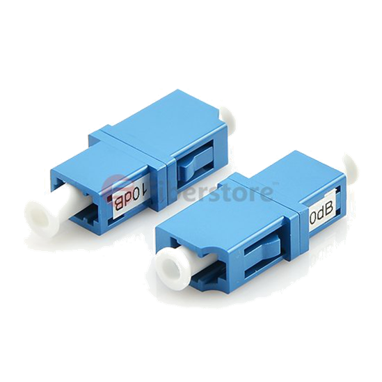
10dB Bulkhead Attenuator

This article source is from fiberopticshare blog.


Fiber Optic Access Network Will Be The Main Force Of Internet Information Highway In The Future

As with the rapid development of social information, fiber optic technology and devices which are dedicated to provide transfer of a new business for WAN and fiber optic access network. Developments of MSTP and PON are the most representative. They are also the best solution to provide various new business in the MAN and fiber optic access network which are based on fiber optic transmission technology. As water to the fish, the developments of fiber optic access technology can not without the support and development of fiber optic access devices.

Due to the constantly updated fiber optic access technology and more and more manufacturers’ accession, nowadays the fiber optic access devices categories are more and more obvious, mainly divided into three categories:

  • Fiber optic connection elements, it is applied into telecommunications and computer network terminal connections, related product: Fiber optic patch cable, fiber optic connector and so on.
  • Fiber optic transceiver, it is utilized for computer network data transmission, related products: Fiber optic splitter, fiber patch panels and so on.
  • Fiber optic engineer devices and fiber optic testers, it is specially for large-scale project, related products: Fiber optic fusion splicer, fiber optic testers.

Next we will introduce these three fiber optic access devices with a representative products respectively, they are fiber patch cables, fiber optic splitter, fiber optic fusion splicer.

Fiber optic patch cable (shown as the figure)is fiber optic cable or fiber optical unit which without fiber optic connector, it is used in fiber distribution frames on various link roads. Fiber patch cables are also used in long distance local optical network, data transmission and private network, various testing and control system.

Fiber optic splitter (shown as the figure), someone calls it as fiber coupler, it belongs to optical passive components, it is used in the telecommunications networks, fiber cable television networks, subscriber loop system. Fiber optic splitters can be divided into standard coupler (double branch, unit 1 x 2, that is, the light signal into two power, for example, 1×2 fiber optic splitter, 1 x4 fiber optic splitter, 1 x 8 fiber optic splitter and so on), star/tree fiber splitters and wavelength division multiplexer (WDM, if the wavelength is a high-density separation and wavelength spacing is narrow, it belongs DWDM).

Fiber optic fusion splicer(shown as the figure) is mainly used in telecommunication for fiber optic cables construction and maintenance, it is applied into telecommunication operators, engineering companies, private network, also used in the production of optical passive and active devices and fiber optical modules for fiber splicing.

All above the fiber optic access devices highly improve the data transmission and processing capabilities of fiber optic access network, and at the same time they can bring two advantages:

First, it solved the long distance transmission problems of fiber line attachment,and made its coverage range more widely. In this way, then it can reduce the number of transit nodes through whole the coverage network, make the structure of the network easier.

Second, it satisfied people’s needs to various broadband business, and improve the quality of new business data. It solved the problem of traditional copper cable access network fundamentally and laid a good foundation for achieving the dream of FTTH. I believe that in the future, fiber optic access network will be the main force of internet information highway.

Planar Lightwave Circuit (PLC) Based Optic Power Splitter

In a power-splitting PON, an optical power splitter is the passive device in the outside plant that physically connects to the CO with a feeder fiber. It also connects to a number of ONUs via a series of distribution fibers. In the past few years, significant improvements in reliability, cost per port, insertion loss, and splitting-ratio nonuniformity, have been demonstrated with planar lightwave circuit (PLC)-based splitters. Central to the splitter is a PLC chip comprising of optical waveguides fabricated on a planar substrate, typically made of silicon or quartz, to form a cascade of Y-branches. For a 1 × splitter, one side of the PLC chip is aligned to a fiber whereas the opposite side is aligned to an array of PON is typically N = 16 and N = 325, but with an increasing demand of up to N = 64, thereby making the alignment of the fiber array to the PLC chip more challenging. Compared to fused biconical-taper-based splitters, PLC technology allows for chip-size devices with the potential of integrating multiple functions, e.g. WDM coupler, onto a single clip. It also enables a more uniform loss over a wide operating range of wavelengths from 1250 nm to 1625 nm, and operaton of a wide range of temeratures from -40℃ to + 80℃. Figure 3.2 illustrates the measured insertion losses from samples of 1×32 optical splitter approved by AT&T Labs for use in the Project Lightspeed FTTH trial, showing uniform loss over a wide wavelength range.

Aside from uniform loss, the insertion loss of PLC splitters is another important parameter in network implementations that will influence system performance and the overall coast per drop. Lower insertion loss PLC slitters will extend the reach and number of customers that can be accommodated within the same PON, yielding higher revenue per PON for service providers. Aside of the theoretical splitting loss attributed to the division of optical power at the input port equally into N output ports, and given by the fromula:

Theoretical splitting loss (dB) = 10 × log10(1/N)

A PLC splitter suffers from excess insertion loss from fiber array alignment to the PLC chip, fiber array uniformity caused by pitch and depth inaccuracies in the v-grooves of fiber array block that holds the fiber array, splitting ratio uniformity caused by imperfections in the PLC chip due to manufacturing, inherent chip material loss, and inherent chip material loss, and connector loss. The targeted areas for improvement of insertion loss in PLC splitters have been in reducing connector losses, and improving fiber array and splitting ration-nonuniformity. The connector loss can be improved from 0.5 dB trough using high quality ferrules and an excellent polishing method. With advances in manufacturing process of the fiber array block and PLC chip, insertion losses from fiber array nonuniformity and splitting-ratio nouniformity can be reduced from 0.7 dB to 0.4 dB and 1.8 dB to 1.0 dB, respectively. Collectively, the excess insertion losses of PLC splitters are currently 1 – 1.5 dB above the ideal theoretical splitting loss with a nonuniformity within 2 dB over the specified range of operating wavelengths from 1250 nm to 1625 nm.

Fiber optical splitter is used to split the fiber optic light into several parts at a certain ratio . The fiber optic splitter is an important passive component used in PON FTTX networks. There are mainly two kinds of passive FTTH optical splitters: one is the traditional fused type splitter as known as FBT coupler or FBT WDM optical splitter, which features competitive price; the other is the PLC splitter based on the PLC (Planar Lightwave Circuit) technology, which has a compact size and suits for density applications. The common PLC Splitters configurations are 1×4, 1×8, 1×16, 1×32, 1×64 and 1×128, but 2×4, 2×8, 2×16, 2×32 configurations are also available.  Fiberstore singlemode& multimode FBT optical splitter comes in a wide range of split ratios with single/double/three windows. The main packages include box type and stainless tube type. The former is usually used with 2mm or 3mm outer diameter cable, while the latter is usually used with 0.9mm outer diameter cable. Our optical splitter can be terminated with your choice of connectors or installed in rack mount modules. Please contact us for the special customized needs.

New Application of Fiber Optic Connector Assembly at the Scene

Recent years, PON technology has been more widely used in the fiber optic industry because of its advantages on building cost, protection cost and the broad width. And in China, the three major telecom operators – China telecom, China unicom and China mobile all bring the EPON and GPON into the telecommunication network, at the same time, in order to support the application of PON technology, ODN network is built strongly, then it put forward higher requirements to fiber optic connection, protection as well as the application and management of fiber cable devices, the most obvious device among them is fiber optic patch cable.

We all know that tradition fiber patch cables are made to follow as the certain length of fiber optic connector assembly process, different lengths of fiber cables and connectors composed of a wide variety of fiber patch cords, they can be used in fiber optic patch panels, fiber transfer boxes, fiber cable devices and the connection between the devices and other optical ports, but just because these different fiber patch cables, it bring heavy pressure to storage management. Except this, traditional factory custom the length of fiber patch cables usually more than the actual length if the route and it leaves the length of the excess in a small disk space, we can see from the figure that not only it adds the cost of distribution frame and other cable devices but also not easy to manage, and too longer fiber cables always happens intertwined, knotted squeeze and circumstances, then result in unnecessary trouble, increase the cost of maintenance and management.

longer cable

Therefore, how to control the length of fiber patch cables effectively, to avoid all the trouble. To solve the problem, Fiberstore makes his opinion. we use the on site assembly of fiber connectors, and on the 2 mm or 3 mm fiber pigtail?into end and make fiber patch cable at the scene, replacing the traditional custom factory fiber patch cables, it can greatly alleviate the traditional fiber patch cables left too long, difficulties of managements, frequent failure those a series of maintenance problems. Fiberstore comes with the close communication with all the operators and joint efforts, apply the fiber optic connector assembly of FTTH at the secne into fiber patch cables managements of fiber equipments.

After the constant experiments and used for many time successfully, we have to believe that the embedded optical fiber types of fiber optical connector assembly at the scene will be the first choice for the fiber distribution frame, cable box, optical distribution boxes and other cable device in the future, it also can give ODN network cabling system maintenance and management to bring a revolutionary change.

A Comparison between Tee Coupler and Star Coupler

In many applications, it may not be possible to have a design of many point-to-point connections. In these cases, optical couplers are used. A fiber optic coupler is a device that combines or splits optical signals. A coupling device may combine two or more optical signals into a single output, or the coupler may be used to take a single optical input and distribute it to two or more separate outputs. The Figure below shows an example of a basic four-port coupler, generally named fiber coupler 1 × 4.

4-Port Coupler

Many couplers are designed bidirectionally, which enables the same coupler to be used to combine signals or split signals. An optical coupler being used to split a signal may be referred to as an optical splitter. Couplers are available with a wide range of input and output ports. A basic coupler may have only one input port and two output ports. Today’s technology supports couplers with up to 64 input and 64 output ports, as shown below.

128-Port Coupler

There are many different types of couplers, and the number of input and output ports is dependent on the intended usage. Some of the types of optical couplers are optical combiners, Y couplers, star couplers, tee couplers, and optical splitters. In this article, we will only focus on the tee coupler and the star coupler and give you a comparison between them.


Tee Coupler

A tee coupler is a three-port optical coupling device that has one input port and two output ports, as shown below.

Tee Coupler

The tee coupler is a passive device that splits the optical power from the input port into two output ports. The tee coupler is in essence an optical splitter. The uniqueness of the tee coupler is that this type of coupler typically distributes most of the optical input power to one output and only a small amount of power to the secondary output. Note that when the outputs are evenly distributed, the coupler is called a Y coupler. The tee coupler is also referred to as an optical tap, due to the nature of the device. A majority of the power continues forward, but a portion of the signal (determined by the splitting ratio) is tapped to be used for an output port.

The tee coupler is a 1 × 2 coupler or 1 × 2 fiber splitter, meaning that it has one input port (or connection) and two output ports. As previously stated, the optical output power of the two output ports is typically not evenly distributed. Common splitting ratios are 90:10, 80:20, 70:30, 60:40, and 50:50 (a Y coupler). Not all manufacturers follow the convention of placing the larger value to the left of the colon and the smaller to the right. Some manufacturers simply reverse this and place the smaller value to the left of the colon and the larger to the right.

A typical use for a tee coupler would be to supply optical signals to a bus type network of in-line terminals. Assuming ideal conditions and a 90:10 split on the tee coupler, the first terminal would receive 10 percent of the optical signal and 90 percent of the optical signal would go forward to the next tee coupler.


Star Coupler

The star coupler is used in applications that require multiple ports (input and/or output). The star coupler will distribute optical power equally from one or more input ports to two or more output ports. Here is a basic star coupler with four input ports and four output ports. Star couplers are available in 1 × 64 up to 64 × 64 dimensions.

8-Port Star Coupler

A special version of the star coupler, called a tree coupler, is used when there is one input port and multiple output ports or when there are multiple input ports and one output port.

Star couplers are frequently used in network applications when there are a large number of output terminals. In our tee coupler example, we had to account for interconnection insertion loss and coupler insertion loss at each tee connection. However, with the star coupler there is only one coupler insertion loss regardless of the number of ports. With only one coupler insertion loss, a multiple port star coupler is more efficient than a series of tee couplers. So the larger the network is, the more efficient the star coupler becomes.

Two types of star couplers are commonly used: the reflective star and the transmissive star. Couplers are typically considered to be a black box, that is, only the manufacturer knows what’s inside. However, many star couplers are made of fused optical fibers as a type of fused fiber coupler.


Advantages of Star Coupler compared to Tee Coupler

The key advantage to the star coupler is that there is only one insertion loss caused by the coupler. The only remaining insertion losses are from the interconnections. The advantage of the star coupler becomes very apparent as the number of ports increases. Here is a simple loss-comparison chart that reveals the significance in the number of terminals versus loss for the tee and star couplers.

Real Tee Coupler VS. Real Star Coupler Comparison Chart

A star coupler has another advantage over a series of tee couplers. If one of the tee couplers in the series is disconnected, none of the other terminals down the line will receive an optical signal. However, disconnecting a terminal from the star coupler will not impact the operation of the other terminals.

Related Article: Overview of Bi-Directional Transceiver Modules

Testing Fiber Optic Splitters Or Other Passive Devices

A fiber optic splitter is a device that splits the fiber optic light into several parts by a certain ratio. For example, when a beam of fiber optic light transmitted from a 1X4 equal ratio splitter, it will be divided into 4-fiber optic light by equal ratio that is each beam is 1/4 or 25% of the original source one. A Optical Splitter is different from WDM. WDM can divide the different wavelength fiber optic light into different channels. fiber optic splitter divide the light power and send it to different channels.

Most Splitters available in 900µm loose tube and 250µm bare fiber. 1×2 and 2×2 couplers come standard with a protective metal sleeve to cover the split. Higher output counts are built with a box to protect the splitting components.

Testing a coupler or splitter (both names are used for the same device) or other passive fiber optic devices like switches is little different from testing a patchcord or cable plant using the two industry standard tests, OFSTP-14 for double-ended loss (connectors on both ends) or FOTP-171 for single-ended testing.

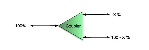
First we should define what these passive devices are. An optical coupler is a passive device that can split or combine signals in optical fibers. They are named by the number of inputs and outputs, so a splitter with one input and 2 outputs is a 1×2 fiber splitter, and a PON splitter with one input and 32 outputs is 1×32 splitter. Some PON splitters have two inputs so it would be a 2X32. Here is a table of typical losses for splitters.

Splitter Ratio

Important Note! Mode Conditioning can be very important to testing couplers. Some of the ways they are manufactured make them very sensitive to mode conditioning, especially multimode but even singlemode couplers. Singlemode couplers should always be tested with a small loop in the launch cable (tied down so it does not change and set the 0dB reference with the loop.) Multimode couplers should be mode conditioned by a mandrel wrap or similar to ensure consistency.

Let’s start with the simplest type. Shown below is a simple 1X2 splitter with one input and two outputs. Basically, in one direction it splits the signal into 2 parts to couple to two fibers. If the split is equal, each fiber will carry a signal that is 3dB less than the input (3dB being a factor of two) plus some excess loss in the coupler and perhaps the connectors on the splitter module. Going the other direction, signals in either fiber will be combined into the one fiber on the other side. The loss is this direction is a function of how the coupler is made. Some couplers are made by twisting two fibers together and fusing them in high heat, so the coupler is really a 2X2 coupler in which case the loss is the same (3dB plus excess loss) in either direction. Some splitters use optical integrated components, so they can be true splitters and the loss in each direction may different.
coupler

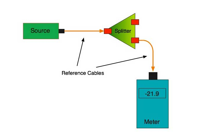
So for this simple 1X2 splitter, how do we test it? Simply follow the same directions for a double-ended loss test. Attach a launch reference cable to the test source of the proper wavelength (some splitters are wavelength dependent), calibrate the output of the launch cable with the meter to set the 0dB reference, attach to the source launch to the splitter, attach a receive launch cable to the output and the meter and measure loss. What you are measuring is the loss of the splitter due to the split ratio, excess loss from the manufacturing process used to make the splitter and the input and output connectors. So the loss you measure is the loss you can expect when you plug the splitter into a cable plant.

To test the loss to the second port, simply move the receive cable to the other port and read the loss from the meter. This same method works with typical PON splitters that are 1 input and 32 outputs. Set the source up on the input and use the meter and reference cable to test each output port in turn.

What about the other direction from all the output ports? (In PON terms, we call that upstream and the other way from the 1 to 32 ports direction downstream.) Simply reverse the direction of the test. If you are tesing a 1X2 splitter, there is just one other port to test, but with a 1X32, you have to move the source 32 times and record the results on the meter.
fiber splitter

What about multiple input and outputs, for example a 2X2 coupler? You would need to test from one input port to the two outputs, then from the other input port to each of the two outputs. This involves a lot of data sometimes but it needs to be tested.

There are other tests that can be performed, including wavelength variations (test at several wavelengths), variations among outputs (compare outputs) and even crosstalk (put a signal on one output and look for signal on other outputs.)

Once installed, the splitter simply becomes one source of loss in the cable plant and is tested as part of that cable plant loss for insertion loss testing. Testing splitters with an OTDR is not the same in each direction。

Other Passive Devices

There are other passive devices that require testing, but the test methods are similar.

Fiber optic switches are devices that can switch an input to one of several outputs under electronic control. Test as you would the splitter as shown above. Switches may be designed for use in only one direction, so check the device specifications to ensure you test in the proper direction. Switches may also need testing for consistency after multiple switch cycles and crosstalk.

Attenuators are used to reduce signal levels at the receiver to prevent overloading the receiver. There is a page on using attenuators that you should read. If you need to test an attenuator alone, not part of a system, use the test for splitters above by using the attenuator to connect the launch and receive cables to see if the loss is as expected.

Wavelength-division multiplexers can be tricky to test because they require sources at a precise wavelenth and spectral width, but otherwise the test procedures are similar to other passive components.

Fiber optic couplers or splitters are available in a wide range of styles and sizes to split or combine light with minimal loss. All couplers are manufactured using a very simple proprietary process that produces reliable, low-cost devices. They are physically rugged and insensitive to operating temperatures. Couplers can be fabricated in custom fiber lengths and/or with terminations of any type.

Fiberstore offers a wide variety of collimation and coupling components that can be used to effectively collimate or couple light out of and into FC/PC, FC/APC, or SMA terminated fiber. Optical isolators help protect sensitive laser sources and components from back reflections while fiber couplers, WDMs, circulators, and switches are the fundamental tools to creating fiber based optical circuits. We also offer a line of components for optogenetics applications, including fiber optic cannulae, patch cords, and light sources.