Empowering Your 800G Networks with MTP/MPO Fiber Cables

In the era of ultra-high-speed data transmission, MTP/MPO cables have become a key player, especially in the context of 800G networks. In essence, MTP/MPO cables emerge as catalysts for the evolution toward 800G networks, offering a harmonious blend of high-density connectivity, reliability, and scalability. This article will delve into the advantages of MTP/MPO cables in 800G networks and provide specific solutions for constructing an 800G network, offering valuable insights for upgrading your existing data center.

Challenges Faced in 800G Data Transmission

As a critical hub for storing and processing vast amounts of data, data centers require high-speed and stable networks to support data transmission and processing. The 800G network achieves a data transfer rate of 800 Gigabits per second (Gbps) and can meet the demands of large-scale data transmission and processing in data centers, enhancing overall efficiency.

Therefore, many major internet companies are either constructing new 800G data centers or upgrading existing data centers from 100G, 400G to 800G speeds. However, the pursuit of 800G data transmission faces numerous complex challenges that necessitate innovative solutions. Here, we analyze the intricate obstacles associated with achieving ultra-fast data transmission.

Insufficient Bandwidth & High Latency

The 800G network demands extensive data transmission, placing higher requirements on bandwidth. It necessitates network equipment capable of supporting greater data throughput, particularly in terms of connection cables. Ordinary optical fibers typically consist of a single fiber within a cable, and their optical and physical characteristics are inadequate for handling massive data, failing to meet the high-bandwidth requirements of 800G.

While emphasizing high bandwidth, data center networks also require low latency to meet end-user experience standards. In high-speed networks, ordinary optical fibers undergo more refraction and scattering, resulting in additional time delays during signal transmission.

Limited Spatial Layout

The high bandwidth requirements of 800G networks typically come with more connection ports and optical fibers. However, the limited space in data centers or server rooms poses a challenge. Achieving high-density connections requires accommodating more connection devices in the constrained space, leading to crowded layouts and increased challenges in space management and design.

Complex Network Architecture

The transition to an 800G network necessitates a reassessment of network architecture. Upgrading to higher data rates requires consideration of network design, scalability, and compatibility with existing infrastructure. Therefore, the cabling system must meet both current usage requirements and align with future development trends. Given the long usage lifecycle of cabling systems, addressing how to match the cabling installation with multiple IT equipment update cycles becomes a challenging problem.

High Construction Cost

Implementing 800G data transmission involves investments in infrastructure and equipment. Achieving higher data rates requires upgrading and replacing existing network equipment and cabling management patterns, incurring significant costs. Cables, in particular, carry various network devices, and their required lifecycle is longer than that of network equipment. Frequent replacements can result in resource wastage.

Effectively addressing these challenges is crucial to unlocking the full potential of a super-fast, efficient data network.

Unlocking 800G Power: MTP/MPO Cables’ Key Advantages

The significance of MTP/MPO cables in high-speed networks, especially in 800G networks, lies in their ability to manage the escalating data traffic efficiently. The following are key advantages of MTP/MPO cables:

High Density, High Bandwidth

MTP/MPO cables adopt a high-density multi-fiber design, enabling the transmission of multiple fibers within a relatively small connector. This design not only provides ample bandwidth support for data centers, meeting the high bandwidth requirements of an 800G network, but also helps save space and supports the high-density connection needs for large-scale data transfers.

Additionally, MTP/MPO cables exhibit excellent optical and mechanical performance, resulting in low insertion loss in high-speed network environments. By utilizing a low-loss cabling solution, they effectively contribute to reducing latency in the network.

Flexibility and Scalability

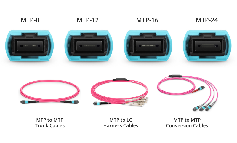
MTP/MPO connectors come in various configurations, accommodating different fiber counts (8-core, 12-core, 16-core, 24-core, etc.), supporting both multimode and single-mode fibers. With trunk and breakout designs, support for different polarities, and male/female connector options, these features allow seamless integration into various network architectures. The flexibility and scalability of MTP/MPO connectors enable them to adapt to evolving network requirements and facilitate future expansions, particularly in the context of 800G networks.

Efficient Maintenance

The high-density and compact design of MTP/MPO cables contribute to saving rack and data room space, enabling data centers to utilize limited space resources more efficiently. This, in turn, facilitates the straightforward deployment and reliable operation of 800G networks, reducing the risks associated with infrastructure changes or additions in terms of cost and performance. Additionally, MTP/MPO cables featuring a Plenum (OFNP) outer sheath exhibit fire resistance and low smoke characteristics, minimizing potential damage and saving on cabling costs.

Scaling the 800G Networks With MTP/MPO Cables

In the implementation of 800G data transmission, the wiring solution is crucial. MTP/MPO cables, as a key component, provide reliable support for high-speed data transmission. FS provides professional solutions for large-scale data center users who require a comprehensive upgrade to 800G speeds. Aim to rapidly increase data center network bandwidth to meet the growing demands of business.

Newly Built 800G Data Center

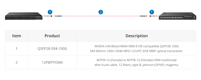
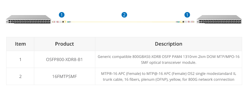
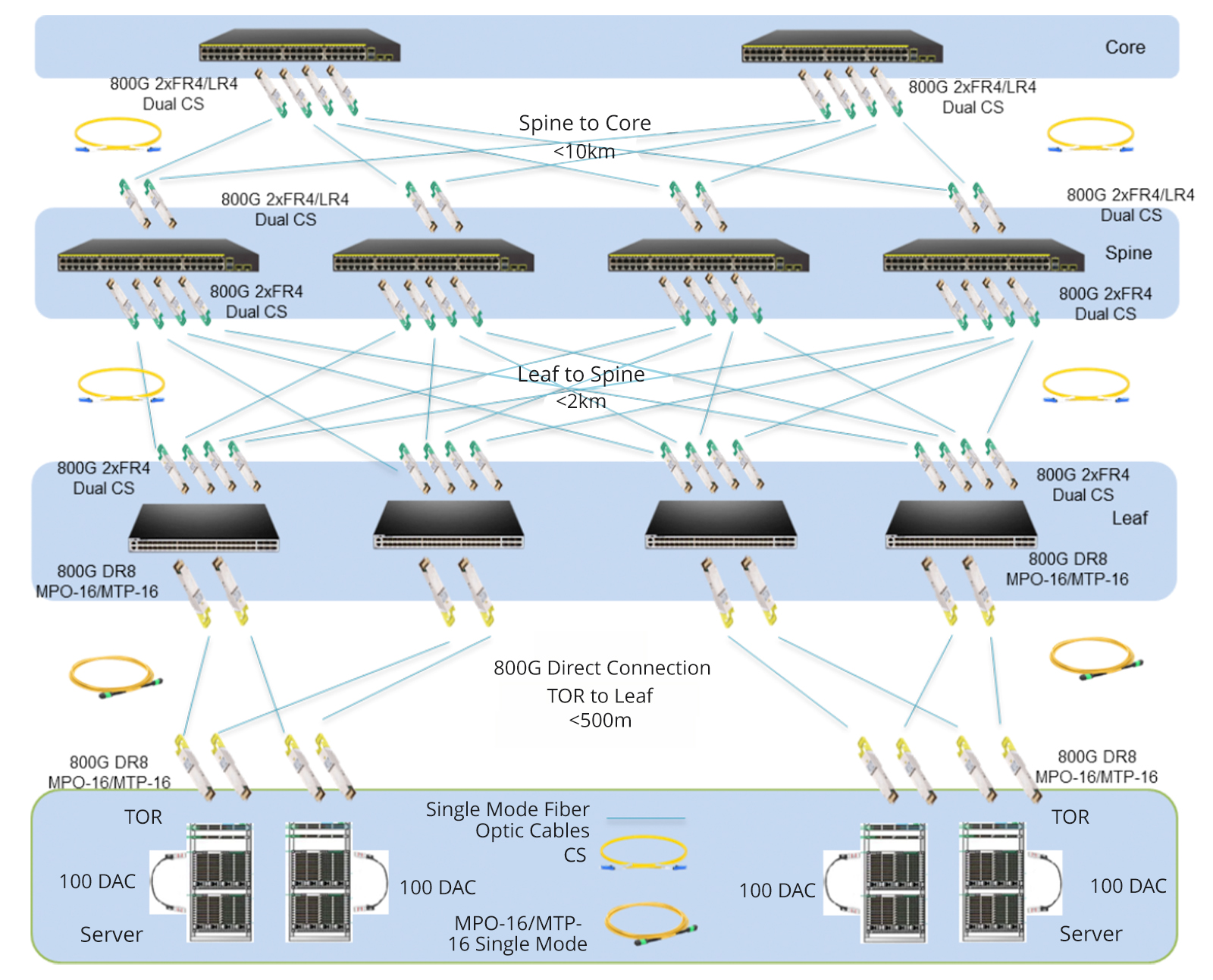
Given the rapid expansion of business, many large-scale internet companies choose to build new 800G data centers to enhance their network bandwidth. In these data centers, all network equipment utilizes 800G switches, combined with MTP/MPO cables to achieve a direct-connected 800G network. To ensure high-speed data transmission, advanced 800G 2xFR4/2xLR4 modules are employed between the core switches and backbone switches, and 800G DR8 modules seamlessly interconnect leaf switches with TOR switches.

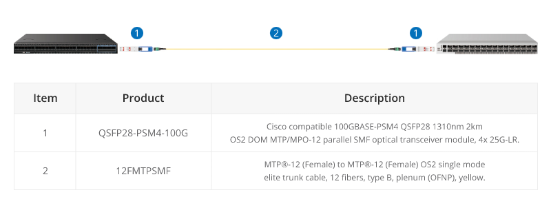
To simplify connections, a strategic deployment of the 16-core MTP/MPO OS2 trunk cables directly connects to 800G optical modules. This strategic approach maximally conserves fiber resources, optimizes wiring space, and facilitates cable management, providing a more efficient and cost-effective cabling solution for the infrastructure of 800G networks.

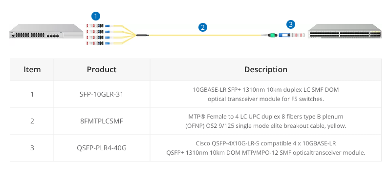
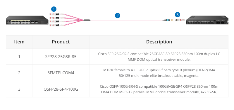
Upgrade from 100G to 800G

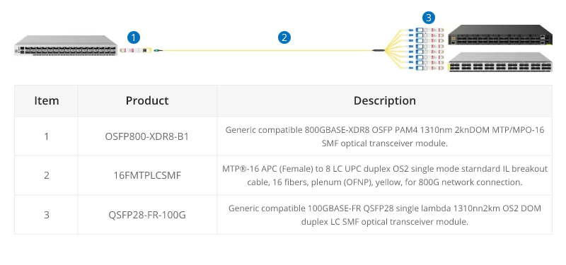
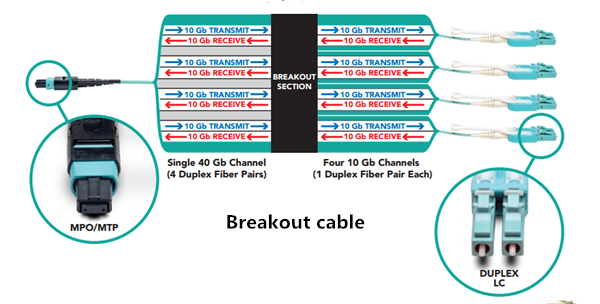
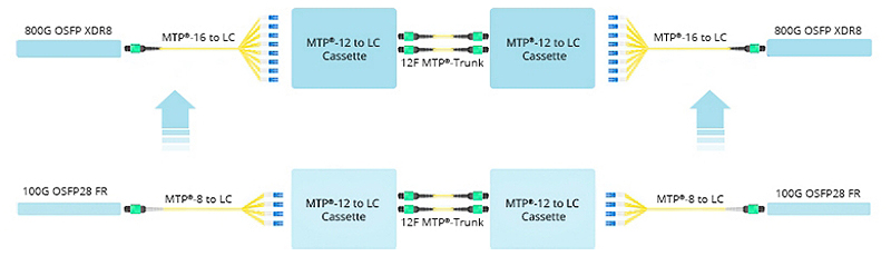
Certainly, many businesses choose to renovate and upgrade their existing data center networks. In the scenario below, engineers replaced the original 8-core MTP/MPO-LC breakout cable with the 16-core version, connecting it to the existing MTP cassettes. The modules on both ends, previously 100G QSFP28 FR, were upgraded to 800G OSFP XDR8. This seamless deployment migrated the existing structured cabling to an 800G rate. It is primarily due to the 16-core MTP/MPO-LC breakout cable, proven as the optimal choice for direct connections from 800G OSFP XDR8 to 100G QSFP28 FR or from 800G QSFP-DD/OSFP DR8 to 100G QSFP28 DR.

In short, this solution aims to increase the density of fiber optic connections in the data center and optimize cabling space. Not only improves current network performance but also takes into account future network expansion.

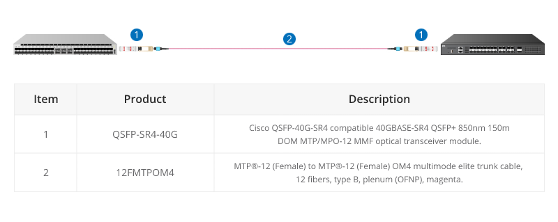
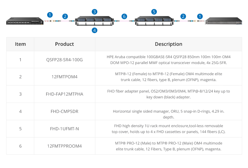
Elevating from 400G to the 800G Network

How to upgrade an existing 400G network to 800G in data centers? Let’s explore the best practices through MTP/MPO cables to achieve this goal.

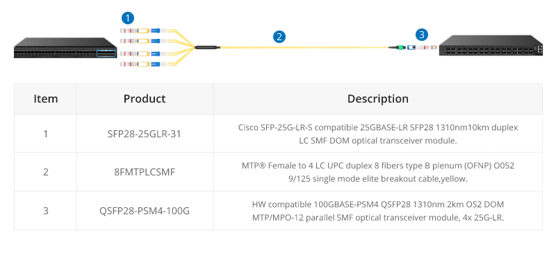
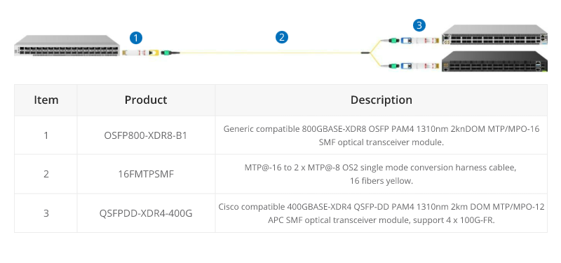
Based on the original 400G network, the core, backbone, and leaf switches have all been upgraded to an 800G rate, while the TOR (Top of Rack) remains at a 400G rate. The core and backbone switches utilize 800G 2xFR4/2xLR4 modules, the leaf switches use 800G DR8 modules, and the TOR adopts 400G DR4 modules. Deploying two 12-core MTP/MPO OS2 trunk cables in a breakout configuration between the 400G and 800G optical modules facilitates interconnection.

This cabling solution enhances scalability, prevents network bottlenecks, reduces latency, and is conducive to expanding bandwidth when transitioning from lower-speed to higher-speed networks in the future. Additionally, this deployment retains the existing network equipment, significantly lowering cost expenditures.

ItemProductDescription
1OSFP-DR8-800GNVIDIA InfiniBand MMS4X00-NM compatible OSFP 800G DR8 PAM4 2x DR4 1310nm 500m DOM dual MPO-12/APC NDR SMF optical transceiver, finned top.
2OSFP800-XDR8-B1Generic compatible 800GBASE-XDR8 OSFP PAM4 1310nm 2km DOM MTP/MPO-16 SMF optical transceiver module.
3OSFP-2FR4-800GNVIDIA InfiniBand MMS4X50-NM compatible OSFP 800G 2FR4 PAM4 1310nm 2km DOM dual LC duplex/UPC NDR SMF optical transceiver, finned top.
416FMTPSMFMTP®-16 APC (Female) to MTP®-16 APC (Female) OS2 single mode standard IL trunk cable, 16 fibers, plenum (OFNP), yellow, for 800G network connection.
516FMTPLCSMFMTP®-16 APC (Female) to 8 LC UPC duplex OS2 single mode standard IL breakout cable, 16 Fibers, plenum (OFNP), yellow, for 800G network connection.
612FMTPSMFMTP®-12 (Female) to MTP®-12 (Female) OS2 single mode elite trunk cable, 12 fibers, type B, plenum (OFNP), yellow.

For more specific 800G connectivity solutions, please refer to 800G MTP/MPO Cabling Guide.

Conclusion

Ultimately, the diverse range of MTP/MPO cable types provides tailored solutions for different connectivity scenarios in 800G networks. As organizations navigate the complexities of high-speed data transmission, MTP/MPO cables stand as indispensable enablers, paving the way for a new era of efficient and robust network infrastructures.

How FS Can Help

The comprehensive networking solutions and product offerings not only save costs but also reduce power consumption, delivering higher value. Considering an upgrade to 800G for your data center network? FS tailors customized solutions for you. Don’t wait any longer—Register as an FS website member now and enjoy free technical support.

Choosing the Right MTP/MPO Cable: A Guide to Core Numbers

Choosing the right MTP/MPO cable ensures efficient and reliable data transmission in today’s fast-paced digital world. With the increasing demand for high-speed connectivity, it is essential to understand the importance of core numbers in MTP/MPO cables. In this guide, we will explore the significance of core numbers and provide valuable insights to help you decide when selecting the right MTP/MPO cable for your specific needs. Whether setting up a data center or upgrading your existing network infrastructure, this article will serve as a comprehensive resource to assist you in choosing the right MTP/MPO cable.

What is an MTP/MPO cable

An MTP/MPO cable is a high-density fiber optic cable that is commonly used in data centers and telecommunications networks. It is designed to provide a quick and efficient way to connect multiple fibers in a single connector.

MPO and MTP cables have many attributes in common, which is why both are so popular. The key defining characteristic is that these cables have pre-terminated fibers with standardized connectors. While other fiber optic cables have to be painstakingly arrayed and installed at each node in a data center, these cables are practically plug-and-play. To have that convenience while still providing the highest levels of performance makes them a top choice for many data center applications.

How Many Types of MTP/MPO cables

MTP/MPO cables consist of connectors and optical fibers ready to connect. When it comes to types, MTP/MPO fiber cables fall on MTP/MPO trunk cables and MTP/MPO harness/breakout cables.

MTP/MPO trunk cables

MTP/MPO trunk cables, typically used for creating backbone and horizontal interconnections, have an MTP/MPO connector on both ends and are available from 8 fibers up to 48 in one cable.

MTP/MPO Harness/Breakout Cables

Harness/Breakout cables are used to break out the MTP/MPO connector into individual connectors, allowing for easy connection to equipment. MTP/MPO conversion cables are used to convert between different connector types, such as MTP to LC or MTP to SC.

The MTP/MPO cables also come in different configurations, such as 8-core, 12-core, 16-core, 32-core, and more, depending on the specific needs of the application. This flexibility in configurations enables users to tailor their choices according to the scale and performance requirements of their networks or data centers. As technology advances, the configurations of MTP/MPO cables continually evolve to meet the increasing demands of data transmission.

How to Choose MTP/MPO cables

Selecting the appropriate core number for MTP/MPO cables resonates throughout the efficiency and performance of networks. In this section, we’ll delve into the decision-making factors surrounding core numbers in cables.

Network Requirements and Data Transmission Goals

Different network applications and data transmission needs may require varying numbers of cores. High-density data centers might necessitate more cores to support large-capacity data transmission, while smaller networks may require fewer cores.

Compatibility with Existing Infrastructure

When choosing the core number for MTP/MPO cables, compatibility with existing infrastructure is crucial. Ensuring that the new cables match existing fiber optic equipment and connectors helps avoid unnecessary compatibility issues.

Consideration for Future Scalability

As businesses grow and technology advances, future network demands may increase. Choosing MTP/MPO cables with a larger number of cores allows for future expansion and upgrades.

Budget and Resource Constraints

Budget and resources also play a role in core number selection. Cables with a larger number of cores tend to be more expensive, while cables with fewer cores may be more cost-effective. Therefore, finding a balance between actual requirements and the available budget is essential.

MTP/MPO Cabling Guide to Core Numbers

40G MTP/MPO Cabling

A 12-fiber MTP/MPO connector interface can accommodate 40G, which is usually used in a 40G data center. The typical implementations of MTP/MPO plug-and-play systems split a 12-fiber trunk into six channels that run up to 10 Gigabit Ethernet (depending on the length of the cable). 40G system uses a 12-fiber trunk to create a Tx/Rx link, dedicating 4 fibers for 10G each of upstream transmit, and 4 fibers for 10G each of downstream receive.

40G-10G Connection

In this scenario, a 40G QSFP+ port on the FS S5850 48S6Q switch is split up into 4 10G channels. An 8-fiber MTP-LC harness cable connects the 40G side with its MTP connector and the four LC connectors link with the 10G side.

40G-40G Connection

As shown below, a 12-fiber MTP trunk cable is used to connect two 40G optical transceivers to realize the 40G to 40G connection between the two switches. The connection method can also be applied to a 100G-100G connection.

40G Trunk Cabling

24 Fibers MTP® to MTP® Interconnect Conversion Harness Cable is designed to provide a more flexible multi-fiber cabling system based on MTP® products. Unlike MTP® harness cable, MTP® conversion cables are terminated with MTP® connectors on both ends and can provide more possibilities for the existing 24-fiber cabling system. The 40/100G MTP® conversion cables eliminate the wasted fibers in the current 40G transmission and upcoming 100G transmission. Compared to purchasing and installing separate conversion cassettes, using MTP® conversion cables is a more cost-effective and lower-loss option.

100G MTP/MPO Cabling

QSFP28 100G transceivers using 4 fiber pairs have an MTP/MPO 12f port (with 4 unused fibers). Transmission for short distances (up to 100m) could be done most cost-effectively over multimode fiber using SR4 transmission. Longer distances over single mode use PSM4 transmission over 8 fibers. Transmission over 4 fiber pairs enables both multimode and single-mode transceivers to be connected 1:4 using MPO-LC 8 fiber breakout cables. One QSFP28 100G can connect to four SFP28 25G transceivers.

100G SR4 Parallel BASE-8 over Multimode Fibre

QSFP28 100G SR4 are often connected directly together due to their proximity within switching areas.

Equally QSFP28 SR4 are often connected directly to SFP28 25G ports within the same rack. For example, from a switch 100G port to four different servers with 25G ports.

The 12-core MTP/MPO cables can also be used for 100G parallel to parallel connection. Through the use of MTP patch panels, network reliability is enhanced, ensuring the normal operation of other channels even if a particular channel experiences a failure. Additionally, by increasing the number of parallel channels, it can meet the continuously growing data demands. This flexibility is crucial for adapting to future network expansions.

100G PMS4 Parallel BASE-8 over Singmode Fibre

QSFP28 100G PMS4 are often connected directly together due to their proximity within switching areas.

Equally QSFP28 ports are often connected directly to SFP28 25G ports within the same rack. For example, from a switch 100G port to four different servers with 25G ports.

200G MTP/MPO Cabling

Although most equipment manufacturers (Cisco, Juniper, Arista, etc) are bypassing 200G and jumping from 100G to 400G, there are still some 200G QSFP-DD transceivers on the market, like FS QSFP56-SR4-200G and QSFP-FR4-200G.

200G-to-200G links

MTP (MPO) 12 fiber enables the connection of 2xQSFP56-SR4-200G to each other.

400G MTP/MPO Cabling

MTP/MPO cables with multi-core connectors are used for optical transceiver connection. There are 4 different types of application scenarios for 400G MTP/MPO cables. Common MTP/MPO patch cables include 8-fiber, 12-core, and 16-core. 8-core or 12-core MTP/MPO single-mode fiber patch cable is usually used to complete the direct connection of two 400G-DR4 optical transceivers. 16-core MTP/MPO fiber patch cable can be used to connect 400G-SR8 optical transceivers to 200G QSFP56 SR4 optical transceivers, and can also be used to connect 400G-8x50G to 400G-4x100G transceivers. The 8-core MTP to 4-core LC duplex fiber patch cable is used to connect the 400G-DR4 optical transceiver with a 100G-DR optical transceiver.

For more specific 400G connectivity solutions, please refer to FS 400G MTP/MPO Cabling.

800G MTP/MPO Cabling Guide

In the higher-speed 800G networking landscape, the high density, high bandwidth, and flexibility of MTP/MPO cables have played a crucial role. Leveraging various branching or direct connection schemes, MTP/MPO cables are seamlessly connected to 800G optical modules, 400G optical modules, and 100G optical modules, enhancing the richness and flexibility of network construction.

800G Connectivity with Direct Connect Cabling

16 Fibers MTP® trunk cable is designed for 800G QSFP-DD/OSFP DR8 and 800G OSFP XDR8 optics direct connection and supporting 800G transmission for Hyperscale Data Center.

800G to 8X100G Interconnect

16 fibers MTP®-LC breakout cables are optimized for 800G OSFP XDR8 to 100G QSFP28 FR, 800G QSFP-DD/OSFP DR8 to 100G QSFP28 DR optics direct connection, and high-density data center applications.

800G to 2X400G Interconnect

16 fiber MTP® conversion cable is designed to provide a more flexible multi-fiber cabling system based on MTP® products. Compared to purchasing and installing separate conversion cassettes, using MTP® conversion cables is a more cost-effective and lower-loss option. In the network upgrade from 400G to 800G, the ability to directly connect an 800G optical module and two 400G optical modules provides a more efficient use of cabling space, resulting in cost savings for cabling.

Conclusion

In a word, the choice of core number for MTP/MPO cables depends on the specific requirements of the network application. Matching the core number with the requirements of each scenario ensures optimal performance and efficient resource utilization. A well-informed choice ensures that your MTP/MPO cable not only meets but exceeds the demands of your evolving connectivity requirements.

How FS Can Help

As a global leader in enterprise-level ICT solutions, FS not only offers a variety of MTP/MPO cables but also customizes exclusive MTP/MPO cabling solutions based on your requirements, helping your data center network achieve a smooth upgrade. In the era of rapid growth in network data, the time has come to make a choice – FS escorts your data center upgrade. Register as an FS website member and enjoy free technical support.

Options Upgrading to 100G Connection

With growing data traffic volume in recent years, the existing 10Gb/s optical networks are becoming saturated, which drive the great need for 40G and 100G networks. In turn, 100G network also can bring benefits for network operators. For example, 100G network can reduce the cost per bit, improve the utilization of existing fiber and reduce the network delay. This post intends to explore the options to get 100G connection.

100G Connectivity Challenges

As we all know, existing 10G network use two fibers in either a SC duplex or a LC duplex connector to realize data transmission. But different from this transmit type, data in 100G network often get multiplexed and transferred over the 4 or 10 parallel wavelengths on a single fiber, which means the lanes of the two kinds of networks are a little different. This is one problem that should be considered when deploy 100G connections.

Except for that, the cost is another problem needed to be resolved. No matter the 40G or 100G, both of them require more fibers and optical connectors, resulting in increasing cost. For example, 40G Ethernet and 100G Ethernet over multimode fiber uses parallel optics at 10 Gb/s per lane. One lane uses one fiber for each direction of transmission. So 40G Ethernet requires eight fibers. And 100G Ethernet requires 20 fibers.

Options Upgrading to 100G Connections
Option One: Upgrading to 100G Connections with DWDM Mux

With the boom application of cloud services, telemedicine, video on demand, etc, data rate migration encompassing the entire optical network. Therefore, some core networks have deployed DWDM to release this bandwidth explosion. With large capacity transmission ability, DWDM technology offers a cost-effective method to meet the bandwidth requirements.

Complementing the existing 10Gbps DWDM system with 100Gbps upgrades

In many cases, to avoid the high cost and save cost, some operators often use one DWDM Mux to add one or more 100G services into the same fiber. The picture is showing one of that cases. In this case, 10G and 100G services are multiplexed by two separated 100GHz DWDM MUX. Owing to the 100G services are easy to be affected by dispersion, so the optical amplifier and DCM (Dispersion Compensation Module) are added in the links to boost the signal power. Then the 10G and 100G services are bundled together by using the interleaver which is an optical router often used in DWDM system. And finally the 100G connection is achieved.

Option Two: Upgrading to 100G Connections with MTP Assemblies

Nowadays there are various products on the market to support 100G connections. The most often used is 100G CFP, 100G QSFP28 and MTP optical cables. For many network operators, the option one that uses 100GHz DWDM Mux, optical amplifier, DCM and 100G optical transceivers maybe a little expensive. However, except for using DWDM Mux to achieve 100G connections, there is another choice. It is to achieve 100G connections with MTP assemblies.

100G Connection Deployment

In this connection, the 100G connection can be realized by using a MTP cord with a 24-fiber MTP connector on one end and two 12-fiber MTP connectors on the other end.

Notes: this simple chart just illustrates a short distance 100G connection.

Besides, since 10G connections usually use common fiber optic cables with LC or SC connectors, and the 40G connections use 12-fiber MTP cables, while 100G connections utilize 24-fiber MTP connections. Therefore, migrating from 10G/40G to 100G can be realized. Look at the basic 10G and 40G deployment scenario.

10G 40G network deployment

From the picture we can see, the similarities of these connections are that they are using MTP cables. Just change the cable types and then migrating from 10G to 40G and 100G are possible.

Summary

100G connection is the trend in the future data centers. This post introduces two options to achieve 100G connections with existing optical components. According to different requirements, you can choose a suitable solution. FS.COM supplies various optical components to meet diverse applications in data centers and enterprise networks. If you want to know more details about 100G networks, please visit our website www.fs.com.

Effective Solutions for 10G/40G Connectivity

As the growing demand for faster access to larger volumes of data, coupled with emerging high-speed network standards and rapidly advancing technology, fiber optic cables and cabling components have become a very popular element in data centers and high-speed networks. And when 10G fiber is the norm in most data centers today, the 40G fiber is also becoming commonplace. In this article, three effective solutions for 10G/40G connectivity will be introduced.

Breakout Cabling Solutions

A breakout cable is a multi-strand cable which is divided into different specification cables. For example, a 40G breakout cable has four 10G duplex cables totaling eight strands, while a 100G breakout cable has 10 duplex cables and 20 strands.

How Does Breakout Cable Work?

To understand how breakout cabling solutions work, take integrating 10Gb servers into a 40G network for example. For each port on the switch, an MTP/MPO breakout cable which has an MPO/MTP connector on one end and four duplex LC connectors on the other end is needed. The MPO/MTP connector is plugged into the transceiver that connects with 40G switch and each duplex LC connector plugs into a 10G port on each server. If the switch has up to 32 40G ports, up to 128 10G devices can be connected to it using breakout cables.

breakout-cabling-solution

Advantages

This breakout cabling solution enables slower equipment to be connected to higher-speed equipment successfully, such as the 10G servers and 40G switch in our example. Up to 128 10G devices can be connected to a 32-port 40G switch.

MTP Cassettes Solutions

MTP cassette provide secure transition between MTP and LC or SC discrete connectors. They are used to interconnect MTP backbones with LC or SC patching. Supporting various network cabling standards, the cassettes are easy to mix, match, add and replace as the connectivity needs grow or change.

How Does MTP Cassette Work?

Fiber cassettes are the key to modular systems. Available in multiple variations, the cassettes allow users to interconnect different fiber speeds simply by plugging standard LC cables into one side of the cassette and one or more standard MPO/MTP cables into the other side.

modular-patch-panel-solution

For 10G connectivity, MTP/MPO cassettes are used to connect 10G device to 10G device, especially when the distance between two devices is too long. And for 40G connectivity, MPO/MTP cassette is used to connect 10G device to 40G device. Modular patch panel solutions offer users an easy-to-use solution that works with the equipment of today and can easily be transitioned for the networks of tomorrow.

Advantages

MTP cassette solution also has many advantages. First, this solution offers flexibility and scalability for network upgrade. Second, with fiber cassettes, this solution allows users to manage cables in any direction—horizontal or vertical, front or back. Finally, by managing varying port densities and speeds in a single high-density patch panel, users can save valuable rack space and data center costs.

Fiber Breakout Panels Solutions

Fiber breakout panels are ready for plug-and-play deployment out of the box. They provide increased access between ports, thus enabling the ease of moves, adds, and changes of cables. It’s the increased access that help fiber breakout panels offer a cost saving, simple and efficient cable management solution for future high-speed network connection.

How Does Breakout Panels Work?

Fiber breakout panels offer a simple, cost-effective alternative to breakout cables. To understanding how it works, let’s take one of 40G QSFP+ breakout patch panel for example. The 96 fibers MTP-LC 1U Ultra Density 40G QSFP+ breakout patch panel has 48 duplex LC ports front and 12 MTP Elite rear ports. When it’s installed, the 40G QSFP ports with MTP fiber cable will be connected to the back of the panel, and then LC fiber cables will be linked to the LC port. This 40G QSFP breakout panel logically groups the ports in 4 duplex LC ports, and is available for single-mode or multimode applications.

multimode-singlemode-fiber-breakout-panel

Advantages

Breakout panels solution can connect different equipment such as 10G, 40G and 100G, offering more flexibility for network cabling. Besides, as the breakout panels are pre-terminated, they can be easily installed and help save installation time.

Conclusion

With increasingly higher network speeds always just around the corner, network build and upgrade also get much attention. Choosing suitable connectivity solution for 10G/40G connectivity which allows you to meet your current connectivity needs while simultaneously investing in your future also should be attached more importance. The contents above give an explanation of three cabling solutions. Hope it may help you.

LC Uniboot Fiber Patch Cable – An Optimum Cable Management Option

With the ever lasting advancement of networking technology, there comes an increasing demand for data centers to accommodate higher density cables and more bandwidth. However, it is generally acknowledged that data centers are often with limited space. Then how to handle those massive cables in such circumstances becomes a vital issue. This article will introduce the LC uniboot fiber patch cable, an optimum alternative for cable management that is designed to deliver maximum connectivity performance.

LC Uniboot Fiber Patch Cables Description

LC uniboot fiber patch cable consists of two LC connectors that wrapped by a common housing with one boot. It is terminated on a single, round, two-fiber cable to achieve duplex data transmission. LC uniboot patch cable allows for up to 68% savings in cabling volume due to a compact design, and it can ensure easier maintenance and operability with tool-less field reversible polarity and color identification. All the features presented by LC uniboot fiber patch cable make it an ideal option for high density network environment.

LC uniboot fiber patch cable

Comparison Between LC Uniboot Fiber Patch Cables and Standard Ones

LC fiber optic connectors offer higher density and better performance in most environments when compared with other fiber optic connectors, making it a reliable and popular choice for many applications and equipment. This can explain why uniboot fiber patch cables are terminated with specially designed LC connectors. The innovative LC uniboot fiber patch cable, with its unique structure and compact design, performs even better than standard LC fiber patch cables in high density cabling environment. Here, we present the obvious differences between the LC uniboot patch cable and the standard LC fiber patch cable in the following picture.

LC uniboot fiber patch cable vs.standard fiber patch cable

Features of LC Uniboot Fiber Patch Cables

Genarally, there are three primary features concerning the uniboot fiber patch cables:

Adjustable Pitch—the unique style of the clip allows the LC Connectors to easily adjust for the increasing demand of a 5.25 pitch, as well as the standard 6.25 pitch. Eliminating the requirement for hybrid patch cables.

Reverse Polarity—with a few simple steps, the connectors polarity of the LC uniboot fiber patch cables can be reversed at will without connector re-termination.

Quick Release Latch—the latch of LC uniboot fiber patch cable allows for the quick and easy release of this connector from the adapter panel, which makes great sense in the growing trend of high density applications.

What LC Uniboot Fiber Patch Cables Can Achieve?

As we have mentioned previously, LC uniboot fiber patch cables are especially vital to space sensitive data centers and high density cabling environments, so what exactly we can benefit from deploying LC uniboot fiber patch cables?

Cable Congestion Reduction

With two fibers for duplex transmission firmly enclosed in a single cable, LC uniboot fiber patch cable effectively cuts down the cable count up to 50% compared with the standard LC duplex patch cords. Thus the space requirement of cabling can be significantly reduced by it, naturally result in less chance of cable congestion in data centers.

Effective Polarity Reversal

Changing the polarity of a standard LC duplex fiber patch cable may be annoying to many data center operators, especially when there happens to be a high density cabling system. This is sort of a time and energy consuming task since some minor mistakes could lead to various troubles. However, with LC uniboot patch cable, the polarity replacement can be much easier even without any additional tools. In terms of different types of LC uniboot patch cables, the polarity reversal steps may vary. We just illustrate two most used ones as follows.

LC uniboot polarity reversal

Conclusion

To address the increasing demand for high density applications and smaller fiber cable, the LC uniboot fiber patch cable is designed to help cut down cabling space and provide more effective polarity reversal solution, and to streamline cable management and logistics. Without doubt, LC uniboot fiber patch cable is the savior of popularized high-density cabling system. Hope this article could help you to choose the right LC uniboot patch cable for your applications, and for more products information and solutions, please visit www.fs.com.

Pre-Terminated Cabling System—An Ideal Solution for Data Centers

When designing and implementing their high-density networks, most data center managers and operators are inclined to options which are more sustainable and environmentally sound. They always expect systems to provide high performance and reliability for maximum network uptime over the long term. Since the demand for higher bandwidth and flexibility for future growth never ending, network administrators now are seeking to the network’s physical media infrastructure to achieve these goals. And the growing adoption of pre-terminated cabling system serves as one of the trend, that is what we will explain in this article.

What Is Pre-Terminated Cabling?

Then what the pre-terminated cabling system refers to and how it differs from field terminated one? In fact, pre-terminated cables go through the same procedures as field terminated cables, but these steps are taken at the manufacturer’s facility or cable assembly house and delivered to the job site with the connectors already terminated, properly polished, and the entire cable assembly tested on either both or one end. Which helps to eliminate the necessity for on-site field termination. Compared with field terminated cabling products, pre-terminated fiber cable assemblies are more convenient and flexible. They are most suited for network installations that are planned well in advance, taking into account both current and future requirements.

What Pre-Terminated Cabling System Can Achieve?

Installing and connecting your cable infrastructure in the data center consists of various labor intensive tasks. And manual field terminations, troubleshooting, and error corrections also extended deployment times, higher installation costs and increased downtime. However, with the deployment of pre-terminated cabling system, you are supposed to benefit from it with the following aspects:

  • Installation time and costs are substantially reduced.
  • Material reductions of 50 percent or more are typical when using pre-terminated systems rather than traditional systems.
  • Network performance and reliability are assured due to in-factory testing and validation of components.
  • Modular components at the physical layer are reusable. They can be disassembled and repurposed to accommodate moves, adds and changes, which provides greater flexibility and portability, as well as a clear migration path to support new technologies and applications as an organization grows and requirements change and evolve.
  • Pre-terminated installations are more precisely planned, which results in a neater, cleaner appearance, as well as faster and easier cable management, maintenance and troubleshooting.
Common Pre-Terminated Fiber Cables

It is undeniable that pre-terminated fiber cabling system indeed offers a constructive and ideal solution to data center management and maintenance. Here in this part, we will further introduce some most commonly employed pre-terminated fiber cables, including fiber patch cables, fiber optic pigtails and MTP/MPO pre-terminated cables.

Fiber Patch Cables

As one of the most used components in fiber optic networks, fiber patch cables help to ensure a reliable temporary fiber optic interconnection. There exists a wide range of fiber patch cables on the market, available in single-mode and multimode versions with PVC, LSZH, OFNP or armored jacket. And connection type options involve LC, FC, SC, ST, MU, MTRJ and E2000 pre-terminated in duplex or simplex fiber. Fiber patch cables are suitable for all kinds of fiber optic connectivity applications.

fiber patch cable

Fiber Optic Pigtails

Fiber optic pigtail, which is a fiber optic cable of a specified length, has only one end terminated with the appropriate connector style and an open unterminated end. A pigtail can be fusion spliced onto a pre-terminated fiber optic cable assembly to extend the cable distance or onto field-terminated cables to provide the connectorized end. Pigtails do not need the same configuration or connector style as the opposite end. Keep in mind that when installing pigtails, you must be trained and will need additional equipment, such as a fusion splicer and fusion splice trays.

fiber optic pigtail

MTP/MPO Pre-Terminated Cables

Pre-terminated with high-quality and low loss MTP/MPO connectors, this kind of cable can meet the high-speed, high-density, and wide bandwidth demands of the current and future network. Basically, both MTP/MPO trunk cables and MTP/MPO harness cables are classified into this category. They are available in any fiber mode (single-mode and multimode) and a full range of length options.

MTP/MPO trunk cable

Conclusion

Pre-termination cabling is not just a popular trend, it is an increasingly popular way of delivering a project in a more timely and cost effective manner. Which on the whole can provide benefits for all sizes of project.

Introduction to Single Strand Fiber Solution

For a rather long period that the majority of optical networks demand a pair of fibers to achieve full duplex operation, as one for transmitting and other for receiving. However, the extensive growth in metro Ethernet networks has increased the range of metro WDM product offerings. One prominent feature is the availability of single strand fiber products. Single strand fiber allows the user to simultaneously send and receive data on one strand of fiber. It provides full duplex operation without the cost of a secondary fiber cable. Single strand fiber allows a full duplex transmission over a single (bi-direction) fiber, which provides an alternative for network managers with limited fiber capacity and limited budgets. Moreover, it becomes increasingly popular for new installations. This article is supposed to give a brief introduction to single strand fiber.

An Overview of Single Strand Fiber Transmission

Single strand fiber transmission uses a single strand of glass (optical fiber) to send data in both directions, also known as bidirectional (BiDi) transmission. In recent years, mainstream single strand fiber transmission technology is based on two wavelengths traveling in opposite directions (also called TW BiDi transmission). This technology is achieved via wavelength division multiplexing (WDM) couplers, also known as diplexers, which combine and separate data transmitted over a single fiber based on the wavelengths of the light. Generally, this WDM coupler is integrated into a standard interface optical transceiver module.

bidi transmission

In addition to the two wavelengths for BiDi transmission, the single wavelength (SW) BiDi solution was popular when the fiber resource was rare and 1550nm DFB laser was expensive. It is based on single wavelength directional coupler technologies which allow the same wavelength (e.g. 1310 nm for up to 50 km or 1550 nm for longer distances) travels in Tx and Rx direction—two signals are coupled into a single fiber strand with a directional coupler (splitter-combiner). Then the coupler identifies the direction of the two signals (ingress or egress) and separates or combines them. This solution is normally rather reliable and cost effective for gigabit applications since they need to deploy only one kind of transceivers at 1550nm (or 1310nm). However, SW BiDi implementation is unable to support high bit rate because of the reflection noise.

Benefits of Single Strand Fiber Solution

With its benefits and recognized potential, single strand fiber solution is becoming widely used in communication systems of optical transport networks, access networks, wireless backhaul networks and private transmission network as well. Because it caters to the customers’ demands and makes every effort to save in the capital expenditure (CAPEX) and operational expenditure (OPEX). The benefits of single strand fiber solution are indicated as follows.

Increases Network Capacity—working with single strand fiber, the capacity of the fiber can be  doubled by simultaneously operating at more than one wavelength, transmitting and receiving on a single strand. For instance, if you have a six-strand cable, then you are able to gain all six lines for communication. But you could only gain half of lines for communication if you use the traditional method of transmitting and receiving on separate fibers.

Increases Reliability—single strand fiber solution is less susceptible to connection errors because there are fewer connections or end points in the network. In addition, customer can also choose to use a single fiber to decrease redundancy in the network.

Overall Cost Saving—costs including fiber optic cabling, labor and material involved in terminating the endpoints can be reduced by working with single fiber solution. Decreasing the total amount of fiber results in a reduction of overall labor costs. Construction costs are avoided since you are increasing the capacity of existing fiber versus installing additional fiber. Additionally, reducing the number of terminated fiber strands by half means fewer patch cords and patch panel ports, which result in a significant cost reduction.

However, as the old saying goes, every coin consists of two sides. There are some limitation of single strand fiber solution as well. We can’t get the same range/distance out single fiber as dual fiber. At present, types of transceiver optics available for single fiber are limited and more expensive. Which explains why as single fiber transmission can be beneficial, it still fails to replace dual fiber transmission in deployment. Consequentially, one should be aware of the limitation of single strand fiber solution before deploying it.

Common Components Used in Single Strand Fiber Transmission

To achieve single strand fiber transmission, various single strand fiber optics are required to ensure users to send and receive data simultaneously on one strand fiber. In the next part, we would like to introduce several types of single strand components that are widely employed.

BiDi Transceivers (WDM Transceivers)

BiDi transceiver, also known as WDM transceiver, is a type of optical transceiver module based on WDM bi-directional transmission technology. Unlike the conventional optical modules, it has only one optical port which uses an integral WDM coupler to transmit and receive signals over a single strand fiber. In general, it is used in pairs. For example, if you use a BiDi transceiver which has a receiving wavelength of 1550 nm and a transmit wavelength of 1310 nm, you should use its matching module which has a receiving wavelength of 1310 nm and a transmit wavelength of 1550 nm. At present, the BiDi SFP (Small Form-Factor Pluggable) optics are common. But BiDi 10Gbase SFP+ (Enhanced Small Form-Factor Pluggable) optics and 40Gbase QSFP (Quad Small Form-Factor Pluggable) optics are only supplies by several vendors.

bidi transceiver

Simplex Fiber Patch Cables

Simplex fiber patch cables are used to accomplish connectivity between two BiDi transceivers. It is usually designed with single-mode fiber and pre-terminated with LC connectors to fit the optical interface of the BiDi SFP/ SFP+ optics and operating wavelength.

simplex fiber patch cable

Single Strand Fiber to Ethernet Converter

Single strand fiber to Ethernet converter makes connections of UTP (Unshielded Twisted pair) copper-based Ethernet equipment over a single strand fiber optic link ideal for fiber to subscribe service providers, enterprise LAN networks, or any applications where there are limits on the available fiber. By adapting the converter, network administrators are able to make good use of the additional savings from material and labor, and meanwhile double fiber capacity without installing new cables.

single strand fiber to ethernet media converter

Simplex BiDi WDM Mux/DeMux

Simplex BiDi WDM Mux/DeMux (multiplexer/de-multiplexer) is used to combine and separate wavelengths as the conventional WDM Mux/DeMux. But it is designed for single strand fiber transmission. Generally, they are used in pairs, and the Mux/DeMux ports for specific wavelengths should be opposite. According to the system types, it can be divided into CWDM (Coarse Wavelength Division Multiplexing) BiDi Mux/DeMux and DWDM (Dense Wavelength Division Multiplexing) BiDi Mux/DeMux.

bidi mux demux

What we mentioned above only contains a small part of components that associated with single strand fiber solution. Besides, there are still many other components such as simplex PLC (Planar Lightwave Circuit) splitters, OADM (Optical Add Drop Multiplexer) and various simplex fiber products.

Conclusion

In summary, we have taken an overview of the single strand fiber transmission technology by explaining its advantages and existing limitations, and several commonly used components that employed in single strand fiber transmission system as well. There is no doubt that the merits of single strand fiber overweight those of other transmission methods, since it saves much more cost and enhances the network capacity at the same time. However, due to its limitation, single strand fiber currently can neither replace dual fiber nor can it be widely adopted as dual fiber. Moreover, when deploying single strand fiber solution, you must have to take various single strand fiber optic components into consideration.

Related Article: RJ45 Connector Used in Ethernet Connectivity

SMF or MMF, Which to Choose for Date Center Cabling?

It is critically important to choose the suitable cabling plant for data center connectivity, because the wrong decision may leave a data center incapable of supporting future grown, requiring an extremely costly optical cable plant upgrade to move to higher speeds. In the past, multimode fiber (MMF) has been widely deployed in data center for many years because of the high cost of single mode fiber (SMF). However, the price difference between SMF and MMF has been largely negated as technologies have evolved. With cost no longer the dominant decision criterion, operators can make architectural decisions based on performance. So SMF or MMF, which should be chosen for data center cabling? Keep reading and you’ll find the answer.

MMF – Unable to Reach the Distance Need

Many data center operators who deployed MMF OM1/OM2 fiber a few years ago are now realizing that these MMF cannot support higher transmit rates like 40 GbE and 100 GbE. So some MMF users have been forced to add later-generation OM3 and OM4 fiber to support standards-based 40GbE and 100GbE interfaces. But the physical limitations of MMF mean that the distance between connections must decrease when data traffic grows and interconnectivity speeds increase. Deploying more fibers in parallel to support more traffic is the only alternative. So the limitations of MMF have become more serious when it has been widely deployed for generations. The operators must weigh unexpected cabling costs against a network incapable of supporting new devices.

MMF

SMF – A Viable Alternative

Due to the cost of the pluggable optics required, previously organizations were reluctant to implement SMF inside the data center, especially compared to MMF. However, newer silicon technologies and manufacturing innovations are driving down the cost of SMF pluggable optics. Fiber optic transceivers with Fabry-Perot edge emitting lasers (single-mode) are now comparable in price than power dissipation to VCSEL (multimode) transceivers. Moreover, SMF eliminates network bandwidth constraints, where MMF cable plants introduce a capacity-reach tradeoff. This allows operators to take advantage of higher-bit-rate interfaces and wave division multiplexing (WDM) technology to increase by three orders of magnitude the amount of traffic that the fiber plant can support over longer distances. All these factors make SMF a more viable option for high-speed deployment in data center.

SMF

Comparison Between SMF and MMF

With 40 GbE and 100 GbE playing roles in some high-bandwidth applications, 10 GbE has become the predominant interconnectivity interface in large data centers. Put it simply, the necessity for fiber cabling supporting higher bit rates over extended distances is here today. With that in mind, the most significant difference between SMF and MMF is that SMF provides a higher spectral efficiency than MMF. It means that SMF supports more traffic over a single fiber using more channels at higher speeds. This is in stark contrast to MMF, where cabling support for higher bit rates is limited by its large core size. As a matter of fact, in most cases, currently deployed MMF cabling is unable to support higher speeds over the same distance as lower-speed signals.

Summary

The tradeoff between capacity and reach is important as operators consider their cabling options. Network operators need to assess the extend to which they believe their data centers are going to grow. For environments where users, applications, and corresponding workload are all increasing, SMF offers the best future proofing for performance and scalability. And because of fundamental changes in how transceivers are manufactured, those benefits can be attained at prices comparable to SMF’s lower performing alternative.

40G Fanout Solution for Data Center

With the requirement of high-speed Ethernet in data center, the migration from 10G to 40G is beginning. Fanout technology has been widely applied in 40G data center to get higher data rate and higher port density. The principle of fanout technology is just like the water pipeline in a building. Water is transferred from the trunk pipeline, and then trunk pipeline fans out into several pipelines that have smaller diameters to bring the water to every house.

A device needing to be connected to two or several devices with different physical interface is very common. So the superiority of fanout technology is brought into full play, especially in the distribution layer of 40G data center and adapting lower data rate to 40G in cabling. Several widely used fanout/breakout assemblies in 40G data center will be introduced in this article.

40G MPO Fanout Cables

A MPO fanout cable is a multi-fiber optical cable containing several individual tight buffered optical fibers with one end terminated with a male or female MPO connector and the other end usually terminated with several LC connectors.

MPO fanout cable

Figure 1

Various MPO fanout cables are available in the market now. The fanout/breakout cable which is able to fan out into 12 or 24 fibers is most commonly used in 40G cabling deployment.

Figure 1 shows a typical 12-fiber MPO breakout cable (also called MPO harness cable) with OM3 optical fiber as the transmission media. This 12-fiber MPO fanout cable is terminated with a male MPO connector on one end and 6 duplex LC connectors on the other end. It can work from MPO trunk backbone assemblies to LC fiber rack system in high density backbone cabling from 40G device to 10G devices.

There is also a little bit smaller MPO fanout cable, of which the fibers fan out directly from the MPO connectors. This mini MPO harness cable can be easily put into patch panel and increase the cabling density effectively (see Figure 2).

MPO cassette

Figure 2

MPO cassette is another special type of MPO fanout cable. It is designed for those who want to have everything in neat and tidy. The MPO cassette breaks the traditional design of the fanout cable. It can offer better cable protection and management by housing one or several mini size MPO fanout cables in a cassette. For a 12-fiber MPO cassette, there will be a 12-fiber mini direct fanout MPO cable inside the cassette. With one MPO in the back side of the cassette and six duplex LC connectors in the front (see Figure 3).

This type of cassette can be installed in the standard rack in data center. To achieve higher cable density, more 12-fiber or 24-fiber mini MPO fanout cables are installed for 40G transmission. For instance, Figure 3 is a 24-fiber MPO cassette containing two 12-fiber fanout cables, thus there are two 12-fiber MPO connectors on the cassette. A 24-fiber MPO cassette can also have a mini size 24-fiber fanout cable inside the cassette. This cassette will only have one 24-fiber MPO connector in the back side. No matter what the fiber count and connector type are, these MPO cassettes can be customized in Fiberstore according to your requirements.

24 fiber cassette

Figure 3

40G Fanout Direct Attach Cable

By offering direct interconnection for devices in data center, direct attach cable also has fanout design. Converting one form factor to a different form factor is necessary in many cases. For instance, a 40G device may be connected to one or several 10G devices for distribution or adapting. With fanout direct attach cable, this process would be much easier. This pre-terminated components can also increase the reliability of data center effectively.

A 40G direct attach cable usually has a 40G QSFP+ connector on one end, no matter it uses copper or fiber as the transmission media. And four 10G XFP connectors or four 10G SFP+ connectors are terminated on the other end of the 40G direct attach cable.

QSFP-8LC AOC

Figure 4

Sometimes it also needs to convert QSFP+ to LC interface. There is also another type of 40G DAC can satisfy this requirement. This kind of DAC is attached with a QSFP+ on one end and several LC connectors on the other end (see Figure 4). Figure 4 shows an active optical cable (AOC) with one end plugged into a QSFP+ switch and the other end attached with four duplex LC connectors which are separately linked to four 10G SFP+ transceivers. These 10G transceivers are then plugged into 10G switch with SFP+ ports. In this way, 40G cabling to 10G cabling is achieved.

Conclusion

Fanout technology is playing an important role in 40G data center. Products like 40G break out cable, cassette and 40G break out direct attached cable can all be found and customized in Fiberstore. Different connectors, cable length, fiber count etc. can all be specially designed according to your application. Please contact sales@fs.com for more details about fanout products in 40G data center.

Three Common High Density Host Ports – SFP+, QSFP+ and CXP

The push behind users’ requests for high-quality video content, whether for live Internet video or video downloads from servers, is the principal driver of extremely high growth of Internet traffic. Besides, more and more complex technical computing applications are demanding even greater bandwidth. In such cases, these SFP+, QSFP+ and CXP high density host ports are used to increase the bandwidth, enabling the high speed networking connections. This article gives an overview of these three ports, including their cabling solutions and bandwidth density.

High Speed Solutions: SFP+, QSFP+ and CXP Ports

Leading companies and industry organizations related to telecommunications have made their great efforts to develop specifications to assure commonality, compatibility and networking functionality of hardware connections, signaling and software communications. These specifications for high speed networking solutions include SFP+, QSFP+ and CXP links.

SFP+ Ports

In today’s data center, SFP+ links are supplanting SFP links for both Ethernet and Fibre Channel. Using the same board space as SFP, SFP+ provides a 10x bandwidth improvement over SFP for Ethernet (10Gb/s vs. 1Gb/s) and 2x improvement for Fibre Channel (8.5Gb/s vs. 4.25Gb/s). The SFP+ system also offers capability to freely designate or configure any available system port with either copper- or fiber-based cabling as dictated by the specific installation environment.

QSFP+ and CXP Ports

The other two high speed parallel link specifications which allow for even higher bandwidth are QSFP+ and CXP systems. The QSFP+ system uses a 4 x 10 Gb/s link configuration for a 40Gb/s port. Similarly, the CXP system provides 12 lanes that can be deployed to support 100 to 120Gb/s aggregated port bandwidth. QSFP+ and CXP are specified for 4x and 12x Infiniband Quad Data Rate (QDR) interconnect links. CXP ports can also be used for 40G links.

Comparison Among SFP+, QSFP+ and CXP Ports

The comparison among these three ports starts form their cabling solutions, then bandwidth density.

Three Common Cabling Solutions for SFP+, QSFP+ and CXP

The SFP+, QSFP+ or CXP host ports can accept either a passive copper-based cable solution for generally cable lengths of 5 to 7 meters, an active copper-based cable solution for typical cable lengths up to 15meters (or longer depending on the acceptance criteria), or a plug-in optical transceiver module with an optical connector on the rear of the module to accept passive fiber optic cable assemblies to enable even longer cable lengths. These cabling approaches enable flexibility to configure the cables needed to cater to different working environments. Take QSFP+ copper cabling solutions for example, Intel XLDACBL5 is the QSFP+ to QSFP+ passive copper cable assembly designed for 40-gigabit links with the distance up to 5m. Fiberstore compatible Intel XLDACBL5 is shown below.

A Fourth Cabling Solution for QSFP+

With the widespread use of QSFP+ for Ethernet transmission in high performance computing systems, there emerged a fourth cabling solution: active optical cable (AOC) assembly. In an AOC, the optical fiber is terminated directly to an optical transceiver that is sealed within the metal backshell on each end of the cable assembly. The integrated electro-optical assembly lowers cost in component reduction and presents an electrical interface to the outside world. Like 721070-B21 module, Fiberstore compatible HP 721070-B21 is the QSFP+ to 4SFP+ breakout AOC assembly used for 40G links.

Bandwidth Density

The SFP+, QSFP+ or CXP host ports can increase I/O port bandwidth density along the edge of a switch line card. A single SFP+ port operating at 10Gb/s provides about 16 Gb/s bandwidth per inch, QSFP+ offers 3x improvement to 48Gb/s per inch, and CXP offers a further 2.3x improvement to 113 Gb/s per inch. The port configurations give system designers options to achieve even higher linear bandwidth density with
some port types.

Conclusion

These high density SFP+, QSFP+ and CXP ports can provide increased communications bandwidth for data center networking. Fiberstore offers various SFP+, QSFP+ and CXP ports, and their cabling solutions. These cabling modules are fully compatible with major brands, like Intel (XLDACBL5), HP (721070-B21), Dell and Force 10 (CBL-QSFP-40GE-PASS-1M). You can visit Fiberstore to know more about SFP+, QSFP+ and CXP ports.