5 Types of Optical Fibers for 5G Networks

Optical fiber cables have become one of the key points in the 5G competition. It’s known that 5G networks will offer consumers high-speed and low-latency services with more reliable and stronger connections. But to make this happen, more 5G base stations have to be built due to the higher 5G frequency band and limited network coverage. And it’s estimated that by 2025, the total number of global 5G base stations will reach 6.5 million, which puts forward higher requirements for the optical fiber cable performance and production.

Currently, there are still some uncertainties in 5G network architectures and the selection of technical solutions. But in the basic physical layer, the 5G fiber cables should meet both current application and future development needs. The following are five types of optical fiber cables that address problems in 5G networks built to some degree.

1. Bend Insensitive Optical Fiber for Easy 5G Indoor Micro Base Stations

The dense fiber connections between massive 5G new macro base stations and indoor micro base stations are the main challenge in the 5G access network constructions. The complex cabling environments, especially the indoor fiber cabling, and the limited space and bend request high requirements for the fiber bend performance. Optical fiber compliant ITU G.657.A2/B2/B3 has great bend-improved performance, which can be stapled and bent around corners without sacrificing performance.

Many fiber manufacturers have announced bend-insensitive fiber (BIF) cables with low loss to address such problems in 5G indoor applications.

CompanyProduct NameITU StandardsBend Radius
(1 turn around a mandrel)
Induced Attenuation
(dB)
CorningClearCurve LBL fiberG.652.D, G.657.A2/B27.5 mm≤ 0.4
YOFCEasyBand® Ultra BIFG.652.D, G.657.B35 mm≤ 0.15
Prysmian GroupBendBright XS fiberG.652.D, G.657.A2/B27.5 mm≤ 0.5

Note: The induced attenuation is caused due to fiber wrapped around a mandrel of a specific radius.

2. OM5 Multimode Fiber Applied to 5G Core Networks

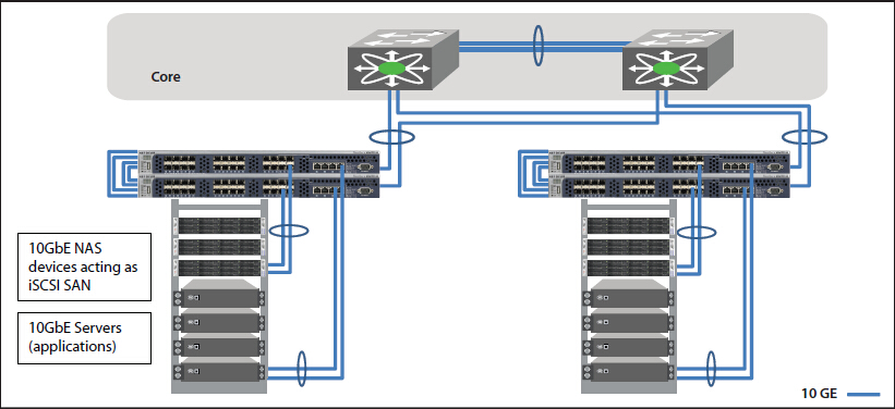
5G service providers also have to focus on the fiber optic network build of the data centers where the content is stored. At present, the transmission speed of data centers is evolving from 10G/25G, 40G/I00G to 25G/I00G, 200G/400G, which put forward new requirements for the multimode optical fibers used for interconnection inside the data centers. Multimode optical fibers need to compatible with the existing Ethernet standard, cover the future upgrades to higher speed like 400G and 800G, support multi-wavelength multiplexing technologies like SWDM and BiDi, and also need to provide excellent bending resistance to adjust to dense data centers cabling scenarios.

5g optical fiber cables.jpg

Figure 1: OM5 fiber in 100G BiDi and 100G SWDM applications

Under such conditions, the new broadband OM5 multimode fiber becomes the hotspot option for data center constructions. OM5 fiber allows multiple wavelengths to be transmitted simultaneously in the vicinity of 850 nm to 950 nm. By adopting the PAM4 modulation and WDM technology, OM5 optical fiber is able to support 150 meters in 100Gb/s, 200Gb/s, and 400Gb/s transmission systems, and ensure the ability of future short-distance and high-speed transmission networks, making it the optimal choice for intra-data center connections under the 5G environment.

Fiber TypeEffective Bandwidth (MHz.km)Full injection Bandwidth (MHz.km)
Fiber Type850nm953nm850nm953nm1310nm
OM3>2000/>1500/>500
OM4>4700/>3500/>500
OM5>4700/>35001850>500

Here is a comparison of the link length of OM5 and other multimode fiber over 850nm wavelength.

Link Length (M) @850nm wavelength
Fiber Type10GBASE-SR25GBASE-SR40GBASE-SR4100GBASE-SR4400GBASE-SR16400GBASE-SR8400GBASE-SR4.2
OM330070100701007070
OM4550100150100150100100
OM5550100150100150100150

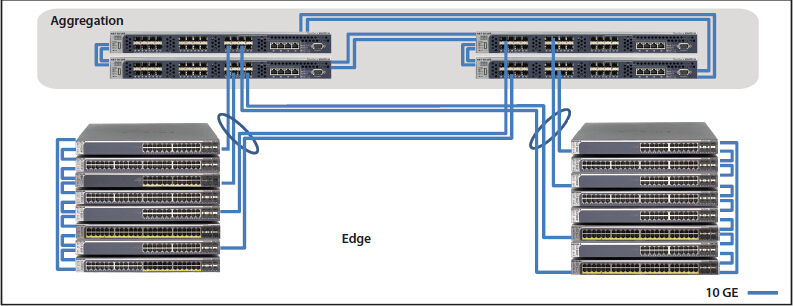
3. Micron Diameter Optical Fibers Enable Higher Fiber Density

Due to the complex deployment environments of the access layer or aggregation layer of 5G bearer networks, it’s easy to encounter problems like the limited existing cable pipeline resources. To ensure the limited space can hold more optical fibers, cable manufacturers are working hard to reduce the size and diameter of cable bundles. For example, recently the Prysmian Group has introduced the BendBright XS 180µm single-mode fiber to meet the 5G technology demands. This innovative optical fiber enables cable designers to offer strongly reduced cable dimensions while still keeping the 125µm glass diameter.

5G fiber cable.jpg

Figure 2: Prysmian’s BendBright XS 180µm fiber

Similarly, with the same principles, Corning has introduced the SMF-28 Ultra 200 fiber that allows fiber cable manufacturers to shave 45 microns off previous cable coating thicknesses, going from 245 microns down to 200 microns, to achieve a smaller overall outer diameter. And YOFC, another optical fiber manufacturer, also provides EasyBand plus-Mini 200μm reduced diameter bending insensitive fiber for 5G networks, which can reduce the cable diameter by 50% and significantly increase the fiber density in pipelines when compared with common optical fibers.

4. ULL Fiber with Large Effective Area Can Extend 5G Link Length

5G fiber manufacturers are actively exploring ultra low-loss (ULL) optical fiber technologies to extend the fiber reach as long as possible. The G.654.E optical fiber is such a type of innovative 5G fiber. Different from the common G.652.D fiber often used in 10G, 25G, and 100G, the G.652.E fiber comes with a larger effective area and ultra-low loss features, which can significantly reduce the nonlinear effect of optical fiber and improve the OSNR that are easily affected by higher signal modulation format in 200G and 400G connections.

Speed (bps)40G100G400G400G
Fiber Typecommon G.652low-loss G.652low-loss G.652innovative G.654.E
Maximum Capacity (Tbs)3.282020
Limit Relay Distance (km)60003200<800<2000
Typical Link Attenuation (dB/km)0.210.200.200.18
Fiber Effective Area (µm²)808080130

With the continuous increase of the transmission speed and capacity of the 5G core network and the clouded data center, fiber optic cables like this will be needed more. It’s said that the latest Corning’s TXF fiber, a type of G.654.E fiber, comes with high-data-rate capabilities and exceptional reach, able to help network operators deal with growing bandwidth demands while lowering their overall network costs. Recently, Infinera and Corning have achieved 800G across 800km using this TXF fiber, which shows this fiber is expected to offer excellent long-haul transmission solutions for 5G network deployment.

5. Optical Fiber Cable for Faster 5G Network Installation

5G network deployment covers both indoor and outdoor scenarios, the installation speed is a factor needed to consider. Full-dry optical cable using dry water-blocking technology is able to improve fiber splicing speed during cable installation. Air-blown micro cables are compact and lightweight and contain high fiber density to maximize the fiber count. This type of cable is easy to be installed in longer ducts with multiple bends and undulations, and it can save in manpower & installation time and improved installation efficiency via the blowing installation methods. For the outdoor fiber cable deployment, some anti-rodent and anti-bird optical cables also need to be used.

Get Ready for 5G Networks

Currently, optical fiber is the optimal medium capable of scaling to the 5G demands. 5G networks’ enhanced bandwidth capacity, lower latency requirements and complicated outdoor deployments bring challenges as well as unlimited possibilities for optical fiber manufacturers, but our optical networks must quickly adapt to meet such new demands. Except for the optical fiber mentioned above, it remains to be seen if the 5G fiber manufacturers will put forward other innovative fiber for the market as quickly as possible.

Article source: 5 Types of Optical Fibers for 5G Networks

Related Articles:

Challenges and Opportunities of 5G at the Time of COVID-19

CPRI vs eCPRI: What Are Their Differences and Meanings to 5G?

How to Choose a Suitable Network Switch?

A network switch is a small hardware device that centralizes communications among multiple connected devices within one local area network (LAN). Network switches come in different sizes, features and functions, so choosing a switch to match a particular network sometimes constitutes a daunting task. This blog will give you a few useful things to consider when choosing the appropriate switch for a layer in a particular network.

network switch

Network Switch Technology

While switching capabilities exist for several kinds of networks, including Ethernet, Fibre Channel, RapidIO, ATM, ITU-T G.hn and 802.11, network switch can operate at one or more layers of the OSI model. Switches provide multiple advantages in network designs. All switches provide the basic traffic filtering functions, which improves network bandwidth. Besides, the internal switching circuits allow traffic flows to simultaneously occur between multiple ports. Currently, mainstream network switches support Gigabit Ethernet speeds per switch port, but high-performance switches in data centers generally support 10 Gbps per link. Different models of network switches support varying numbers of connected devices. Home network switches provide 4/8 connection for Ethernet devices, while SMB switches typically support between 32 and 128 connections.

Considerations for Choosing the Suitable Network Switch

Careful planning before purchasing a switch will save you money. At the same time, it can help you ensure the equipment has the functionality that you organization is needed, or the switches can expand their capabilities as your requirements change and grow. Here are some suggestions you can use to help guide your switch purchase.

Connection Requirements

Connection requirements are a good place to start, since they usually dictate what types of switches will be needed, and they can affect pricing dramatically. Here are something you need to consider in advance:

1. Consider the number of users that your network will have to support

2. Consider your basic network infrastructure

3. Determine the network needs of the users (Fast Ethernet or Gigabit Ethernet)

4. Choose the role of the switch (core switch, distribution switch, access switch)

5. Pick a vendor and/or company (for example: Cisco, Juniper, HP, Dell, Arista, Brocade, FS.COM)

Number of ports

The number of users and the basic network infrastructure determine the number of ports. Common numbers of ports on network switches are 5, 8, 10, 24, and 48 ports. If you only have 5 or 6 users, then a small 8 port switch will probably be enough for your needs. Number of ports is one of the biggest factors in the cost of a switch, so if you buy a switch that only supports the number of users that you will have, you will likely save a fair amount of money.

FS network switch

Port Speeds and Types

Fixed switches come in Fast Ethernet and Gigabit Ethernet. Fast Ethernet allows up to 100 Mb/s of traffic per switch port while Gigabit Ethernet allows up to 1000 Mb/s of traffic per switch port. These ports may be a combination of SFP/SFP+ slots for fiber connectivity, but more commonly they are copper ports with RJ-45 connectors on the front, allowing for distances up to 100 meters. With Fiber SFP modules, you can go distances up to 40 kilometers. Currently, Gigabit Ethernet is the most popular interface speed though Fast Ethernet is still widely used, especially in price-sensitive environments.

Link Aggregation

If you have a 24-port switch, with all its ports capable of running at gigabit speeds, you could generate up to 24 Gb/s of network traffic. If the switch is connected to the rest of the network by a single network cable, it can only forward 1 Gb/s of the data to the rest of that network. Due to the contention for bandwidth, the data would forward more slowly. That results in 1 out of 24 wire speed available to each of the 24 devices connected to the switch. Therefore, the more ports you have on a switch to support bandwidth aggregation, the more speed you have on your network traffic.

Performance

Core Layer Switches: These types of switches are routed at the core layer of a topology, which is the high-speed backbone of the network and requires switches that can handle very high forwarding rates. The switch that operates in this area also needs to support link aggregation to ensure adequate bandwidth coming into the core from the distribution layer switches. Because of the high workload carried by core layer switches, they tend to operate hotter than access or distribution layer switches. Virtually, core layer switches have the ability to swap cooling fans without having to turn the switch off.

Distribution Layer Switches: Distribution layer switches plays a very important role on the network. They collect the data from all the access layer switches and forward it to the core layer switches. Distribution layer switches provides advanced security policies that can be applied to network traffic using Access Control Lists (ACL). This type of security allows the switch to prevent certain types of traffic and permit others.

Access Layer Switches: Access layer switches facilitate the connection of end node devices to the network. For this reason, they need to support features such as port security, VLANs, Fast Ethernet/Gigabit Ethernet, Power over Internet, and link aggregation. Port security allows the switch to decide how many or what type of devices are permitted to connect to the switch.

The Three-Layered Hierarchical Model

Power requirements

At any layer, a modern switch may implement power over Ethernet (PoE), which avoids the need for attached devices, such as a VoIP phone or wireless access point, to have a separate power supply. Since switches can have redundant power circuits connected to uninterruptible power supplies, the connected device can continue operating even when regular office power fails. Another characteristic you consider when choosing a switch is PoE. This is the ability of the switch to deliver power to a device over the existing Ethernet cabling. To find the switch that is right for you, all you need to do is choose a switch according to your power needs. When connecting to desktops which do not require PoE switches, the non-PoE switches are a more cost-effective option.

Future Growth: Stackable VS. Standalone

As the network grows, you will need more switches to provide network connectivity to the growing number of devices in the network. When using standalone switches, each switch is managed, troubleshot, and configured as an individual entity. In contrast, stackable switches provide a way to simplify and increase the availability of the network. With a true stackable switch, you can connect the stack members in a ring. If a port or cable fails, the stack will automatically route around that failure, many times at microsecond speeds. You can also add or subtract stack members and have it automatically recognized and added into the stack.

Conclusion

As you can see, there is a multitude of network switch options to choose from. So, have a close look at your current deployment and future needs to determine the right switch for your network. FS.COM is one of the network switch vendors, if you have any demand, welcome to visit our website.

How to Achieve a Reliable, Affordable and Simple 10 Gigabit Ethernet Deployment?

10 Gigabit Ethernet, or 10GE and 10GbE, is a group of computer networking technologies for transmitting Ethernet frames at a rate of 10 gigabits per second. Nowadays, 10 Gigabit Ethernet is gaining broader deployments by the increasing bandwidth requirements and the growth of enterprise applications. But there is a question to be considered when deploying 10 Gigabit Ethernet — how to achieve a reliable, affordable and simple 10 Gigabit Ethernet deployment? The text below will tell the answer.

10 Gigabit Ethernet and the Server Edge: Better Efficiency

Server virtualization supports several applications and operating systems on a single server by defining multiple virtual machines on the server. Virtual machines grow and require larger amounts of storage than one physical server can provide. Storage area networks (SANs) or network attached storage (NAS) provide additional and dedicated storage for virtual machines. But connectivity between the servers and storage must be fast to avoid bottlenecks. 10 Gigabit Ethernet is able to provide fastest interconnectivity for virtualized environments.

10 Gigabit Ethernet SAN versus Fibre Channel: Simpler and More Cost-effective

The Internet Small Computer System Interface (iSCSI), an extension of SCSI protocol used for block transfers in most storage devices and Fibre Channel, is making 10 Gigabit Ethernet an attractive, alternative interconnect fabric for SAN applications. The iSCSI capabilities allow 10 Gigabit Ethernet to compare very favorably to Fibre Channel as a SAN interconnect fabric. 10GbE networking can reduce equipment and management costs as its components are less expensive than highly specialized Fibre Channel components and do not require a specialized skill set for installation and management.

10 Gigabit Ethernet and the Aggregation Layer: Reduce Bottlenecks

10 Gigabit Ethernet allows the aggregation layer to scale to meet the increasing demands of users and applications. It can help bring oversubscription ratios back in line with network-design best practices, and provides some important advantages over aggregating multiple Gigabit Ethernet link, such as less fiber usage, greater support for large streams and longer deployment lifetimes.

10 Gigabit Ethernet and Fiber Cabling Choices

For any fiber cable deployment, the types of fiber cable, 10 Gigabit Ethernet physical interface and optics module form factor need to be considered. Form factor options are interoperable as long as the 10 Gigabit Ethernet physical interface type is the same on both ends of the fiber link.

10 Gigabit Ethernet and Copper Cabling Choices

Currently, three different copper cabling technologies for 10 Gigabit Ethernet are available. 10GBASE-CX4 was the first 10 Gigabit Ethernet copper standard. CX4 was relatively economical and allowed for very low latency. Its disadvantage was a too-large form factor for high density port counts in aggregation switches. SFP+ direct attach cables (DAC) connect directly into an SFP+ housing. It has become the connectivity of choice for servers and storage devices in a rack due to its low latency, small form factor and reasonable cost. 10GBASE-T is able to run 10 Gigabit Ethernet over CAT6a and CAT7 copper cabling up to 100 meters, but it needs technology improvements to lower its cost, power consumption and latency.

10 Gigabit Ethernet and the SFP+ Makeover: Direct Attach Cables are convenient for Short Runs

SFP+ direct attach cables integrate SFP+ connectors with a copper cable into a low-latency, energy-efficient, and low-cost solution. Direct attach cables are currently the best cabling option for short 10 Gigabit Ethernet connections.

10 Gigabit Ethernet and Link Aggregation Offers Redundancy and Resiliency

The Link Aggregation Control Protocol (LACP) standard defines a way of bundling several physical ports over one logical channel. From a deployment standpoint, it is far easier to implement a distributed LACP solution with stackable switches that allow link aggregation across the stack. In this configuration, the stack acts as a single logical switch and link aggregation is seamless.

10 Gigabit Ethernet and Top-of-Rack Best Practice

The diagram below shows a stackable 10 Gigabit Ethernet ToR switching solution enabling cost-effective SAN connectivity for servers and network storage. In addition to better performance, LACP functionality provides better availability and redundancy for servers and storage. Moreover, it provides failover protection if one physical link goes down, while iSCSI traffic load balancing ensures greater transmission throughput with lower latency.

10GbE ToR switching solution

10 Gigabit Ethernet and Distribution Layer Best Practice

The diagram below shows Gigabit access switches with 10 Gigabit uplinks and stackable 10 Gigabit aggregation switches. At the edge, stacks of access switches are virtualized into a single switch, reducing configuration and management overhead.

Gigabit access switches

To achieve a reliable, affordable and simple 10 Gigabit Ethernet deployment, the factors stated above need to be considered. Fiberstore SFP+ transceivers and SFP+ direct attach cables are ideal for cost-sensitive organizations considering 10 Gigabit Ethernet applications and they help growing companies support rising bandwidth requirements, new applications, and the demands of a fast-paced business environment.

Fiber Optic Access Network Will Be The Main Force Of Internet Information Highway In The Future

As with the rapid development of social information, fiber optic technology and devices which are dedicated to provide transfer of a new business for WAN and fiber optic access network. Developments of MSTP and PON are the most representative. They are also the best solution to provide various new business in the MAN and fiber optic access network which are based on fiber optic transmission technology. As water to the fish, the developments of fiber optic access technology can not without the support and development of fiber optic access devices.

Due to the constantly updated fiber optic access technology and more and more manufacturers’ accession, nowadays the fiber optic access devices categories are more and more obvious, mainly divided into three categories:

  • Fiber optic connection elements, it is applied into telecommunications and computer network terminal connections, related product: Fiber optic patch cable, fiber optic connector and so on.
  • Fiber optic transceiver, it is utilized for computer network data transmission, related products: Fiber optic splitter, fiber patch panels and so on.
  • Fiber optic engineer devices and fiber optic testers, it is specially for large-scale project, related products: Fiber optic fusion splicer, fiber optic testers.

Next we will introduce these three fiber optic access devices with a representative products respectively, they are fiber patch cables, fiber optic splitter, fiber optic fusion splicer.

Fiber optic patch cable (shown as the figure)is fiber optic cable or fiber optical unit which without fiber optic connector, it is used in fiber distribution frames on various link roads. Fiber patch cables are also used in long distance local optical network, data transmission and private network, various testing and control system.

Fiber optic splitter (shown as the figure), someone calls it as fiber coupler, it belongs to optical passive components, it is used in the telecommunications networks, fiber cable television networks, subscriber loop system. Fiber optic splitters can be divided into standard coupler (double branch, unit 1 x 2, that is, the light signal into two power, for example, 1×2 fiber optic splitter, 1 x4 fiber optic splitter, 1 x 8 fiber optic splitter and so on), star/tree fiber splitters and wavelength division multiplexer (WDM, if the wavelength is a high-density separation and wavelength spacing is narrow, it belongs DWDM).

Fiber optic fusion splicer(shown as the figure) is mainly used in telecommunication for fiber optic cables construction and maintenance, it is applied into telecommunication operators, engineering companies, private network, also used in the production of optical passive and active devices and fiber optical modules for fiber splicing.

All above the fiber optic access devices highly improve the data transmission and processing capabilities of fiber optic access network, and at the same time they can bring two advantages:

First, it solved the long distance transmission problems of fiber line attachment,and made its coverage range more widely. In this way, then it can reduce the number of transit nodes through whole the coverage network, make the structure of the network easier.

Second, it satisfied people’s needs to various broadband business, and improve the quality of new business data. It solved the problem of traditional copper cable access network fundamentally and laid a good foundation for achieving the dream of FTTH. I believe that in the future, fiber optic access network will be the main force of internet information highway.

Introduction of the Transients in Optical WDM Networks

A systems analysis continues to be completed to consider dynamical transient effects in the physical layer of an Optical WDM Network. The physical layer dynamics include effects on different time scales. Dynamics from the transmission signal impulses possess a scale of picoseconds. The timing recovery loops in the receivers be employed in the nanoseconds time scale. Optical packet switching in the future networks will have microsecond time scale. Growth and development of such optical networks is yet continuing. Most of the advanced development work in optical WDM networks is presently focused on circuit switching networks, where lightpath change events (for example wavelength add/drop or cross-connect configuration changes) happen on the time scale of seconds.

It is focused on the dynamics from the average transmission power associated with the gain dynamics in Optical Line Amplifiers (OLA). These dynamics may be triggered by the circuit switching events and have millisecond time scale primarily defined by the Amplified Spontaneous Emission (ASE) kinetics in Erbium-Doped Fiber Amplifiers (EDFAs). The transmission power dynamics will also be influenced by other active components of optical network, for example automatically tunable Optical Attenuators, spectral power equalizers, or other light processing components. When it comes to these dynamics, a typical power of the lightpath transmission signal is recognized as. High bandwidth modulation from the signal, which actually consists of separate information carrying pulses, is mostly ignored.

14-nodes Ring WDM
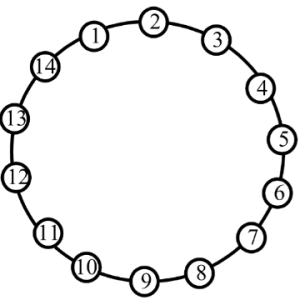
Ring WDM networks implementing communication between two fixed points are very well established technology, in particular, for carrying SONET over the WDM. Such simple networks with fixed WDM lighpaths happen to be analyzed in many detail. Fairly detailed first principle models for transmission power dynamics exist for such networks. These models are implemented in industrial software allowing engineering design calculations and dynamical simulation of these networks. Such models could possibly have very high fidelity, but their setup, tuning (model parameter identification) and exhaustive simulations covering a variety of transmission regimes are potentially very labor intensive. Adding description of new network components to such model could need a major effort.


14-nodes Mesh WDMThe problems with detailed first principle models is going to be greatly exacerbated for future Mesh WDM networks. The near future core optical networks will be transparent to wavelength signals on a physical layer. In such network, each wavelength signal travels through the optical core between electronic IP routers around the optical network edge using the information contents unchanged. The signal power is attenuated in the passive network elements and boosted by the optical amplifiers. The lightpaths is going to be dynamically provisioned by Optical Cross-Connects (OXCs), routers, or switches independently on the underlying protocol for data transmission. Such network is basically a circuit switched network. It might experience complex transient processes of the average transmission power for every wavelength signal at the event of the lightpath add, drop, or re-routing. A mix of the signal propagation delay and channel cross-coupling might result in the transmission power disturbances propagating across the network in closed loops and causing stamina oscillations. Such oscillations were observed experimentally. Additionally, the transmission power and amplifier gain transients could be excited by changes in the average signal power because of the network traffic burstliness. If for some period of time the wavelength channel bandwidth is not fully utilized, this could result in a loss of the average power (average temporal density of the transmitted information pulses).

First circuit switched optical networks are already being designed and deployed. Fraxel treatments develops rapidly for metro area and long term networks. Engineering design of circuit switched networks is complicated because performance has to be guaranteed for all possible combinations of the lightpaths. Further, as such networks develop and grow, they potentially need to combine heterogenous equipment from a variety of vendors. A system integrator (e.g., Fiberstore) of such network might be different from subsystems or component manufacturer. This creates a necessity of developing adequate means of transmission power dynamics calculations which are suitable for the circuit switched network business. Ideally, these methods should be modular, independent on the network complexity, and use specifications on the component/subsystem level.

Fiberstore has technical approach to systems analysis that’s to linearize the nonlinear system around a fixed regime, describe the nonlinearity like a model uncertainty, and apply robust analysis that guarantees stability and gratifaction conditions within the presence of the uncertainty. For a user of the approach, there is no need to understand the derivation and system analysis technicalities. The obtained results are very simple and relate performance to basic specifications of the network components. These specifications are somewhat not the same as those widely used in the industry, but could be defined from simple experimentation using the components and subsystems. The obtained specification requirements may be used in growth and development of optical amplifiers, equalizers, optical attenuators, other transmission signal conditioning devices, OADMs, OXCs, and any other optical network devices and subsystems influencing the transmission power.

What is the Meaning of 100G Channels Networks to Service Providers

As the traffic demand continues growing, telecom network providers have planned introducing the newly developed coherent 100G transport software in their networks to satisfy the demand. History shows us that network service providers have made use of every stage of the new channel capacity available from equipment developers.

Fiberstore

Fiberstore

The figure below shows the timeline for increases in fiber link capacity operating provider’s networks. In early 1990s, a capacity of a few hundred Mbps per link and just on channel per strand of fiber inside a transport network was typical. As email was a new communication tool in the centre 1990s, the fiber capacity gradually increased to a couple Gbps, and this growth continued to deal with the demand that individuals needed to start accessing the web. Into the later 1990s, fiber capacity grew even larger with the deployment of 10 Gbps channels and WDM techniques to multiplex and amplify a small number of wavelengths (4-8) on a single fiber pair. In early 2000s, Internet usage became commonplace but networking kept pace using the introduction of DWDM techniques that could support 40, 80, or maybe more wavelengths allowing fiber capacities to be near Tbps. For MUX/DeMUX solutions with different DWDM wavelengths, please visit Fiberstore. This extensive fiber capacity increase helped the transport network support continually increasing user demands. In the late 2000s, the introduction of 40G channels gave the capability of the networks another boost. By 2010, video sharing on the web by applications such as YouTube along with other video when needed (VoD) services started to stress existing network capacity. The development of the fiber capacity to approximately 10 Tbps per fiber. This will address near term capacity requirements, but moving forward, cloud computing along with other bandwidth hungry applications will continue to consume network resources, and new optical techniques to increase channel capacity and optical link capacity is going to be introduced progressively.

Fiberstore

The coherent 100G PM-QPSK system selected by the industry is able to run at the same channel spacing (50 GHz) like a 10G commercial system does in existing networks, and so the 100G system can offer enough capacity for network service providers to support customer demands in the near term without a network overbuild. Using the new 100G system, service providers expect the cost per bit declines in the same rate as or perhaps a faster pace than the decline rate of serves prices service providers can charge their clients, so that providers are able to remain competitive.

Before telecom service providers introduce commercial coherent 100G software in their networks, normally a series of technology trials must be conducted in their existing networks to determine the performance of the new technology. The primary purpose of the technology trials would be to guarantee the 100G channel behaves well in existing fiber network infrastructures. Fiber routes within the field may have high transmission attenuation, high PMD values, multiple connections and splicing points, various fiber types, etc. While most lab experiments are conducted with fiber loop configurations, a linear configuration in field trials is much more preferred to mimic optical links in tangible networks. Field trials give network providers proper expectation for that performance of the systems, which will be installed in networks. Issues present in these trials may also be sent back somewhere developers for further product improvement. In a single field trial a 112 Gbps coherent channel transmitted over 1730 km deployed DWDM link in a service provider’s network, while using DWDM Multiplexer. A carrier suppressed RZ and differential PM-QPSK modulation format was utilized for the channel in the trial. The trial results show that the coherent 100G channel has the capacity to serve long term routes. The plug and play performance of the equipment and robustness to chromatic dispersion and PMD impairments was demonstrated in the trial. Co-propagating the 100G channel with adjacent 10 Gbps signals without touching the fiber infrastructure proved one viable migration road to next generation networks. It’s a requirement for service providers to maintain the networks scalable and cost-effective while increasing channel capacity and fiber ability to have next-gen multi-terabit networks.

In another field trial a real-time, single carrier, coherent 100G PM-QPSK upgrade of the existing 10G/40G terrestrial system was demonstrated inside a service provider’s network. The field experiment shows the performance of the 100G channel sufficient for error-free operation after FEC over installed 900 km and 1800 km fiber links. The experiment proves that flexible and seamless 100 Gps channel upgrades to existing 10G and 40G DWDM systems are possible and practical.

Yet another coherent 100G channel field trial was performed on dispersion shifted fiber (DSF) links. The trial involved eighty 127 Gbps channels propagating on a deployed fiber link. L-band specturn was used to avoid zero dispersion reason for specturn, differnet from using C-band for SMF or NZDSF for additional common cases. The 100G channels, with 50 GHz channel spacing, traveled over 458 km DSF successfully with L-band EDFA only. Sufficient Q-margins remained as left for the 80 channels following the 458 km transmission. This field trial demonstrated that a 10 Tbps calss capacity DWDM product is feasible underneath the condition of small local dispersion by deploying coherent detection and high overhead (20%) coding gain FEC. This trial represented the highest fiber capacity in the field at the time the trial was conducted.

The reason for introducing 100G channels into transport networks is to carry large IP data traffic across IP networks, therefore, an “end-to-end” transport trial, i.e. an entire data transport trial from data equipment to data equipment, using a coherent 100G channel transmission over a long distance, is particularly meaningful to service providers. One such field trial, which involved a worldwide network company, a data equipment developer, a transport equipment developer, and a client interface developer, continues to be reported. In this trial a 112 Gbps single carrier real-time coherent PM-QPSK channel from a transponder carried native IP packet traffic over 1520 km field deployed fiber, with 100GbE router cards and 100G CFP interfaces. This trial shows the feasibility of interoperability between multi-suppliers’ equipment for 100G transport. This field trial, which fully emulated an operating near-term deployment scenario, confirmed that all key components required for deployment of 100GbE technology are maturing at the time the trial was conducted (early 2010).

Fiberstore

The detailed configuration of the trial is shown in the figure. A 10GbE test set generates 10GbE traffic for Router 1 and also the test set can be used for analyzing packet throughput too. Another router (Router 2) is used to accept a GbE signal containing a video signal using a video encoder and to send the recording signal to some video display via a video decoder following the signal transverses the trial path. Router 2 connects to Router 1 with another 10GbE link, containing the video traffic. Router 1 routes both 10GbE data streams to one of the 100GbE cards and routes back the 10GbE data streams form the other 100GbE card towards the corresponding 10GbE ports. The 100G CFP interfaces are used to connect 100GbE cards and the 100G transponder. The transmitter port of the CFP in the first 100GbE card is connected to the receiver port of the CFP in the transponder and also the receiver port of the second 100GbE card is linked to yhe transmitter port from the CFP in the transponder. The receiver port from the CFP in the first 100GbE card and also the transmitter port of the CFP in the second 100GbE card are of a fiber jumper (fiber patch cable) to shut the loop. The CFP transponder sends the 112 Gbps signal towards the fiber route-equipped having a long haul DWDM system. Both directions of the inline amplifiers have been used for the trial to save on equipment needed.

With these successful 100G system field trials, telecom network providers and other network operators have been convinced that the only optical carrier PM-QPSK with coherent detections is easily the most promising 100G channel solutions, at least for the time being. Now commercial 100G systems are for sale to the customers of the equipment developers and the customers are likely to enjoy the ten times fiber capacity begin their networks.


The Application of 10G PON Technology

With the major carriers “Broadband speed”, “Light of Copper” project extensively, The future will be a multimedia broadband services, video on demand, interactive games as the main feature, high-bandwidth, integrated operators will be judged promoted by the merits of the standard broadband products.

Under the broadband Fiber Optic Products in the trend, PON technology has become the world’s attention to various telecom operators hot technology is one of the operators to implement “broadband speed”, “Light of Copper” engineering technology base. Wheter EPON, or GPON, which provides only for the uplink and downlink bandwidth of 1G or 2G, but with the current interactive network TV (IPTV), high definition television (HDTV), online games, video services and other large flow, a large broadband business development and popularization of the per-user bandwidth demand is expected to grow every three years, a trend of increasing magnitude, from the future operator of long-term trends, per-user bandwidth demand will be 50-100 Mbit/s between. This way, EPON and GPON are unable to meet the future needs of the development of broadband services, the existing PON port bandwidth, there will be a bottleneck. Therefore, ITU-T, FSAN, IEEE and other major standards organizations begin the next generation of PON technology research.

Similar to 1G PON Technology, 10G PON and 10G EPON technology is still divided into two camps 10G GPON. In IEEE 802.3av 10G EPON standards, maximizing follows the usual IEEE 802.3ah content, with good upward compatibility.

10G PON technical analysis

Recalling the history of PON technology can be found in each of the PON technology from birth to the end of the day have to go through large-scale commercial development of technical standards, the relevant chip and optical module development, test and production, the creation of experimental and commercial bureau 4 stages of deployment, which lasted five years or so, each one of which will go through several stages of development of the argument.

Standardization Advances

Standards are mature is the precondition of judging whether a technology have lead to condition. At this stage, including IEEE, ITU-T, FSAN and number of ongoing international standardization organizations 10G EPON and 10G GPON standards development work of two technologies. Overall, the 10G EPON technology start time earlier than 10G GPON, therefore, the current standardization process of 10G EPON slightly faster than 10G GPON.

a. 10G EPON

Technologies with 1G EPON, 10G EPON standards are mainly led by the IEEE to complete. IEEE organization at September 12, 2009 released the 10G EPON international standards 802.3av, this standard focuses on the physical layer 10G EPON technology research, followed the tradition of 1G EPON MPCP protocol, the 1G EPON downlink bandwidth increases to 10G at the same time, to ensure that the operator of the original investment is not compromised and 10G EPON smooth upgrade, IEEE 802.3av standard defines and 1G EPON ONU coexist in the same ODN network of 10G EPON ONU standard parameters.

Further, in IEEE 802.3av standard, the physical layer defines two parameters: one asymmetric model, which 10G rate downlink and 1G rate uplink; other is symmetrical pattern, i.e. uplink rate and downlink rate are both 10G. Asymmetric mode can be considered as a transitional form symmetrical patterns, in the early less demand for upstream bandwidth and cost sensitive applications, you can use an asymmetric form. With the development of business and technology progress, will be gradually transition to a symmetrical mode.

b. 10G GPON

According to ITU-T Study plans, NGPON will experience two standard phases: the first phase is the coexistence with GPON, GPON ODN heavy use of XG-PON, which in turn contains the uplink and downlink phase XG-PON1 asymmetric and symmetric XG-PON2 two kind of model; Second stage is completely new ODN’s NGA2. High concern Wavelength Division Multiplexing – Passive Optical Network (WDM-PON) technology areas belong to the second stage, it was adopted in a fiber access network using multiple wavelengths to achieve the expansion, but the burst mode CWDM, colorless ONU transceivers, tunable WDM devices and some difficult technology can not break, WDM-PON is still at the proof stage.

In the end of September 2009 meeting of the ITU-T SG 15 plenary session, Q2 Working Group officially launched the NG-PON standard text in the first stage, that overall demand for next-generation PON systems (G.987.1) and Physical Layer Specifications (G.987.2), and also developed in mid-2010, publishing transmission convergence layer (G.987.3) and management control interface (G.988) standards program.

Technical Parameters

Wheter IEEE 802.3av, or ITU-T G.987 protocol suite, all relevant technical parameters for 10G PON physical layer index, optical power budget to make a detailed definition. However, due to the two major standards organizations considered the starting point, the technical indicators are also some differences.

a. 10G EPON

There are four key points of 10G EPON technology:

1. Defines six 10G EPON optical power budget, in view of the asymmetric mode PRX10, PRX20 and PRX30 as well as for symmetric mode PR10, PR20 and PR30, these six kinds of optical power budget model is basically to meet the construction needs of the service provider network;

2. 10G EPON technology in achieving the 1G EPON conventional multi-point control protocol layer (MPCP) based on the forward compatibility, also extended the original message type, for reporting optical terminal equipment (OLT), ONU Fiber Optic Transceiver switch time to meet the 10G EPON system requirements;

3. 10G EPON uses (255, 223) Forward Error Correction (FEC) encoding method, the encoded with FEC coding for the same strain of 1G EPON, but its strong support 10G EPON coding gain can lower the sensitivity of the optical receiver;

4. 10G EPON uplink and downlink wavelength for the re-planning, downlink using 1268-1280nm wavelength, then reuse the original uplink of 1G EPON 1575-1580 nm wavelength, the wavelength in order to avoid conflicts, 10G EPON uplink only use time division multiple access (TDMA) manner.

b. 10G GPON

Has been released G.987.1 standard that defines 10G GPON system’s overall technical requirements and system architecture, clearly put forward the 10G GPON system to ensure good QoS, based on the traditional telecom services to fully support all emerging businesses and the same time, also provides dynamic Bandwidth Allocation (DBA) algorithm, energy saving, authentication and encryption related content to inherit the original 1G GPON technology; The G.987.2 is the focus of standardized 10G GPON physical layer parameters, including downlink rate, ODN power budget, splitting ratio, up and down the line wavelength range and line coding, etc., although down the line of 10G EPON same wavelength range and 10G EPON, GPON but due to the wavelength with 1G is not conflict, therefore, 10G GPON uplink and downlink are used wavelength division multiple access (WDMA) manner.

Industrial chain development

A complete industrial chain, including chip PON, optical modules and equipment three links. If to analysis PON industry chain, it need to start from the three links, analysis of every link current development status and future development trend.

Overall, 10G EPON and 10G GPON is currently not reach the requirements of large-scale commercial applications, although some equipment manufacturers have recently introduced a 10G EPON or 10G GPON products, and with operators, the creation of some experimental inning, but still in the laboratory testing phase, is still some distance away from the large-scale commercial.

Conclusion

10G PON technology to meet future access networks, “large-capacity, fewer offices,” the direction of development, while improving access speed, supports larger branching ratio, covering more users. Therefore, 10G PON technology will become the future telecom operators to achieve “broadband speed”, “Light of Copper” and other broadband network construction hot technology for sustainable development.

To Introduce Optical Communication and Internet Technology

Technology of Terabit Optic Circuit Packet Integrated Switching System

New exchange system and integrated optic circuit packet layers will be provided to meet the large capacity, high quality, low cost and effective demand so as to adapt to the cable wireless traffic spikes in the service in the future.

A connection-oriented packet transport technology is considered to be an effective way to improve the performance of packet data transmission. It is necessary, can put a layer of transport network in the direction of capital spending and minimizing operating costs to overcome the network provider’s storage and traffic increase of income. And unified control mechanism is applied to the network resource allocation, flexible wavelength circuit and packet layer according to the service characteristics. The key technologies of the system are as followings.

Technology of Terabit Optic-Circuit-Packet Integrated Switching System
  • Connection-oriented Packet Transport
  • Optic-Circuit-Packet Integrated Switch
  • Optic-Circuit-Packet Layer Integrated Control/Management
Technology of beyond-100G Optical Transmission
  • Long-reach OTN Transceiver
  • Short-reach Ethernet Transceiver

Technology of Terabit Optic-Circuit-Packet Integrated Switching System

Technology of terabit optic circuit packet integrated switching system

Smart IDC Network Control Technology for Cloud Service

Along with the rapid spreads and changes of cloud services and the technologic growth of the components in the IDC, the IDC networks are demanding following changes.

Cloud optimized: The virtualization rate of the server is rising up to 10:1-100:1 and storage virtualization is also possible recently. So IDC is requiring the cloud-optimized virtualization to the network side which are connecting the virtualized cloud resources.

Flattened: There are network control needs to reduce the delay latency of virtualized server-to-server communications which is occuping up to 70%, to rise the utilization rate the link resources of L2 IDC networks of Tree-shape multi-layer hierarchical architecture with STP.

Auto-Managed: There are demands of integrated management of network and cloud resources between IDC and create/delete/VM migration to ensure seamless services in the cloud.

Therefore, our research target to develop the Smart IDC fiber optic communication to solve the current problems of IDC network with the 3 IDC network control technologies of the Cloud-Optimized Virtual Network Control technology, the Flattened IDC Network Control Technology and Auto-managed IDC network control technology.

High Speed Optical Transmission Technology

The rapid progress in optical transmission technology has been supporting the ever increasing transmission traffic. In particular, the WDM technology, it is by the end of last century, played a main role. However, the new technology needs to use data traffic exponentially. A solution is 100Gb/s transmission. IEEE announced 40G/100G Ethernet standard and ITU-T has completed ONT standard to accommodate 100G signals in DWDM backbone network. Recently, the 100Gb/s transmission technology has become the commercial deployment, in addition to the existing 10Gb/s and 40Gb/s. Already technologies beyond 100G or 400G are started being discussed. With a long-term perspective, it is a disruptive technology, SDM (space division multiplexing) technology is seriously explored to harness the traffic in economic and energy efficient way.

High Speed Optical Transmission Technology

Next Generation WDM-PON Technology

The WDM-PON is promising technology to provide broadband access offering optic-wireless converged next generation multi-application service with the highest quality.

Advantages of the WDM-PON

* Using multiple wavelength on a single fiber, each of which carries a transmission bandwidth up to 10Gb/s at maximum; Therefore, the WDM-PON can reduce the optical access infrastructure;

* Suitable for long-reach application and possible to achieve OPEX reduction;

* Provide co-existence with legacy TDM-PON (EPON system, and GPON) systems and pay as you grow upgradability;

* Unique advantages of so-called protocol transparency, which means that it requires no specific transmission protocol, and the physical layer security, in addition to scalability in the increase of the bandwidth and guarantee of the quality of service based on bandwidth abundance.

Guide To Choose The Best Fiber Optic Cable Suits Your Application

Fiber optic cable is favored for today’s high-speed data communications because it eliminates the problems of twisted-pair cable, such as near-end crosstalk (NEXT), electromagnetic interference (EMI), and security breaches. Fibre Optic Cable is the preferred option in the interconnecting links between floors or buildings, is the backbone of any structured cabling solution. While, making the right decisions when it comes to Data Network cabling is difficult as it can make a huge difference in the ability of your network to reliably support current and future requirements. There are many factors to consider and today I will guide you through the many options available and find the best one suits your application.

1. Multimode Fiber Cable Or Single-mode Fiber Cable

There are two basic types of fiber: mulitimode and single-mode. Both types consist of two basic components: the core and the cladding which traps the light in the core.

Multimode fiber cable

Multimode fiber, as the name suggests, permits the signal to travel in multiple modes, or pathways, along the inside of the glass strand or core. It is available with fiber core diameters of 62.5 and a slightly smaller 50 microns. The problem with multimode fiber optics is that long cable runs in multiple paths may lead to signal distortion. This can result in incomplete and unclear data transmission.

Applications covering short distances can use multimode fiber optic network cable. Ideal uses for such kinds of cables are within data center connections. Multimode cables are economical choices for such applications. There are various performance levels within the multimode fiber optic cable such as OM3 cable for distances within 300 m, OM4 cable supports Gigabit Ethernet distances within 550m and 10G applications.

Single-mode fiber cable

Single-mode fiber cables offer a higher transmission rate. These cables contain a tiny core that measures about five to ten microns. These tiny cores have the capacity to eliminate distortion and produce the highest transmission speeds. Single-mode fiber generally has a core that is 8.3 microns in diameter. Singlemode fiber requires laser technology for sending and receiving data. Although a laser is used, light in a single-mode fiber also refracts off the fiber cladding. The presence of high intensity lasers helps transfer data across large distances. Singlemode has the ability to carry a signal for miles.

Single mode is used for long haul or extreme bandwidth applications, gives you a higher transmission rate and up to 50 times more distance than multimode, but it also costs more. The small core and its single lightwave virtually eliminate any distortion that could result from overlapping light pulses, providing the least signal attenuation and highest transmission speeds of any fiber cable type.

The best choice to choose multimode optical cable when the transmission distance is less than 2km. In the other sides, use single-mode optical cable when the transmission is more than 2km. Although the core sizes of multimode and singlemode fiber differ, after the cladding and another layer for durability are applied, both fiber types end up with an outer diameter of about 250 microns. This makes it both more robust and easier to work with.

2. Indoor Cable Or Outdoor Cable

The major difference between indoor and outdoor cables is water blocking. Any conduit is someday likely to get moisture in it. Outdoor cables are designed to protect the fibers from years of exposure to moisture.

Indoor Cables

Indoor cables are what we call “tight-buffered” cables, where the glass fiber has a primary coating and secondary buffer coatings that enlarge each fiber to 900 microns—about 1mm or 1/25-inch—to make the fiber easier to work with. Indoor cables are flexible, and tough, containing multiple Tight Buffered or Unit Cord fibers.

Types Of Indoor cables available

indoor cables

Simplex and Zip Cord: Simplex Fiber Optic Cables are one fiber, tight-buffered (coated with a 900 micron buffer over the primary buffer coating) with Kevlar (aramid fiber) strength members and jacketed for indoor use. The jacket is usually 3mm (1/8 in.) diameter. Zipcord is simply two of these joined with a thin web. It’s used mostly for patch cord and backplane applications, but zipcord can also be used for desktop connections. They are commonly used in patch cord and backplane applications. Additionally, they can be utilized for desktop connections. These cables only have one fiber and are generally used indoors.

Distribution cables: They contain several tight-buffered fibers bundled under the same jacket with Kevlar strength members and sometimes fiberglass rod reinforcement to stiffen the cable and prevent kinking. These cables are small in size, and used for short, dry conduit runs, riser and plenum applications. The fibers are double buffered and can be directly terminated, but because their fibers are not individually reinforced, these cables need to be broken out with a “breakout box” or terminated inside a patch panel or junction box. The distribution cable is smaller and used in dry and short conduit runs, plenum and riser applications, is the most popular cable for indoor use.

Breakout cables: They are made of several simplex cables bundled together inside a common jacket for convenience in pulling and ruggedness. This is a strong, rugged design, but is larger and more expensive than the distribution cables. It is suitable for conduit runs, riser and plenum applications, is ideal for industrial applications where ruggedness is important or in a location where only one or two pieces of equipment (such as local hubs) need to be connected.

Outdoor Cables

Optical fiber in outdoor applications requires more protection from water ingress, vermin, and other conditions encountered underground. Outdoor cables also need increased strength for greater pulling distances. Buyers should know the potential hazards that the cables will face, for example, if the cables will be exposed to chemicals or extreme temperatures.

Loose Tube cables: These cables are composed of several fibers together inside a small plastic tube, which are in turn wound around a central strength member and jacketed, providing a small, high fiber count cable. This type of cable is ideal for outside plant trunking applications, as it can be made with loose tubes filled with gel or water absorbent powder to prevent harm to the fibers from water. Since the fibers have only a thin buffer coating, they must be carefully handled and protected to prevent damage. It can be used in conduits, strung overhead or buried directly into the ground.

Ribbon Cable: This cable offers the highest packing density, since all the fibers are laid out in rows, typically of 12 fibers, and laid on top of each other. This way 144 fibers only has a cross section of about 1/4 inch or 6mm! Some cable designs use a “slotted core” with up to 6 of these 144 fiber ribbon assemblies for 864 fibers in one cable! Since it’s outside plant cable, it’s gel-filled for water blocking.

Armored Cable: Cable installed by direct burial in areas where rodents are a problem usually have metal armored between two jackets to prevent rodent penetration. This means the cable is conductive, so it must be grounded properly. You’d better choose armored fiber cable when use cable directly buried outdoor.

Aerial Cable: They can be lashed to a messenger or another cable (common in CATV) or have metal or aramid strength members to make them self supporting. Aerial cables are for outside installation on poles.

The table below summarizes the choices, applications and advantages of each.

Cable Type Application Advantages
Distribution Premises Small size for lots of fibers, inexpensive
Breakout Premises Rugged, easy to terminate, no hardware needed
Loose Tube Outside Plant Rugged, gel or dry water-blocking
Armored Outside Plant Prevents rodent damage
Ribbon Outside Plant Highest fiber count for small size

All cables share some common characteristics. For example, they all include various plastic coatings to protect the fiber, from the buffer coating on the fiber itself to the outside jacket. All also include some strength members for pulling the cable without harming the fibers. Outdoor fiber optic cable has moisture protection, either a gel filling or a dry powder or tape. Direct-buried cables may have a layer of metal armor to prevent damage from rodents. It is advisable that you should customize your cable to make it suitable to your application when the quantity of fiber optic cables is large and also for the cost-effective reasons. Knowing basic information about fiber optic cables make choosing the right one for the project a lot easier. It is always beneficial to konw more about fiber optic cables.

Fiber Optic Is The Trend In Networks Compared With Copper

Fiber optics is a hot trend in today’s world of communication network, which is a technology that uses glass (or plastic) threads (fibers) to transmit large amount of data. In recent years it has become apparent that fiber-optics are now replacing copper wires as the best means of communication signal transmission. They span the long distances more easily and provide backbones for many communication networks. Why fiber optic is gradually replacing copper networks, we first should konw the pros and cons of copper.

Pros and cons of copper

Telephone companies have long used copper lines, while the cable television companies have relied on coaxial cable for TV, Internet, and VoIP(Voice over Internet Phone) telephone service. Both industries now are making increased use of fiber, hybrid fiber-copper, or hybrid fiber-coaxial cable lines.

The benefit of the old copper service is that, unlike fiber and hybrid-fiber lines, it carries not only the voice and data signals but also the power to operate a standard, non-cordless telephone. The phone company itself provides that power, which often keeps the phones working even when a problem at the power company knocks out electric service.

But traditional copper telephone lines can’t handle the large amount of data required for television and high-speed Internet services, especially over long distances. Although advanced techniques can enhance copper’s capabilities and most other companies are installing fiber or hybrid fiber lines, in some cases alongside the copper ones. We’ve found that telephone and cable company terms and conditions typically warn customers that these systems can’t maintain phone service indefinitely during a power failure, if at all.

The problem is greatest with cable company VoIP services and with systems that use fiber lines all the way to the home. It can be less of a concern with hybrid copper-fiber systems, in which copper lines carry the signal the last mile or so to the home. In those systems, carriers can maintain phone power by installing batteries and generators at the point where the fiber meets the copper.

Why Use Fiber Optic? Is Copper Really Cheaper Than Fiber?

Telcos use fiber to connect all their central offices and long distance switches because it has thousands of times the bandwidth of copper wire and can carry signals hundreds of times further before needing a repeater. The CATV companies use fiber because it give them greater reliability and the opportunity to offer new services, like phone service and Internet connections. Both telcos and CATV operators use fiber for economic reasons, but their cost justification requires adopting new network architectures to take advantage of fiber’s strengths.

When it comes to the cost, fiber optic is always considered to be more expensive than copper cabling. Whatever you look at – cable, fiber termination kit or networking electronics – fiber costs more. So isn’t it obvious that Fiber Optic Network is more expensive than copper? Maybe not! Looking at the cabling component costs may be not a good way to analyze total network costs. A properly designed premises cabling network can also be less expensive.