Things You Should Know about Fiber Optic Connector Polishing

Optical fiber is utilized for high-speed and error-free data transmission across connector assemblies. So the connector end faces need to be polished to optimize performance. And also the connectors must follow acceptance criteria related to insertion and back reflection loss as well as end-face geometry specifications. This article will talk about the fiber optic connectors polishing.

Polishing Process

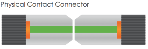
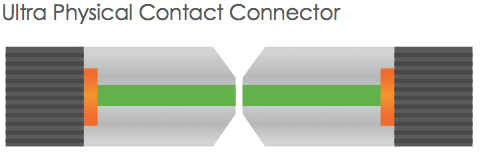
Early physical contact connectors required spherical forming of their flat end faces as part of the polishing procedure. It involved a four-step process: epoxy removal, ferrule forming, and preliminary and final polishing. These steps utilized aggressive materials for epoxy removal and ferrule forming, generally accomplished with diamond polishing films. Now the polishing process has developed into a sequence of epoxy removal, followed by rough, intermediate and final polishing cycles because almost all connectors are manufactured with a pre-radiused end face. One goal is to avoid excessive disruption of the spherical surface, while still producing a good mating surface.

Polishing Specifications

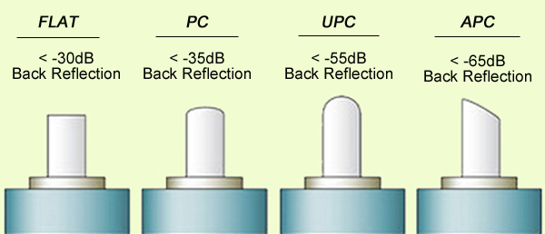
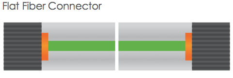
Polishing specifications for fiber connectors fall into two categories related to performance and end-face geometry. Back reflection and insertion loss specifications are the most critical measures of polished end functionality. The insertion loss is the amount of optical power lost at the interface between the connectors caused by fiber misalignment, separation between connections (the air gap) and the finish quality of each connector end. The current standard loss specification is less than 0.5 dB, but less than 0.3 dB is increasingly specified. Back reflection is the light reflected back through the fiber toward the source. High back reflection can translate to signal distortion and, therefore, bit errors in systems with high data transfer rates.

Polishing Material

Today several types of connectorized fibers are available, the most common of which are 2.5 mm, 1.25 mm and multifiber. Connector end faces must first be air-polished to ensure a proper mating surface. This will be followed by a sequence of polishing steps depending on the type of connector, the back reflection and the insertion loss specifications. Regardless of the connector type, most polishing sequences begin with aggressive materials, including silicon carbide to remove epoxy and diamond lapping films for beginning and intermediate polishing. These remove both surrounding material and fiber at the same rate. But the last polishing step needs a less aggressive material to attack only the fiber, such as silicon dioxide. Using a material for final polishing that is too aggressive could result in excessive undercut. The wrong final-polish material can cause excessive protrusion, leading to fiber chipping and cracking during the connector mating process.

Impact Factor

Issues to be examined include the polishing films used, the type of epoxy and lubrication. Films are the most significant impact because the gradations and quality vary from supplier to supplier. End users should pay attention on selecting film type. Excessively aggressive films can destroy a 125-μm fiber and the end-face radius. Epoxy removal is also essential to contamination-free polishing. Some types of epoxies can be removed more easily with specific grades of silicon-carbide polishing films. The films to use in this step depend on the size of the epoxy bead mounted on the connector end face and the epoxy type. Epoxies have different varieties. Some will be tacky, some firm. In all, a contamination-free environment is essential to optimizing connector polishing.

Polishing may be an old art form, but for the immediate future, it’s here to stay. Undoubtedly inspection criteria will increase. Polishing procedures will be driven to change, and new connector style will also make us continuously strive to reinvent our approach to polishing. Fiberstore has various products about fiber optic polishing. For more details, please visit FS.COM.

Evolution of Flat, PC, UPC and APC Fiber Connectors

When a connector is installed on the fiber end, loss will be incurred. Some light loss would be reflected back directly down the fiber towards the light source that generated it. These back reflections, or Optical Return Loss (ORL) will damage the laser light sources and also disrupt the transmitted signal. Fiber connectors with different polishing types have different back reflections (see the picture below). With the development of technology, four polishing types are available: flat-surface, Physical Contact (PC), Ultra Physical Contact (UPC), and Angled Physical Contact (APC). How one evolves into another? This article will tell the answer.

polishing type

Flat Fiber Connector

The original fiber connector is a flat-surface connection, or a flat fiber connector. The primary issue of it is that a small air gap between the two ferrules is naturally left when mated. This is partly because the relatively large end-face of the connector allows for numerous slight but significant imperfections to gather on the surface. The flat fiber connector is not suitable for single-mode fiber cables with a 9µm core size, thus it is essential to evolve into Physical Contact (PC) connectors.

flat fiber connector

PC Fiber Connector

The Physical Contact is polished with a slight spherical design to reduce the overall size of the end-face, which helps to decrease the air gap issue faced by Flat Fiber connectors. It results in lower Optical Return Loss (ORL) with less light being sent back towards the power source.

PC connector

UPC Fiber Connector

Building on the convex end-face attributes of the PC, but utilizing an extended polishing method creates an even finer fiber surface finish: Ultra Physical Contact (UPC) connector. It has a lower back reflection (ORL) than a standard PC connector and allows more reliable signals in digital TV, telephony and data systems. UPC fiber connector could be used with both single-mode fiber and multimode fiber. Usually the UPC single-mode fiber connector is blue, but the UPC multimode fiber connector is beige. (Note: 10G UPC multimode fiber connector is aqua.)

UPC connector

PC and UPC connectors do have a low insertion loss, but the back reflection (ORL) depends on the the surface finish of the fiber. The finer the fiber grain structure, the lower the back reflection. When PC and UPC connectors are continually mated and unmated, the back reflection will begin to degrade. So there is a need for a connector with low back reflection and it could sustain repeated matings/unmatings without ORL degradation.

APC Fiber Connector

The end faces of Angled Physical Contact connectors are still curved but are angled at an industry standard eight degrees, which allows for even tighter connections and smaller end-face radii. Combined with that, any light that is redirected back towards the source is actually reflected out into the fiber cladding, again by the virtue of the 8°angled end-face. APC connector back reflection does not degrade with repeated matings/unmatings. APC fiber connector can only be used with single-mode fiber and it is green.

APC connector

It is clear that all of the connector end-face options mentioned above take a place in the market. And it is hard to claim that one connector beats the others when your specification needs to consider cost and simplicity not just optical performance. Your particular need decides which one to choose. For those applications calling for high precision optical fiber signaling, APC should be the first consideration, but less sensitive digital systems will perform equally well using UPC. For various connector options, please visit FS.COM.

Related Article: Differences between CWDM and DWDM
How Many Fiber Connector Type Do You Know?

Guide To Fiber Optic Polishing

Optical fibers require end-surface treatment for proper light propagation and that includes polishing their ends. Polishing is essential for almost all glass-based fibers with cladding diameters larger than 200 microns. Furthermore, all fiber connectors require polishing. The process of fiber optic polishing can occur in the field or in a technical lab, it employs a range of tools and products used to create precision fits and finishes in the delicate glass ends.

There is typical fiber polishing machine for fiber optic polishing. Fiber Optic Polishing Machines are used to polish the end faces of fiber optic products (cables, connectors, adapters, etc.) in order to minimize signal losses due to scattering. Polishing machines can increase productivity by providing rapid polishing of many different connector styles.

When selecting a fiber polishing machine, there are several features to consider, including adjustable pressure, changeable holders, a timer, and the ability to request custom specifications. Most polishing machines do not offer the flexibility of speed adjustment. This is partially due to the fact that most users only need to handle one type of ferrule material such as zirconia. A slight speed variation does not have significant impact on connector polish result. However, a versatile polisher should have the capability to change speed according the ferrule and polishing film material.

The polishing job typically involves fiber optic fusion splicer, among other cable crimping tools and connectors are needed. It also requires 99% isopropyl alcohol, polishing (lapping) film and pad, a polishing puck, and epoxy or adhesive. Some technicians also find needle, syringe, and piano wire useful.

Several Different Polish Options On Fiber Connectors

The different polish of the fiber optic connector ferrules result in different performance of them, mainly on the back reflection (return loss). Generally, PC type is required at least 40dB return loss or higher, UPC is 50dB or higher, APC is 60dB or higher. (As we know, the higher the return loss, the better the performance). Insertion loss of them all should be less than at least 0.3dB, the lower the insertion loss the better the performance.

Things You Need To Mind During Fiber Optic Polishing

It is important not to dwell on any polishing film longer than necessary. Too much polishing can result in undesirable ferrule length, unnecessary polish film wear, and degraded polish finish due to particle accumulation. Make proper adjustments to the recommended polishing time in each step in case they are less than ideal.

Eye protection is always necessary to protect against powerful industrial lasers used in long-distance single-mode networks. Supporting tools may include a visual fault locater to troubleshoot fiber faults and breaks. A fiber-optic inspection microscope permits precision analysis of hair-fine fibers. Additionally, technicians rely upon jacket strippers, cutters, cable slitters, and fusion splicers.

Conclusion

Fiber polishing is a science but much like an art. The science of polishing is crystallized in a well designed machine while the art of polishing reside in the procedure and the continuous effort for improvement by the individual user. The procedure and the training are just as valuable as the polishing machine.