Examples of CWDM Network Deployment Solution

Based on the same concept of using multiple wavelengths of light on a single fiber, CWDM and DWDM are two important technologies in fiber optical communications. As we all know, although the transmission distance of CWDM network is shorter than that of DWDM, it costs less and has the scalability to grow fiber capacity as needed. This article intends to give a simple introduction of components in CWDM networks and to explore some examples of CWDM network deployment cases.

Common Components Used in CWDM Networks
CWDM Mux/Demux

CWDM Mux/Demux, which is based on the film filter technology, is the basic component in CWDM networks. It can combine up to 4, 8 or 16 different wavelength signals from different fiber extenders to a single optical fiber, or it can separate the same wavelengths coming from a single CWDM source. That’s why CWDM can extend existing fiber capacity.

CWDM OADM (Optical Add-Drop Multiplexer)

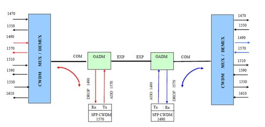
A CWDM OADM is a device that can add (multiplex) and drop (demultiplex) channels on both directions in a CWDM network. It can add new access points anywhere in CWDM systems without impacting the remaining channels traversing the network. With this ability of OADM, the access points can be added to liner, bus, and ring networks, where the dual direction ring design provides redundant protected architecture.

CWDM Optical Transceiver

Optical transceiver is a necessary element in optical networks. And CWDM optical transceiver is a type of module supporting CWDM network application with CWDM wavelengths. When connected with CWDM Mux/Demux, CWDM transceiver can increase network capacity by allowing different data channels to use separate optical wavelengths (1270nm to 1610nm) on the same fiber. And the common CWDM transceiver type is SFP, SFP+, XFP, XENPAK, X2, etc.

CWDM Network Deployment Solution
Example One

Description: there are five buildings (Sheriff, Courthouse, Admin, Police & Fire, & Public Works) connected via multimode fiber cables (MMF) or single mode fiber cables (SMF). These buildings are linked via multimode SFPs in an existing D-link switches to create one network for internal use of the city offices. Below is a simple graph to show the situation.

CWDM Network 1

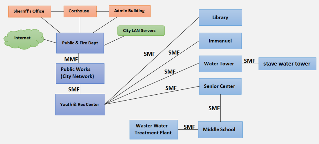
Requirements: the goal is to install a single mode fiber network in town to connect numerous buildings. Some of these buildings have access to the city LAN. The Public Works building need to connect with Youth & Recreation Center, Library, Immanuel Lutheran School and the Senior Center. And all these buildings should have unfiltered Internet. Besides, the Waster Water Treatment Plant should be connected passing through the Senior Center. All these services are achieved using CWDM technology.

Solution: according to the requirements, this is a CWDM networks with several buildings to connect with. Here is the solution diagram.

CWDM Network

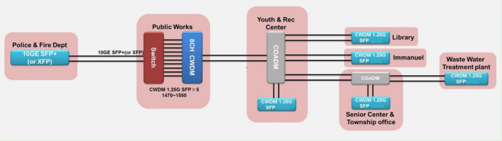
In the diagram above, we can see there is an 8CH CWDM Mux/Demux connected with the switches. According to the requirements, Youth & Recreation Center, Library, Immanuel Lutheran School and Senior Citizen Center should be connected with the Public Works and need unfiltered services. Therefore, a 4CH CWDM OADM is placed after the CWDM Mux/Demux. Then the four wavelengths will be drop and into the four buildings. In addition, another CWDM OADM is deployed in Senior center to connect the Waster Water Treatment Plant, to meet the requirement. And each site also needs to use CWDM optical transceivers.

Example Two

Description: on site A, there are three Ethernet switches and a T3 router. And their working wavelengths 1470nm, 1490nm, 1510nm, 1530nm and 1610nm. Other three sites B, C, and D also have three Ethernet switches. And a T3 router is in site E. As the following figure shows.

CWDM OADM

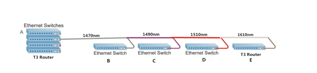
Requirements: Considering the cost, all the wavelengths should be transmitted on a single fiber using CWDM technology.

Solution: according to the requirements, here is a simple diagram showing the solution.

CWDM Mux Demux

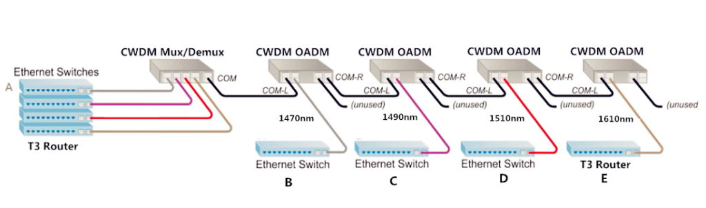
In order to save cost, a 4CH CWDM Mux/Demux is used to multiplex four wavelengths (from three switches and one router) into one single fiber. At the first site B, a 1CH CWDM OADM is installed to remove one wavelength which is associated with network B. And other three sites are the same—dropping one wavelength associated with corresponding switch or router.

Summary

This article mainly introduces two CWDM network deployment examples. All the components like the CWDM Mux/Demux, CWDM OADM and CWDM transceiver are available in FS.COM. If you are interested in them, please contact us via sales@fs.com.

Related article:Differences between CWDM and DWDM

Optical Add-drop Multiplexer Overview

With an explosive growth in the amount of information transmission, the optical telecommunication networks develop rapidly. The progress of single wavelength point-to-point transmission lines to wavelength division multiplexed optical networks has introduced a demand for wavelength selective optical add-drop multiplexer (OADM) to separate or route different wavelength channels. This paper will have an overview of the OADM.

OADM Technology

The introduction of optical add drop multiplexers into optical networks allows traffic to be inserted, removed and, most importantly, bypassed. Moreover, OADM can support functions such as protection, drop/continue, loop-back and wavelength reuse of the optical channels. Drop and continue refer that the channel is removed at the node but allowed to pass through to the next OADM. Wavelength reuse means the dropped channel does not pass through to the next OADM, instead, a new channel of the same wavelength can be added. Below figure explains OADMs work in a CWDM system.

CWDM OADM
Passive and Dynamic OADM

OADM can be used in the dynamic as well as static mode. The add and drop wavelengths are fixed in the passive OADM, while in dynamic mode, the OADM can be set to any wavelength after installation. Passive OADM is mainly used in networks with WDM systems (CWDM and DWDM) or hubbed structures, where the OADM is connected to a central hub, e.g. in the metropolitan network. In order to utilize resources in a more efficient way, the OADM with dynamic wavelength assignment are preferred when traffic variations are comparable to network capacity. It can select any wavelength by provisioning on demand without changing its physical configuration.

Advantages

OADM has many advantages. The most striking one is that its multiplexing happens to coincide with the minimum loss area of single mode fiber. This reduces the transmission loss of the light signal which can be transmitted relatively far distance. Additionally, it is transparent to digital signal format and data rate. Its gain saturation recovery time is long, and has a very small crosstalk between the respective channels. What’s more, multiple channels of information carried over the same fiber with each using an individual wavelength. Narrow channel spacing or wavelength selection give rise to denser channels in the same wavelength range. Last but not the least, repeater or amplification sites are reduced, which results in large savings of funding.

Applications

OADM supports standard network topologies such as point-to-point and ring. It can be used at different points along the optical link to insert/remove or route selected channels increasing the network flexibility. This feature is particularly important in metropolitan WDM lightwave services where offices or sites can be connected by different add-drop channels, for instance in an interoffice ring. In WDM systems, OADM is installed in a multi-wavelength fiber span, and allows a specific wavelength on the fiber to be demultiplexed (dropped) and remultiplexed (added) while enabling all other wavelengths to pass. Then it can provide flexibility and scalability to optical networks as it allows users to optimize the use of existing fiber by adding or dropping channels on a per-site basis, thereby maximizing fiber bandwidth.

In conclusion, optical add-drop multiplexer can contribute to improve and optimize the network performance. Fiberstore, a professional supplier in the optical industry, has lots of CWDM OADM and DWDM OADM. Besides these, the WDM fiber optic multiplexer, CWDM Mux/Demux and DWDM Mux are also available. Welcome to visit www.fs.com for more information.

Basic Knowledge about Optical Switch

Introduction of Optical Switch

Optical switch is an optical device that enables signals to be selectively switched from one circuit to another in optical fibers or integrated optical circuits (IOCs). It is widely used in optical switching, configuration optical add/drop multiplexer(OADM), optical fiber ring protection and optical cross and connection system. It could be divided four types, opto-mechanical optical switch, MEMS optical switch, solid-state fiber optical switch and rackmount & benchtop optical switch. Optical switch is one of the main factors to affect the optical performance of the fiber network. It plays a very important role in the optical network.

optical switch types

Functionality of Optical Switch

The functionality of an optical switch can be described as an optical connection. A connection is the association between two ports on a switch and is indicated as a pair of port identifiers (i, j), where i and j are two ports among which the connection is established. An optical signal could be applied to one of the connected ports. However, the nature of the signal emerging at the other port depends on the optical switch. A connection can be in the on state or the off state. A connection is said to be in the on state if an optical signal applied to one port emerges at the other port with essentially zero loss in optical energy. A connection is said to be in the off state if essentially zero optical energy emerges at the other port.

Connections established in optical switches can be unidirectional or bidirectional. A unidirectional connection only allows optical signal transmission in one direction between the connected ports. A bidirectional connection allows optical signal transmission in both directions over the connection. Connections in passive and transparent optical switches are bidirectional. The same as, if a connection (i, j) is set up, optical transmission is possible from i to j and from j to i.

A passive optical switch does not have optical gain elements, but an active optical switch has optical gain elements. An all-optical switch is a transparent optical switch in which the actuating signal is also optical. Thus an optical signal is used to switch the path another optical signal takes through the optical switch.

Key Features of Optical Switch
  • Compact design
  • Short switching time
  • Low cross talk, Low Insertion Loss
  • Wide operating wavelength Range
  • Highly Stability & Reliability
  • Epoxy-free on optical path
  • Single mode or Multimode optional
Applications of Optical Switch
  • Wavelength selective switches
  • R&D in laboratory
  • Fiber sensor
  • Channel blocking
  • Optical channel monitoring in optical networks
  • Module and System Integration
  • Metropolitan Area Network
  • Network protection and restoration
  • Instrumentation, testing, and measurement

Optical switching technology is driven by the need to provide flexibility in optical network connectivity. With this article, we have learned the basic knowledge of optical switch and known that it is widely used in passive optical network.  In fact, there are more other passive optical components used in passive optical work, such as optical circulator, optical attenuator, and fiber collimator and so on. We will learn one by one in this blog. In addition, if you have any requirements of passive optical components, we welcome you to visit Fiberstore, as it  is a professional supplier in this field.

Introduction of the Transients in Optical WDM Networks

A systems analysis continues to be completed to consider dynamical transient effects in the physical layer of an Optical WDM Network. The physical layer dynamics include effects on different time scales. Dynamics from the transmission signal impulses possess a scale of picoseconds. The timing recovery loops in the receivers be employed in the nanoseconds time scale. Optical packet switching in the future networks will have microsecond time scale. Growth and development of such optical networks is yet continuing. Most of the advanced development work in optical WDM networks is presently focused on circuit switching networks, where lightpath change events (for example wavelength add/drop or cross-connect configuration changes) happen on the time scale of seconds.

It is focused on the dynamics from the average transmission power associated with the gain dynamics in Optical Line Amplifiers (OLA). These dynamics may be triggered by the circuit switching events and have millisecond time scale primarily defined by the Amplified Spontaneous Emission (ASE) kinetics in Erbium-Doped Fiber Amplifiers (EDFAs). The transmission power dynamics will also be influenced by other active components of optical network, for example automatically tunable Optical Attenuators, spectral power equalizers, or other light processing components. When it comes to these dynamics, a typical power of the lightpath transmission signal is recognized as. High bandwidth modulation from the signal, which actually consists of separate information carrying pulses, is mostly ignored.

14-nodes Ring WDM
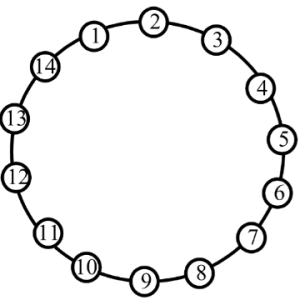
Ring WDM networks implementing communication between two fixed points are very well established technology, in particular, for carrying SONET over the WDM. Such simple networks with fixed WDM lighpaths happen to be analyzed in many detail. Fairly detailed first principle models for transmission power dynamics exist for such networks. These models are implemented in industrial software allowing engineering design calculations and dynamical simulation of these networks. Such models could possibly have very high fidelity, but their setup, tuning (model parameter identification) and exhaustive simulations covering a variety of transmission regimes are potentially very labor intensive. Adding description of new network components to such model could need a major effort.


14-nodes Mesh WDM
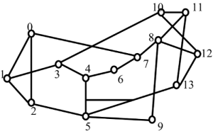
The problems with detailed first principle models is going to be greatly exacerbated for future Mesh WDM networks. The near future core optical networks will be transparent to wavelength signals on a physical layer. In such network, each wavelength signal travels through the optical core between electronic IP routers around the optical network edge using the information contents unchanged. The signal power is attenuated in the passive network elements and boosted by the optical amplifiers. The lightpaths is going to be dynamically provisioned by Optical Cross-Connects (OXCs), routers, or switches independently on the underlying protocol for data transmission. Such network is basically a circuit switched network. It might experience complex transient processes of the average transmission power for every wavelength signal at the event of the lightpath add, drop, or re-routing. A mix of the signal propagation delay and channel cross-coupling might result in the transmission power disturbances propagating across the network in closed loops and causing stamina oscillations. Such oscillations were observed experimentally. Additionally, the transmission power and amplifier gain transients could be excited by changes in the average signal power because of the network traffic burstliness. If for some period of time the wavelength channel bandwidth is not fully utilized, this could result in a loss of the average power (average temporal density of the transmitted information pulses).

First circuit switched optical networks are already being designed and deployed. Fraxel treatments develops rapidly for metro area and long term networks. Engineering design of circuit switched networks is complicated because performance has to be guaranteed for all possible combinations of the lightpaths. Further, as such networks develop and grow, they potentially need to combine heterogenous equipment from a variety of vendors. A system integrator (e.g., Fiberstore) of such network might be different from subsystems or component manufacturer. This creates a necessity of developing adequate means of transmission power dynamics calculations which are suitable for the circuit switched network business. Ideally, these methods should be modular, independent on the network complexity, and use specifications on the component/subsystem level.

Fiberstore has technical approach to systems analysis that’s to linearize the nonlinear system around a fixed regime, describe the nonlinearity like a model uncertainty, and apply robust analysis that guarantees stability and gratifaction conditions within the presence of the uncertainty. For a user of the approach, there is no need to understand the derivation and system analysis technicalities. The obtained results are very simple and relate performance to basic specifications of the network components. These specifications are somewhat not the same as those widely used in the industry, but could be defined from simple experimentation using the components and subsystems. The obtained specification requirements may be used in growth and development of optical amplifiers, equalizers, optical attenuators, other transmission signal conditioning devices, OADMs, OXCs, and any other optical network devices and subsystems influencing the transmission power.

Application of Optical Add-Drop Multiplexer

What’s the Optical Add-drop Multiplexer?

The optical add-drop multiplexers (OADM) are used in wavelength-division multiplexing systems for multiplexing and routing different channels of light into or out of a single mode fiber (SMF). This is a type of optical node, which is generally used for the construction of optical telecommunications networks. An OADM may be considered to be a specific type of cross connect cabinet.

A traditional OADM consists of three stages: an optical demultiplexer, and optical multiplexers, and between them a method of reconfiguring the paths between the optical demultiplexer, the optical multiplexer and a set of ports for adding and dropping signals. The optical demultiplexer separates wavelengths in an input fiber onto ports. The reconfiguration can be achieved by a fiber patch panel or by optical switches which direct the wavelengths to the optical multiplexer or to drop ports. The optical multiplexer multiplexes the wavelength channels that are to continue on from demultiplexer ports with those from the add ports, onto a single output fiber.

Principles of OADM technology

General OADM node can use four port model (Figure 1) to represent, includes three basic functions: Drop required wavelength signal, Add rumored signal to other wavelengths pass through unaffected. OADM specific network process is as follows: WDM signal coming from the line contains mangy wavelength signals into OADM’s “MainInput” side, according to business required, from many wavelength signals to selectively retrieved from the end (Drop) output desired wavelength signal, relative to the end from the Add the wavelength of the input signal to be transmitted. While the other has nothing to do with the local wavelength channels directly through the OADM, and rumored signals multiplexed together, the line output from the OADM (Main Output) Output.

OADM node technical classification

Optical drop multiplexer network technologies can be divided into two types, fixed optical drop multiplexer (Fixed OADM, FOADM) and reconfigurable optical drop multiplexer (Reconfigurable OADM, ROADM).

Fixed Optical Drop Multiplexer (FOADM)

FOADM to filter as the main component, and its function is fixed to join or retrieve certain light wavelengths. General common FOADM can be divided into three types, namely Thin Film Filter type (TFF type), Fiber Bragg Grating (FBG type) and integrated planar Arrayed Waveguide Gratings (AWG type).

TFF FOADM

Thin Film Filter (TFF FOADM)

TFF FOADM using thin film between the filtering effect of the different refractive index.

Fiber Bragg Grating (FBG FOADM)

FBG FOADM use of fiber Bragg grating filtering effect, with two circulator can become FOADM.

Arrayed Waveguide Gratings (AWG FOADM)

AWG FOADM gererally used in semiconductor fabrication processes, the integration of different refractive index material is formed on a flat substrate in a planar waveguide, when different wavelength light source is incident through the couping after the import side, due to take a different path length, while the different phase delay caused by different wavelengths and thus produce certain wavelengths in the export side to form a constructive or destructive interference, making waves in the export side, the different wavelengths will follow the design on a different channel to reach, and thus achieve FOADM function.

Reconfigurable Optical Add/Drop Multiplexer (ROADM)

ROADM can always be adjusted with the distribution network to add and drop wavelength, which reconstruct the network resource allocation, the flexibility to meet the requires of modern urban network, so a flexible ROADM features, plus optical switch substantial advantage, making the current fastest growing ROADM based optical switches based ROADM (switch based OADM). ROADM mainly be the optical switch, multiplexer and demultiplexer composed, Switch-based OADM, mainly divided into Wavelength independent switch array and wavelength selection switch.

Wavelength independent switch array

Type 1: Wavelength independent switch array

Wavelength selective switch

Type 2: Wavelength selective switch

All kinds of optical drop multiplexer performance comparison

optical drop multiplexer performance

OADM network applications

WDM ROADM optical fiber suitable for different network environments

OADM network applications

OADM in the metropolitan network development tendency

1. Arbitrary choice must be retrieved, adding wavelength, the wavelength can take advantage of the limited resources, the node can be retrieved with the need to do to join the adjustment of the signal wavelength, and has a remote control functions. This can provide dynamic reconfiguration of optical communications network capable ROADM will be connected to the backbone network critical devices. And FOADM is used for wavelength demand network access will be smaller parts to reduce costs. Furthermore, ROADM use to all kinds of Tunable Laser, unable Filter, or wavelength selective optical switches and other components.

2. Must be able to convert incompatible wavelength suitable for the backbone network will be transmitted wavelengths. Therefore, OADM be combined with wavelength conversioin Transponder or other functional components.

3. Must be able to compensate for the node to make acquisistion, adding such action energy loss. Therefore, OADM optical amplifiers must be combined with functional components.

4. Wavelength signals related specifications, such as: the signal to noise ratio (S/N), the energy balance between the signal wavelength, etc., are required to meet network requirements. Therefore must be combined OADM variable optical attenuators (VOA), dispersion compensation module (DCM) and other components.

How Much Do You Know About OADM

The OADM, or optical add drop multiplexer, is a gateway into and out of a single mode fiber. In practice, most signals pass through the device, but some would be “dropped” by splitting them from the line. Signals originating at that point can be “added” into the line and directed to another destination. An OADM may be considered to be a specific type of optical cross-connect, widely used in wavelength division multiplexing systems for multiplexing and routing fiber optic signals. They selectively add and drop individual or sets of wavelength channels from a dense wavelength division multiplexing (DWDM) multi-channel stream. OADMs are used to cost effectively access part of the bandwidth in the optical domain being passed through the in-line amplifiers with the minimum amount of electronics.

OADMs have passive and active modes depending on the wavelength. In passive OADM, the add and drop wavelengths are fixed beforehand while in dynamic mode, OADM can be set to any wavelength after installation. Passive OADM uses Filter WDM, fiber gratings, and planar waveguides in networks with WDM systems. Dynamic OADM can select any wavelength by provisioning on demand without changing its physical configuration. It is also less expensive and more flexible than passive OADM. Dynamic OADM is separated into two generations.

A typical OADM consists of three stages: an optical demultiplexer, an optical multiplexer, and between them a method of reconfiguring the paths between the optical demultiplexer, the optical multiplexer and a set of ports for adding and dropping signals. The optical demultiplexer separates wavelengths in an input fiber onto ports. The reconfiguration can be achieved by a cross connect panel or by optical switches which direct the wavelengths to the optical multiplexer or to drop ports. The optical multiplexer multiplexes the wavelength channels that are to continue on from demultipexer ports with those from the add ports, onto a single output fiber.

Physically, there are several ways to realize an OADM. There are a variety of demultiplexer and multiplexer technologies including thin film filters, fiber Bragg gratings with optical circulators, free space grating devices and integrated planar arrayed waveguide gratings. The switching or reconfiguration functions range from the manual fiber patch panel to a variety of switching technologies including microelectromechanical systems (MEMS), liquid crystal and thermo-optic switches in planar waveguide circuits.

CWDM and DWDM OADM provide data access for intermediate network devices along a shared optical media network path. Regardless of the network topology, OADM access points allow design flexibility to communicate to locations along the fiber path. CWDM OADM provides the ability to add or drop a single wavelength or multi-wavelengths from a fully multiplexed optical signal. This permits intermediate locations between remote sites to access the common, point-to-point fiber message linking them. Wavelengths not dropped, pass-through the OADM and keep on in the direction of the remote site. Additional selected wavelengths can be added or dropped by successive OADMS as needed.

FiberStore provides a wide selection of specialized OADMs for WDM system. Custom WDM solutions are also available for applications beyond the current product designs including mixed combinations of CWDM and DWDM.