10G DWDM Tunable XFP – Up to 80 km Reach

With the spread of cloud computing and mobile broadband service, the volume of communications traffic has rapidly increased. In order to enable high-capacity optical networks, using a single optical fiber for optical signals of several different wavelengths in DWDM system is widely used. For this reason, tunable transceiver that enables ROADM functionality in next-generation networks is becoming more and more popular. In today’s market, there are mainly two kinds of tunable DWDM transceivers: tunable XFP and tunable SFP+. This article will take you to explore the DWDM C-band tunable XFP transceiver with 40 / 80 km transmission distance options.

10g-dwdm-tunable-xfp-transceiver

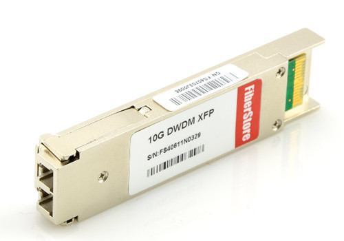
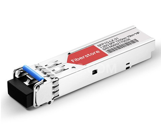
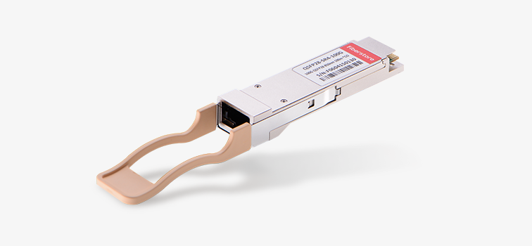
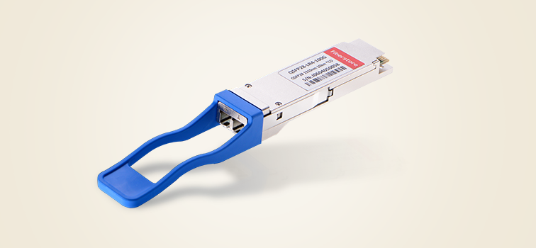
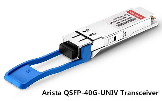
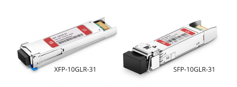
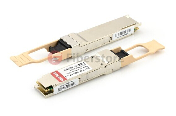
Figure 1: Cisco Compatible Tunable DWDM XFP Transceiver

Tunable XFP Transceiver

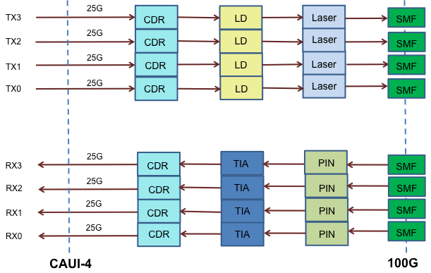
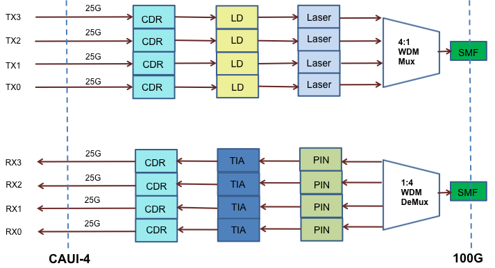
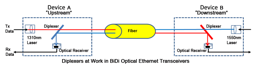
Tunable XFP transceiver is an integrated fiber optic transceiver that provides a high-speed serial link at signaling rates from 9.95 Gbps to 11.35 Gbps. It complies with the ITU-T G.698.1 S-D100S1-2D standard with 50GHz channel spacing for SONET/SDH, IEEE DWDM 10GBASE-ZR for 40 or 80 km reach (Ethernet), and DWDM 10G FC (Fibre Channel) for 40 or 80 km reach applications. Tunable DWDM XFP can be tuned from channel C17 (1563.86nm) to C61 (1528.38nm). The maximum distance of this transceiver on a single mode fiber is up to 80 km. As mentioned above, tunable XFP optical transceiver is a full-duplex serial electric, serial optical device with both transmit and receive functions contained in a single module. On the transmit side, the 10 Gbps serial data stream is recovered, retimed, and passed to a modulator driver. The modulator driver biases and modulates a C-band-tunable integrated laser Mach-Zehnder (ILMZ), enabling data transmission over singlemode fiber through an industry-standard LC connector. On the receive side, the 10 Gbps optical data stream is recovered from an APD/transimpedance amplifier, retimed, and passed to an output driver. This module features a hot-pluggable XFI-compliant electrical interface. Here is a simple picture showing its working process.

function diagram of tunable xfp

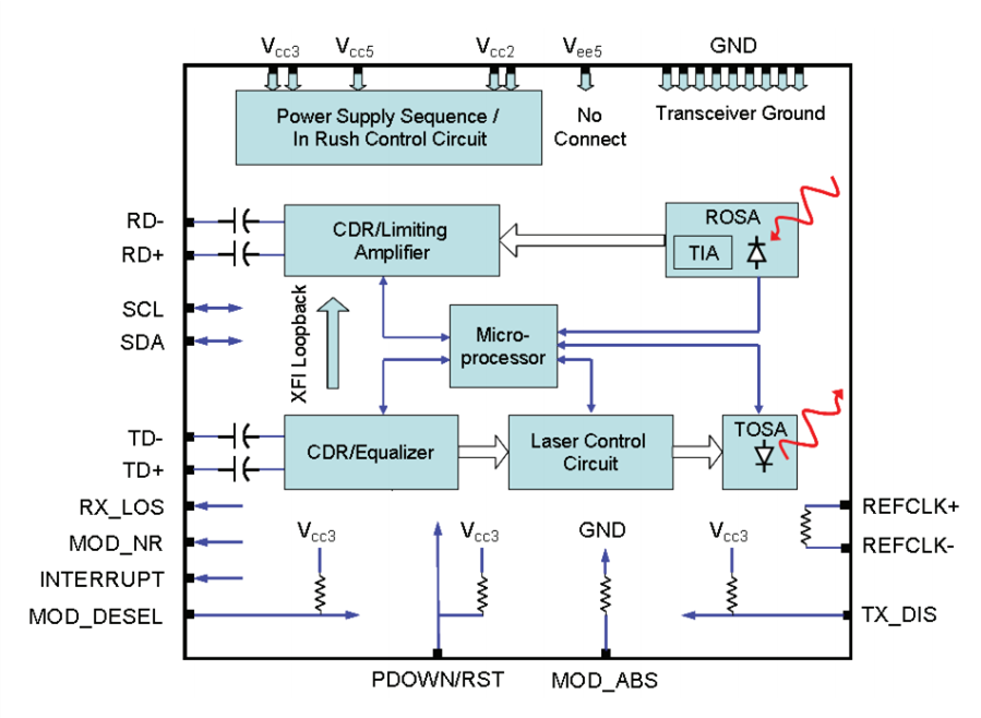
Figure 2: Working Process of Tunable Transceiver

Tunable XFP Optics Specifications:

  • 50 GHz ITU channel spacing with intergrated wavelength locker
  • Available in all C-Band Wavelengths on the DWDM ITU grid
  • Available distances 40 or 80 km
  • Supports 9.95Gb/s to 11.35Gb/s
  • Built-in Digital Diagnostic Functions
  • Tempereature Range: -5°C to 70°C

Two Transmission Distance Options: 40 km or 80 km

There are two transmission distance options for XFP tunable transceiver: 40 km or 80 km. Tunable XFP DWDM 80 km transceiver is designed for long distance optical communications up to 80 km with signaling rates up to 10Gbps. Obviously, the main difference is transmission distance. On account that 10G tunable DWDM XFP optical transceiver provides digital diagnostic functions via a 2-wire serial interface, which allows real-time access to the following operating parameters: transmitted optical power, received optical power, transceiver temperature, laser bias current and transceiver supply voltage. Therefore, the differences between 40 km tunable XFP and 80 km tunable XFP mainly lie on theses parameters. One thing to note is that 40 km tunable XFP optics is designed with high performance PIN receiver, while the 80 km tunable XFP transceiver is APD receiver. The APD (avalanche photodiode) receiver employed in these extended-reach optical transceivers has an enhanced sensitivity to allow for these extended distance fiber runs. However, it is to be noted that the input power is typically between -7 and -24 dBm. Therefore, the receiver sensitivity between these two distance has a big difference. Generally, the max receive dBm of 40 km tunable XFP transceiver is -15, while the 80 km tunable XFP transceiver is -24. And for power budget, 40 km tunable XFP is 14dB while a distance up to 80 km is up to 22dB power budget. The following table lists the main differences.

40km 80km tunable xfp

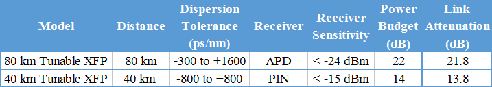
Table 1: 40 km Tunable XFP VS. 80 km Tunable XFP

Conclusion

In general, the channel switching of tunable switches can enable the service operators to turn up circuits faster and reduce their sparing costs dramatically in today’s DWDM systems. On the other hand, tunable optics are usually two or four times more expensive than the regular static DWDM optical module, because a special tunable laser is applied in it. Tunable XFP optical transceiver provides a full C-band window covering 1528nm to 1566nm for DWDM optical networks, which meets the need of rapid increase in the volume of communications traffic from telecom carrier and operator. The tunable DWDM XFP module can replace the fixed DWDM channel XFP transceivers that are currently used, while reduce the large stock since all wavelengths can now be covered with one transceiver module.

Model Frequency Wavelength Fiber Type Connector Price on FS.COM
ONS-XC-10G-C 50 GHz 1563.86~1528.3 SMF LC $1,400
XFP-10G-CBAND-T50-ZR 50 GHz 1563.86~1528.3 SMF LC $1,400
NTK583AAE6 50 GHz 1563.86~1528.3 SMF LC $1,400
TDXFP-10GHXXX-80 50 GHz 1563.86~1528.3 SMF LC $1,400
TDXFP-10GHXXX-40 50 GHz 1563.86~1528.3 SMF LC $1,400

Related Article: Wavelength Switching Solution: Tunable XFP Transceiver

Compatible SFP Transceivers for HP 1810-48G Switch (J9660A)

Today, small and midsize businesses are embracing mobile and cloud technologies to improve employee productivity and engage with customers. More business needs an affordable, high-performance and secure wired and wireless infrastructure that can support the growing number of mobile devices and cloud-based applications. When asking for a recommendation for SMB switches, many people always recommend the HP because it has most of the same capabilities such as full management capability, rock solid operation and great support (as the Cisco), but at half the price. And HP 1810-48G switch is one of such SMB switches. This article intends to give a simple introduction to HP 1810-48G switch and provide compatible SFP transceiver solutions for it.

HP 1810-48G Switch (J9660A)

HP 1810-48G Switch (J9660A)

The HP 1810-48G switch is a basic smart managed Gigabit Ethernet Layer 2 switch that is designed for small businesses. This HP ProCurve 48 port gigabit switch has four additional true Gigabit Ethernet SFP ports (52 total active ports) for fiber connectivity, which supports Gigabit-SX, -LX, or 100-FX and SFP 1G RJ-45 copper connections. Besides, it supports flexible deployment options, including mounting on walls or ceilings, under tables, or desktop operation. More than anything, it comes with an anti-theft protection Kensington Lock slot, which allows switches to be secured in open-space deployments. A HP 1810-48G switch also has some customizable features, including VLANs, Spanning Tree and link aggregation trunking.

HP 1810-48G switch

Key Features or Benefits:

  • Customized operation using intuitive Web interface
  • Flexible connection and deployment options
  • Layer 2 operation at wire speeds
  • VLANs and link aggregation support
HP ProCurve Mini-GBICs and SFPs

HP ProCurve transceivers as the part of the networking accessories that are applied to their corresponding switches or routers. Thus, it is also important to get some knowledge of the HP ProCurve Mini-GBICs and SFPs. HP ProCurve Mini-GBICs and SFPs have three version: revision A, revision B and revision C. Though there is no big difference between these three version, some improvement will be added in the newest version. The “revision C” Mini-GBICs (eg. J4858C, J4859C, J4860C) are supported in all ProCurve products that support Mini-GBICs. In addition, “revision B” and “revision C” mini-GBICs can be used together in any ProCurve switch that supports mini-GBICs. FS.COM can support the 100% compatible HP ProCurve Mini-GBICs and SFPs at version A, B and C, such as J4858A/B/C, J4859A/B/C, J4860A/B/C.

HP Compatible SFP Transceivers for HP 1810-48G Switch (J9660A)

According to HP ProCurve Networking Mini-GBIC Support Matrix, we can easily find out which Mini-GBICs and SFPs are supported for HP 1810-48G Switch (J9660A).

HP X111 100M SFP LC FX Transceiver (J9054C)

The HP J9054C compatible SFP transceiver provides 100Base-FX throughput up to 2km over multi-mode fibre (MMF) at a wavelength of 1310nm using a LC connector. FS is guaranteed to be 100% compatible with the equivalent HP transceiver. This hot swappable transceiver has been programmed, uniquely serialized and data-traffic and application tested to ensure that it will initialize and perform identically. It is built to comply with multi-source agreement (MSA) standards to ensure seamless network integration.

J9054C

HP X121 1G SFP LC SX Transceiver (J4858C)

This SFP (mini-GBIC) transceiver module is designed for use with HP network equipment and is equivalent to HP part number J4858C. It provides 100Base-FX throughput up to 550m over multi-mode fibre (MMF) at a wavelength of 850nm using a LC connector. The transceiver is hot-swappable input/output device which allows a Gigabit Ethernet port to link with a fibre optic network. And this transceiver may be mixed and deployed with other OEM or third party transceivers and will deliver seamless network performance.

J4858C

HP X121 1G SFP LC LX Transceiver (J4859C)

HP ProCurve J4859C 1000BASE-LX-LC Mini-GBIC is a small form factor pluggable (SFP) gigabit LX transceiver that provides a full-duplex gigabit solution up to 10 km (singlemode) or 550 m (multimode). It is an SFP format gigabit transceiver with LC connectors using LX technology.

J4859C

HP X121 1G SFP RJ45 T Transceiver (J8177C)

J8177C is a small form-factor pluggable (SFP) Gigabit copper transceiver with RJ45 connectors using 1000BaseT technology, that provides a full-duplex Gigabit solution up to 100m on Category 5 or better cable. It is guaranteed compatible for all HP switch and router product lines. This transceiver can be mixed and deployed with HP OEM transceivers for seamless network performance and interoperability.

J8177C

Precautions:

To remove the J8177C from a Mini-GBIC slot on the switch, follow this procedure:

1. Remove the attached cable from the Mini-GBIC.

2. Without forcing the latch, swivel the latch 90 degrees to the unlocked position.

CAUTION: Do not force the latch! If the latch does not easily swivel 90 degrees, move the latch back to the locked position, re-seat the Mini-GBIC by pressing it into the switch, then repeat step 2.

Conclusion

FS.COM is a professional manufacturer and supplier of optical networking solutions. We can supply 100% compatible fiber optic transceiver modules of many brands, like HP, Cisco, Dell, Juniper etc. with a incredible discount. About HP 1810-48G and other switches, you can find a full product line of our New HP transceivers with a good price and enjoy same-day shipping. In addition, according to your requirements, we welcome any inquiry for customized fiber optical transceiver. FS’s aim is offering the best quality products and perfect solutions, saving customers’s time and money, making customers enjoy personalization.

Which 10G SFP+ Optics Are Compatible with Intel X520 Adapter?

The escalating deployments of servers with multi-core processors and demanding applications are driving the need for 10 Gbps connections. Intel X520 10 GbE Adapter is the most flexible and scalable Ethernet adapters for today’s demanding data center environments. At the same time, 10G SFP+ optics play the most important role for its 10G connectivity. But seriously, do you know which 10G SFP+ optics are compatible with the Intel Ethernet converged network adapter X520 series? This blog will give you solutions.

About Intel X520 Adapter

Intel X520 adapter is powered by reliable and proven 10G Ethernet technology, which offers high performance for high-IO intensive applications and showcase the next generation in 10 GbE networking features for the enterprise network and data center. It is designed for multi-core processors, which supports for technologies such as multiple queues, receive-side scaling, multiple MSI-X vectors and Low Latency Interrupts. It addresses the demanding needs of the next-generation data center by running mission-critical applications in virtualized and unified storage environments. In a multicore platform, the Intel X520 adapter supports Intel I/O Virtualization Technology (IOVT), which helps accelerate data across the platform, therefore improving application response times. For virtualized environments, it offers advanced features with VMDq (Virtual Machine Device Queues) that lower processor utilization and increase I/O performance.

Intel X520 Dual Port 10GbE SFP+ Adapter

Figure 1. Intel X520 Dual Port 10GbE SFP+ Adapter

The Intel X520 adapter provides SFP+ based connectivity options (fiber or DAC cabling). Intel X520 adapters are provided with 7 models: X520-QDA1, X520-DA2, X520-SR1, X520-SR2, X520-DA1OCP, X520-DA2OCP and X520-LR1. X520-SR1 is shipped with 1 SR SFP+ Optic,  X520-SR2 has dual-port and is shipped with 2 SR SFP+ Optics, X520-LR1 has single-port and is shipped with 1 LR SFP+ Optic, and X520-DA2 has dual-port and does not ship with any optics or cables, which is the most suitable one for 10G SFP+ Optics and the most popular one on the market. The following table lists the detailed information of Intel X520 adapter series in Table 1.

Intel X520 Adapter Product Code Connector and Cable Cable Type Ports
X520-QDA1 QSFP+ direct attach copper (4x10GbE mode) QSFP+ direct attached twinaxial cabling up to 10m Single port
X520-SR1 Fiber optic MMF up to 300 m Single port
X520-SR2 Fiber optic MMF up to 300 m Dual port
X520-DA2 SFP+ direct attach copper SFP+ direct attached twinaxial cabling up to 10 m Dual port
X520- LR1 Fiber optic SMF up to 10 km Single port
X520-DA1OCP SFP+ direct attach copper SFP+ direct attached twinaxial cabling up to 10 m Single port
X520-DA2OCP Copper SFP+ direct attached twinaxial cabling up to 10 m Dual port

Table 1: Intel X520 Series Adapters

10G SFP+ Optics for Intel X520 Adapter

A 10 Gigabit Ethernet network is essential for businesses that demand high bandwidth for virtualization and fast backup and restore for an ever-growing amount of data. To ensure maximum flexibility, Intel X520 adapters support the ability to mix any combination of the SFP+ optical modules, direct attach copper cables, or 1000BASE-T SFP modules. Besides, 10G SFP+ Optics are available in both short-range (SR) 850 nm and long range (LR) 1310 nm options. This enables customers to create the configuration that meets the needs of their data center environment.

10G SFP+ Optical Modules for Intel X520

Intel Ethernet SFP+ SR optics and Intel Ethernet SFP+ LR optics are the only 10 Gbps optical modules supported. Other brands of SFP+ modules are not allowed and can’t be used with the X520 adapters. The following table lists the supported 10Gb Ethernet SFP+ optical transceivers for Intel X520 adapters in Table 2. (Note: Other brands of SFP+ optical modules will not work with the Intel Ethernet Server Adapter X520 Series.)

10G SFP+ Optical Modules
Name Intel Product Code (MFG PART#) FS P/N Type
Intel 10G SFP+ SR Optical module E10GSFPSR SFP-10GSR-85 Dual Rate 10GBASE-SR/1000BASE-SX
Intel 10G SFP+ LR Optical module E10GSFPLR SFP-10GLR-31 Dual Rate 10GBASE-LR/1000BASE-LX

Table 2: 10G SFP+ Optical Transceivers for Intel X520 Adapters

1000BASE-T SFP Modules for Intel X520

Some 1000BASE-LX and 1000BASE-SX modules can work with Intel Ethernet Converged Network Adapter X520 series. These modules referred to only highlight specifications and compatibility with Intel Ethernet server adapter X520 series. The table lists the tested modules in Table 3. Other similar modules may work but have not been tested (many similar modules can be purchased in FS.COM). Remind you to use your own discretion and diligence to purchase modules with suggested specifications from any third party.

1000BASE-T SFP Modules
Name Intel Product Code (MFG PART#) FS P/N Type
Avago Gigabit Ethernet Module ABCU-5710RZ SFP-GB-GE-T 1000BASE-SX
Intel Gigabit Ethernet Module TXN22120 SFP1G-LX-31 1000BASE-LX

Table 3: 1000BASE-T SFP Modules for Intel X520 Adapters

10G SFP+ Direct Attach Copper Cables (10G SFP+Cu) for Intel X520

A DAC cable is a 2-pair shielded copper cabling terminated with SFP+ electrical modules. Intel X520 Adapters require that any SFP+ passive or active limiting direct attach copper cable should comply with the SFF-8431 v4.1 and SFF-8472 v10.4 specifications. SFF-8472 Identifier must have value 03h (You can verify the value with the cable manufacturer). The maximum cable length for passive cables is 7 meters. Support for active cables requires Intel Network Connections software version 15.3 or later. The following table lists the fully compatible 10Gb DAC cables for Intel Ethernet server adapter X520 series in Table 4.

10G SFP+ DAC Cables
Name Product Code (MFG PART#) FS P/N Type
Intel Ethernet SFP+ Twinaxial Cable, 1 meter XDACBL1M SFP-10G-DAC 10G SFP+ Passive Direct Attach Copper Twinax Cable
Intel Ethernet SFP+ Twinaxial Cable, 3 meter XDACBL3M SFP-10G-DAC 10G SFP+ Passive Direct Attach Copper Twinax Cable
Intel Ethernet SFP+ Twinaxial Cable, 5 meter XDACBL5M SFP-10G-DAC 10G SFP+ Passive Direct Attach Copper Twinax Cable

Table 4: 10G DAC cables for Intel X520 Adapters

QSFP+ Breakout Cables for Intel X520

The new QSFP+ single-port X520-QDA1 can connect the server to the latest 40GbE switches with a single cable operating in 4x10GbE mode. This adapter can also utilize existing 10GbE SFP+ switches using the QSFP+ to 4xSFP+ breakout cable. The QSFP+ adapter supports direct attach copper cables and Intel Ethernet QSFP+ SR optical transceivers. Intel Ethernet QSFP+ breakout cables have one QSFP+ connector on one end and break out into four SFP+ connectors on the other end for direct attachment to SFP+ cages. The following table lists the Intel Ethernet QSFP+ cable for Intel adapter X520-QDA1 in Table 5.

Intel Ethernet QSFP+ Breakout Cables for Intel Adapter X520-QDA1
Name Product Code (MFG PART#) FS P/N
Intel Ethernet QSFP+ breakout cable, 1 meter QSFP-4SFP10G-CU1M QSFP-4SFP10G-DAC
Intel Ethernet QSFP+ breakout cable, 3 meter QSFP-4SFP10G-CU3M QSFP-4SFP10G-DAC
Intel Ethernet QSFP+ breakout cable, 5 meter QSFP-4SFP10G-CU5M QSFP-4SFP10G-DAC

Table 5: QSFP+ Breakout Cables for Intel Adapter X520-QDA1

Summary

From what we have discussed, 10G SFP+optics are determined to the data transmission of Intel X520 adapters. SFP+ SR Optics, SFP+ LR optics, 1000BASE-T SFP modules, 10G SFP+ direct attach copper cables and QSFP+ breakout cables are available stock in FS.COM. All SFP+ cables are 100% tested to ensure compatibility and quality. Welcome to visit www.fs.com.

Related Articles

Copper SFP vs Optical SFP: Which One Is the Best to Use?

How Many Types of SFP Transceivers Do You Know

A Comprehensively Understanding of Cisco 10G SFP+

Examples of CWDM Network Deployment Solution

Based on the same concept of using multiple wavelengths of light on a single fiber, CWDM and DWDM are two important technologies in fiber optical communications. As we all know, although the transmission distance of CWDM network is shorter than that of DWDM, it costs less and has the scalability to grow fiber capacity as needed. This article intends to give a simple introduction of components in CWDM networks and to explore some examples of CWDM network deployment cases.

Common Components Used in CWDM Networks
CWDM Mux/Demux

CWDM Mux/Demux, which is based on the film filter technology, is the basic component in CWDM networks. It can combine up to 4, 8 or 16 different wavelength signals from different fiber extenders to a single optical fiber, or it can separate the same wavelengths coming from a single CWDM source. That’s why CWDM can extend existing fiber capacity.

CWDM OADM (Optical Add-Drop Multiplexer)

A CWDM OADM is a device that can add (multiplex) and drop (demultiplex) channels on both directions in a CWDM network. It can add new access points anywhere in CWDM systems without impacting the remaining channels traversing the network. With this ability of OADM, the access points can be added to liner, bus, and ring networks, where the dual direction ring design provides redundant protected architecture.

CWDM Optical Transceiver

Optical transceiver is a necessary element in optical networks. And CWDM optical transceiver is a type of module supporting CWDM network application with CWDM wavelengths. When connected with CWDM Mux/Demux, CWDM transceiver can increase network capacity by allowing different data channels to use separate optical wavelengths (1270nm to 1610nm) on the same fiber. And the common CWDM transceiver type is SFP, SFP+, XFP, XENPAK, X2, etc.

CWDM Network Deployment Solution
Example One

Description: there are five buildings (Sheriff, Courthouse, Admin, Police & Fire, & Public Works) connected via multimode fiber cables (MMF) or single mode fiber cables (SMF). These buildings are linked via multimode SFPs in an existing D-link switches to create one network for internal use of the city offices. Below is a simple graph to show the situation.

CWDM Network 1

Requirements: the goal is to install a single mode fiber network in town to connect numerous buildings. Some of these buildings have access to the city LAN. The Public Works building need to connect with Youth & Recreation Center, Library, Immanuel Lutheran School and the Senior Center. And all these buildings should have unfiltered Internet. Besides, the Waster Water Treatment Plant should be connected passing through the Senior Center. All these services are achieved using CWDM technology.

Solution: according to the requirements, this is a CWDM networks with several buildings to connect with. Here is the solution diagram.

CWDM Network

In the diagram above, we can see there is an 8CH CWDM Mux/Demux connected with the switches. According to the requirements, Youth & Recreation Center, Library, Immanuel Lutheran School and Senior Citizen Center should be connected with the Public Works and need unfiltered services. Therefore, a 4CH CWDM OADM is placed after the CWDM Mux/Demux. Then the four wavelengths will be drop and into the four buildings. In addition, another CWDM OADM is deployed in Senior center to connect the Waster Water Treatment Plant, to meet the requirement. And each site also needs to use CWDM optical transceivers.

Example Two

Description: on site A, there are three Ethernet switches and a T3 router. And their working wavelengths 1470nm, 1490nm, 1510nm, 1530nm and 1610nm. Other three sites B, C, and D also have three Ethernet switches. And a T3 router is in site E. As the following figure shows.

CWDM OADM

Requirements: Considering the cost, all the wavelengths should be transmitted on a single fiber using CWDM technology.

Solution: according to the requirements, here is a simple diagram showing the solution.

CWDM Mux Demux

In order to save cost, a 4CH CWDM Mux/Demux is used to multiplex four wavelengths (from three switches and one router) into one single fiber. At the first site B, a 1CH CWDM OADM is installed to remove one wavelength which is associated with network B. And other three sites are the same—dropping one wavelength associated with corresponding switch or router.

Summary

This article mainly introduces two CWDM network deployment examples. All the components like the CWDM Mux/Demux, CWDM OADM and CWDM transceiver are available in FS.COM. If you are interested in them, please contact us via sales@fs.com.

Related article:Differences between CWDM and DWDM

100G QSFP28 Transceiver Overview and How to Choose It

It’s no denying that today’s data centers are moving from 10G to 40G and 100G quickly. On this road, data explosion is getting faster, which result in great demand for cost-effective 100G optics. And the commonly used 100G qsfp28 transceiver are CFP, CFP2, CFP4 and QSFP28, especially the QSFP28. Today this article mainly introduces four types of 100G QSFP28 transceiver and the comparison between them to help you choose a suitable one.

Overview of 100G QSFP28 Transceiver
100G SR4 Transceiver

The 100G SR4 transceiver is a full-duplex optical module, offering four independent transmit and receive channels, each capable of 25Gb/s operation for an aggregate data rate of 100Gbps to 100 meters on OM4 multimode fiber (MMF). It’s fully compliant with QSFP28 Multi-Source Agreement (MSA) and can offer increased port density and total system cost savings for future data center and networking use. When connected to transmission links, an optical fiber ribbon cable is plugged into the QSFP28 modules receptacle via the MTP/MPO connector, and the guide pins inside the receptacle ensure the proper alignment. Besides, this QSFP28 transceiver offers high functionality and feature integration, accessible via a two-wire serial interface which is available for more complicated control signals and digital diagnostic information.

100G-QSFP28-SR4

100G QSFP28 LR4 Transceiver

The 100G LR4 transceiver is a fully integrated 4x25Gbit/s optical transceiver module, designed for use in data centers and high performance computing network links on up to 10km of single mode fiber (SMF). They are compliant with QSFP28 MSA, IEEE 802.3ba and IEEE 802.3bm CAUI-4. When connected to data transmission links, it converts four input channels of 25Gb/s electrical data to four channels of LAN WDM optical signals and then multiplexes them into a signal channel for 100Gb/s optical transmission. While on the receiver side, the module demultiplexes the 100G optical signals into four output channels and converts them into electrical data.

100G-QSFP28-LR4

100G QSFP28 PSM4 Transceiver

Defined by the 100G PSM4 MSA, qsfp 100g psm4 s is a little different from 100g SR4 transceiver. It uses four parallel lanes (four transmit and four receive) operating on each direction. Each lane carries 25G optical transmission. Therefore, eight single mode fibers are needed when PSM4 is deployed in transmission links. And the reach of PSM4 is up to 500m on single mode fiber, compensating for the transmission distance defect between 100g SR4 and 100g LR4 transceiver.

100G-QSFP28-PSM4

100G QSFP28 CWDM4 Transceiver

CWDM4 routes four 25G optical transmissions down a single fiber, which is like the qsfp 100g psm4 s. But it has longer reaches of up to 2km on SMF. And CWDM4 uses multiplexer and de-multiplexer to reduce the number of fibers to two rather than eight. When connected into transmission links, on the transmitting side, signals are multiplexed into one channel and transmitted through the SMF; then on the receiving side, the incoming signals are demultiplexed into four separated channels (shown as below).

100G-QSFP28-CWDM4

How to Choose?

With a number of 100G optical transceivers emerged, many factors should be taken into consideration when choose suitable transceivers. The key features of the 100G QSFP28 transceivers are listed below.

100g QSFP28 Transceivers

As shown in the table, cable type, interface type, fiber count and reach are needed to be considered when purchasing transceivers. For example, in the terms of reach, except the shortest (100g SR4) and the longest (100g LR4), qsfp 100g psm4 s and CWDM4 are battling out in the 2km range. Here is a simple chart that may help to illustrate the difference between the two. As have mentioned above, qsfp 100g psm4 s doesn’t use MUX/DEMUX, which determines its price is lower than CWDM4. However, as the transmission distance increases, the cost will grow quickly since it deploys eight-fiber transmission links.

PSM4 vs CWDM4

In summary, there are various types of 100G qsfp28 transceiver modules on the market. Different companies and operators have different requirements for their links and applications. So choosing a suitable 100G QSFP28 transceiver should be based on your practical situations. If you want to know more about 100G QSFP28 transceivers, welcome to visit FS.COM.

Getting to Know About QSFP-40G-UNIV Transceiver

As the switching applications requiring higher bandwidth increased, the need to upgrade from 10G to dense 40 Gigabit Ethernet switching connection also goes on rise. But the optical transceivers widely used at present require to redesign the data center layout if migrating to 40G, for the existing fiber infrastructure cannot satisfy this migration requirement. However, the QSFP-40G-UNIV transceiver can solve this problem perfectly. Why QSFP-40G-UNIV transceiver can resolve the problem successfully? Let’s first to know the basics about it.

Basics of QSFP-40G-UNIV Transceiver

The “UNIV” in item “QSFP-40G-UNIV” means “Universal”. As we all know, common optical transceiver only can operate either on single-mode fiber (SMF) or multimode fiber (MMF), but it can work on both types of fibers. Therefore, QSFP-40G-UNIV transceiver is also called SMF&MMF 40G transceiver or QSFP 40G universal transceiver. This transceiver is a pluggable optical transceiver in an industry standard QSFP+ form factor. It has four channels of 10G multiplexed inside the module to transmit and receive an aggregate 40G signal over a single pair of single-mode or multimode fiber. And it uses a duplex LC connector that makes it work with a wide range of fiber optic cables, including multi-mode OM3 and OM4 and single mode (OS1). Besides, QSFP-40G-UNIV transceiver supports distances up to 150 m over OM3 or OM4 multimode fiber and up to 500 m over single-mode fiber (different vendor may have different specifications).

ariste-qsfp-40g-univ-transceiver-1

Differences and Advantages of QSFP-40G-UNIV Transceiver

There are various types of short reach QSFP transceivers such as QSFP-40G-SR4 and QSFP-40G-XSR4. The longest reach of them on OM3 is 300m. And most of them use MPO-12 connectors and ribbon fiber infrastructure. As a result, if users have to deploy new fiber to upgrade from 10G to 40G or to install MTP/MPO fiber systems, they have to invest more money to change the existing network systems. However, QSFP-40G-UNIV transceiver is different. It has LC connectors and supports several types of cables, allowing for seamless migrations from existing 10 to 40GbE networking without requiring a redesign or expansion of the fiber network.

Here are the advantages of QSFP-40G-UNIV transceiver.

  • Uses existing duplex fiber infrastructure for 40G
  • Identical transceiver for both multi-mode and single-mode fiber for simplified operations and investment protection
  • Support for Digital Optical Monitoring (DOM) and passive network Taps for link quality monitoring and passive data analysis
  • Optically interoperable with IEEE 40GBASE-LR4 and 40G-LRL4 for easy connection to routers and switches in existing networks
  • Supported QSFP+ ports on switches without restrictions
Applications of QSFP-40G-UNIV Transceiver

As have mentioned above, QSFP-40G-UNIV transceiver is a kind of optical transceiver that can be used for both single-mode and multimode fibers. With this unique design, it offers a cost-effective connectivity for data centers’ migration. Here is a simple illustration of the applications using QSFP-40G-UNIV transceivers.

Multimode Direct Connections for Cisco Switches

The following figure shows the simplest and cost-effective way to connect two Cisco Nexus 9396PX switches with Cisco compatible QSFP-40G-UNIV transceivers for multi-mode fiber infrastructure. In this connection, except for the required transceivers, an LC to LC duplex multimode fiber patch cable is also needed to link the two QSFP-40G-UNIV transceivers directly.

ci-qsfp-univ-transceiver

Single-mode 40GbE Interconnection Solution Using QSFP-40G-UNIV Transceivers

With the special characteristic, the use of Cisco compatible QSFP-40G-UNIV transceiver can help network administrators take greatly advantage of reducing deployment and support. The following figure shows a low cost single-mode 40GbE Interconnection solution. These qsfp+ transceivers are connected with LC duplex SMF fiber patch cables. And two fiber enclosures loaded with MTP LGX cassettes and MTP/MPO trunk cables are also needed to realize this connection.

ci-qsfp-univ-transceiver-2

Conclusion

Without having to redesign or change the existing cable infrastructure, qsfp bidi transceivers enable data centers to run at 10G today and to seamlessly upgrade to 40G. It offers a transition path between single-mode and multimode optics with lower cost and more conveniences. FS.COM supplies 40G QSFP transceivers compatible with other major brands including Cisco QSFP-40G-UNIV, Arista QSFP-40G-UNIV, HPE, etc. And those transceivers are 100% tested to provide a satisfying working performance. You can visit FS.COM or contact sales@fs.com for more detailed information.

Overview of BiDi Transceiver Modules

During optical transmission process, it’s no wonder that using one fiber to receive data from networking equipment, and another one to transmit data to the networking equipment. This kind of transmission mode will increase investment cost certainly. Luckily, here is a type of transceiver can solve this problem. It’s bi-directional transceiver. Today, this article will take you to make sense why BiDi transceiver can make it possible to transmit data over one fiber.

Basics of BiDi Transceiver

BiDi is short for bidirectional. BiDi transceiver is a type of fiber optic transceiver which is used WDM (Wavelength Division Multiplexing) bi-directional transmission technology so that it can achieve the transmission of optical channels on a fiber propagating simultaneously in both directions. BiDi transceiver is only with one port which uses an integral bidirectional coupler to transmit and receive signals over a single fiber optical cable. Thus, it must be employed in pairs.

How Does BiDi Transceiver Work?

The obvious difference between BiDi transceivers and traditional two-fiber fiber optic transceivers is that BiDi transceivers are fitted with Wavelength Division Multiplexing (WDM) couplers, also known as diplexers, which combine and separate data transmitted over a single fiber based on the wavelengths of the light. For this reason, BiDi transceivers are also referred to as WDM transceivers.

To work effectively, BiDi transceivers must be deployed in matched pairs, with their diplexers tuned to match the expected wavelength of the transmitter and receiver that they will be transmitting data from or to.

For example, if paired BiDi transceivers are being used to connect Device A (Upstream) and Device B (Downstream), as shown in the figure below, then:

  • Transceiver A’s diplexer must have a receiving wavelength of 1550nm and a transmit wavelength of 1310nm
  • Transceiver B’s diplexer must have a receiving wavelength of 1310nm and a transmit wavelength of 1550nm

bidi transceiver diagram

Common Types of BiDi Transceiver

BiDi SFP Transceiver

BiDi SFP transceiver is typically applied for the high-performance integrated duplex data link over a single optical fiber. It interfaces a network device mother board (for a switch, router or similar device) to a fiber optic or unshielded twisted pair networking cable. And the most typical wavelength combination is 1310/1490 nm, 1310/1550 nm, 1490/1550 nm and 1510/1570 nm. This BiDi SFP transceiver is used in optical communication for both telecommunication and data bidirectional communications applications.

BiDi SFP+ Transceiver

BiDi SFP+ transceiver is an enhanced SFP transceiver. It is designed for bi-directional 10G serial optical data communications such as IEEE 802.3ae 10GBASE-BX by using 1330/1270nm transmitter and 1270/1330nm receiver. And its transmission distance is up to 20 km.

SFP+ BX

Advantages of BiDi Transceiver

The obvious advantage of utilizing BiDi transceivers, such as BiDi SFP+ and BiDi SFP transceivers, is the reduction in fiber cabling infrastructure costs by reducing the number of fiber patch panel ports, reducing the amount of tray space dedicated to fiber management, and requiring less fiber cable.

While BiDi transceivers (a.k.a. WDM transceivers) cost more to initially purchase than traditional two-fiber transceivers, they utilize half the amount of fiber per unit of distance. For many networks, the cost savings of utilizing less fiber is enough to more than offset the higher purchase price of BiDi transceivers.

Conclusion

In summary, BiDi transceivers can combine and separate data transmitted over a single fiber based on the wavelengths of the light. That is to say, to achieve the same transmitting result, it needs less money. Except for above SFP & SFP+ BiDi transceivers, FS.COM also provides 40G BiDi transceiver. This BiDi transceiver has two 20 Gbps channels, each transmitted and received simultaneously on two wavelengths over a single MMF strand (OM3 or OM4). Any one of the transceivers would meet your different application requirements with high performance.

Related ArticleA Brief Introduction of BiDi SFP Transceiver

SFP+ Optical Transceiver Testing Introduction

Owing to its ubiquity, simplicity and low cost, Ethernet, one technology enabling Internet communications, is everywhere, from carrier networks to local area networks, from desktop PCs to the largest supercomputers. And with its widespread deployment, there occurs countless equipment accordingly designed for Gigabit communications, such as SFP+ transceiver. Are you familiar with SFP+? How much do you know about its testing challenges? This text will discuss its key features firstly, and then delve into SFP+ optical transceiver testing challenges.

SFP+ Optical Transceiver Background

As an enhanced version of the small form-factor pluggable (SFP), the enhanced SFP (SFP+) is a hot-pluggable, small-footprint, and multi-rate optical transceiver accessible for up to 16 Gbit/s data communications and storage-area network (SAN) applications. And this SFP+ enjoys the following advantages.

Smaller, Cheaper, More Efficient

Just as the last paragraph mentioned above, the SFP+ module is a variant of the SFP optical transceiver. It simplifies the functionality of the 10G optical module significantly by moving functions, such as clock and data recovery (CDR), electronic dispersion compensation (EDC), 10G SERDES, and signal conditioning. Thus, the SFP+ module requires fewer components, consumes less power, and allows for increased port density. Certainly, it’s also smaller and less expensive compared with the 10-Gigabit small form-factor pluggable module (XFP) form factor.

As SFP+ becomes more prevalent, it’s imperative for engineers to become familiar with some of the key challenges linked to testing SFP+ capable devices.

SFP+ Optical Transceiver Testing Challenges

On one hand, SFP+ gives a hand in reducing the overall system cost. On the other, its physical layer (PHY) and performance are put with new burdens. The SERDES framer interface (SFI) between the host board and the SFP+ module displays great design and testing challenges.

  • One challenge attributes to the increased port density and the testing time required for 48 or more ports per rack. For instance, there are 15 measurements each for the host transmitter tests, and each of these measurements using manual methods can easily take from three to five minutes. This means it will take engineers more than an hour per port to complete the required tests.
  • The second one that engineers need to consider is: if a measurement fails, how can they determine which component is causing such a failure, and how they debug the issue to arrive at the root cause. Such determinations are especially challenging because of the tight physical packaging and compact designs.
  • Another challenge falls on the connectivity. That is: how to get the signal out from the device under test (DUT) to an oscilloscope. Test fixtures are typically required, but questions arise around consequently: whether the fixtures have been tested and validated against the specification.
  • The additional problem lies in the fact that the SFP+ specification requires some measurements to be performed using a PRBS31 signal. At a sampling rate of 50 Gsamples/s, the designer can acquire around 40 million unit intervals (UIs). At a sampling rate of 100 Gsamples/s, the instrument can acquire 20 million UIs. However, a PRBS31 pattern has more than 2 billion UIs. Hence, acquiring an entire pattern poses a challenge.

Conclusion

SFP+ transceiver with its compact size has become a popular industry format supported by many network component vendors. And with the above-mentioned points in mind, designers have gained an overview of SFP+ optical transceiver testing challenges. FS is an outstanding and professional SFP+ manufacturer and supplier, available with a sea of high-performance and -quality SFP+ transceivers. Besides SFP+transceiver, FS also supplies QSFP+ transceiver, fully compatible with major brands. For more information about transceivers, you can visit FS.com.

BiDi Transceiver Overview

For several years ago, when talked about fiber optic transceiver, almost most of people engaged in telecommunication industry would tell that a transceiver is a device comprising both a transmitter and a receiver which are combined and share common circuitry. Almost all fiber optic transceivers uses two fibers to transmit data between routers and switches. One fiber is devoted to transmitting data to the networking equipment, while the other one is devoted to receiving data from the networking equipment. For recent years, a new kind of fiber optic transceiver has been available — Bi-Directional transceiver (BiDi transceiver).

BiDi Transceiver Basis

BiDi transceiver is a type of fiber optic transceiver which uses WDM (wavelength division multiplexing) bi-directional transmission technology so that it can achieve the transmission of optical channels on a fiber propagating simultaneously in both directions. BiDi transceiver is only with one port which uses an integral bidirectional coupler to transmit and receive signals over a single optical fiber (see the following picture). BiDi transceivers are specifically designed for the high-performance integrated duplex data link over a single optical fiber and used in bi-directional communication applications. The BiDi transceivers interface a network device mother board (for a switch, router or similar device) to a fiber optic or unshielded twisted pair networking cable.

BiDi transceiver

Working Principle of BiDi Transceiver

The difference between BiDi transceivers and the two-fiber optical transceiver mainly lies in that BiDi transceivers are fitted with WDM couplers, also known as diplexers, which help to combine and separate data transmitted over a single fiber based on the wavelengths of the light. So BiDi transceivers are also called WDM transceivers. BiDi transceivers are usually deployed in matched pairs to get the work most efficiently. And the diplexers of BiDi transceivers are tuned to match the expected wavelength of the transmitter and receiver that they will be transmitting data from or to.

As can be seen from the following diagram, the paired BiDi transceivers are being used to connect two devices. Device A is used to get upstream data, and Device B is used to get downstream data. Tx means transmit. Rx means receive. The diplexer in one transceiver (Device A) should have a transmitting wavelength of 1310 nm and have a receiving wavelength of 1550 nm. The diplexer in the other transceiver (Device B) should have a transmitting wavelength of 1550 nm and have a receiving wavelength of 1310 nm.

BiDi transceiver

Advantages of BiDi Transceiver

The decisive advantage of using BiDi transceiver is that it helps to reduce the cost of fiber cabling infrastructure. This is caused by reducing the number of fiber path panel ports as well as reducing the amount of tray space dedicated to fiber management. The deployment of BiDi transceiver enables the bandwidth capacity of the optical fiber to be doubled.

FS.COM BiDi Transceiver Solution

FS.COM supplies a series of BiDi transceivers with different types such as BiDi SFP. These BiDi Gigabit SFP transceivers support Fast Ethernet, Gigabit Ethernet, and Fibre Channel, etc. And they can be available for simplex SC or LC connector interface, which is used for data transmitting and receiving. Also, the BiDi SFPs are able to support a wide range of physical media from copper to long-wave single-mode optical fiber with transmission distance up to hundreds of kilometers. The most typical Tx and Rx wavelength combinations are 1310/1490 nm, 1310/1550 nm and 1490/1550 nm. FS.COM has a large selection of BiDi transceivers in stock. Choosing a FS.COM BiDi transceiver can help your fiber optic network to be most economical and efficient.

Related Article: A Brief Introduction of BiDi SFP Transceiver

40GBASE-SR4 QSFP+ Transceiver Overview

The 40G QSFP+ transceiver is a hot-swappable transceiver module which integrates 4 independent 10Gbit/s data lanes in each direction to provide 40Gbps aggregate bandwidth. 40GBASE QSFP+ transceiver provides a wide variety of high-density 40 Gigabit Ethernet connectivity options for data center and computing networks. 40G QSFP+ transceivers have various types like QSFP-40G-CSR4, QSFP-40G-PLR4, 40GBASE SR4 transceiver and so on. The following passages will mainly introduce the 40GBASE-SR4 QSFP+ transceiver.

Specifications of 40GBASE-SR4 QSFP+ Transceiver

The 40GBASE SR4 QSFP+ transceiver modules support link lengths of 100m and 150m respectively on laser-optimized OM3 and OM4 multimode fibers. It primarily enables high-bandwidth 40G optical links over 12-fiber parallel fiber terminated with MPO/MTP multifiber connectors. And also, it can be used in a 4 x 10G mode for interoperability with 10GBASE-SR interfaces up to 100m and 150m on OM3 and OM4 fibers respectively. The worry-free 4 x 10G mode operation is enabled by the optimization of the transmit and receive optical characteristics of the QSFP-40G-SR4 to prevent receiver overload or unnecessary triggering of alarm thresholds on the 10GBASE-SR receiver, at the same time being fully interoperable with all standard 40GBASE-SR4 interfaces. The 4 x 10G connectivity is achieved by using an external 12-fiber parallel to 2-fiber duplex breakout cable, which connects the 40GBASE-SR4 module to four 10GBASE-SR optical interfaces. Below is a picture of 40GBASE-SR4 QSFP+ transceiver.

40GBASE-SR4 QSFP+ module

From the above statement, it can be seen that 40GBASE-SR4 QSFP+ transceiver uses MPO (Multi-fiber Push-On) connector to support optical links. Why use MPO connectors rather than other connectors? Please keep reading the below passage and you will get an answer.

MPO Connector Used in 40GBASE-SR4 QSFP+ Transceiver

With higher speed transmission mode, 40GbE drives the data center to run at a high-density and cost-effective style. Thus, parallel optics technology is considered to be a perfect solution for transmission due to its support of 10G, 40G and 100G transmission. The IEEE 802.3ba 40G Ethernet standard offers 40G transmission a direction by using laser-optimized OM3 and OM4 multimode fibers. Parallel optical channels with multi-fiber multimode optical fibers of the OM3 and OM4 are utilized for implementing 40G Ethernet. The small diameter of the optical fibers has no problems with the lines laying, but the ports must accommodate four or even ten times the number of connectors. So the large number of connectors cannot be covered with conventional individual connectors any more. Under this situation, 802.3ba standard incorporated the MPO multi-fiber connector for 40GBASE-SR4 because MPO connector provides a smooth transition to higher Ethernet speeds with minimum disruption and without wholesale replacement of existing cabling and connectivity components.

In fact, MPO connectors have either 12-fiber or 24-fiber array. For 40GBASE-SR4 QSFP+ transceiver, a MPO connector with 12 fibers is used. 10G is sent along each channel/fiber strand in a send and receive direction and only 8 of the 12 fibers are required and provide 40G parallel transmission as shown in below figure.

40GBASE-SR4 QSFP+ transceiver

After looking through the above illustration, have you got a brief understanding of the 40GBASE-SR4 QSFP+ transceiver? Fiberstore, a leading and professional 40gbase sr4 qsfp+ manufacturers, offers high quality 40G qsfp+ transceiver including 40Gbase SR4 transceiver, 40GBASE-LR4 transceiver, Cisco QSFP-40G-SR4, etc. If you are looking for a 40G transceiver. Fiberstore would be a primary choice. For more information, please visit www.fs.com.