
The cable layout should be designed and a cable pulling plan developed, using the findings obtained during the site visit.The proposed cable layout should be drawn on to an existing cabling diagram of the site if it is not a new site installation. The cabling diagram that is used should include all existing cabling and cable housings. For example, all cable trays, conduits and pole lines should be illustrated. For the purpose of orientation, it is essential to incorporate outlines of buldings, roads, and fixed machinery in the diagram. The new fiber optic cable routes should then be drawn over the top of this with a dark pencil. Termination cabinets and fiber node points containg splicing trays and patch panels should also be drawn on to the diagram in pencil.
A typical building cable network layout is shown in Figure 1. In some countries, according to their loacal fire prevention codes, outdoor cables that are filled with jelly should be spliced to non-flammable indoor cables close to the cable entries. Alternatively, the fibers can be cleaned and enclosed in protective sleeving ‘zero cable’, and taken to the patch panel or optical fiber distribution frame (OFDF) directly. The cross-connection arrangements and distribution hardware needs to be specified for each cable. In the market, there are type of fiber patch panel, for example, 12 port fiber patch panel, sc fiber patch panel, 16 port patch panel and so on. Our store offer you different types fiber optic patch panel to the customers, now we will introduce two hot sale types in our store.
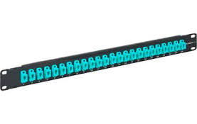
This Black box patch panel secures 12 breakout modules in the horizontal or zone distribution areas. It features a low profile that requires little wall space, as well as a large routing space for accessible patch cabling entrance. Top and bottom grommet holes provide easy entrance for the horizontal trunk cables. Incorporated spool rings can secure and store excess cable lengths with a safe bend radius.
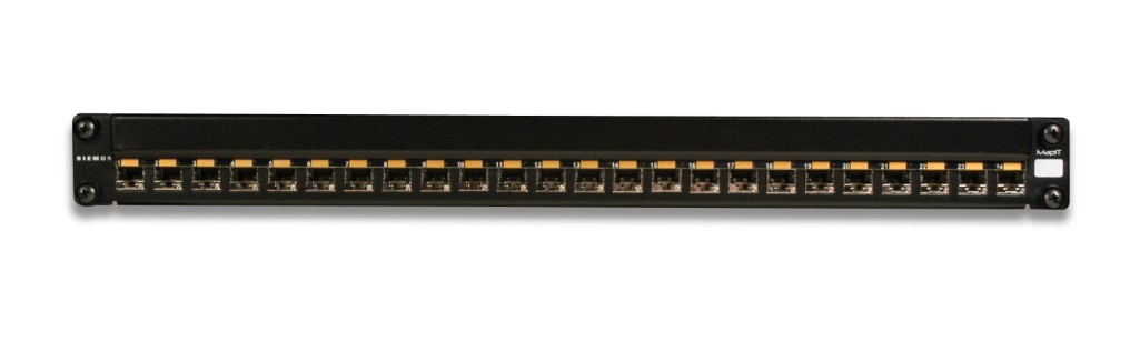
With this High Density 24 port patch panel, you can easily make one rack unit support your 10GB or higher applications. They allow you to quickly add new devices to your system without having to manually install or reconfigure other devices. The fiber is routed and connected on the inside of the cassette. There is no cutting, polishing, or terminating. These patch panels are perfect when you have high fiber count installations.
Figure 2 illustrates a typical cable layout diagram. Note that the diagram includes the cable fiber sizes (the number of strands in the fiber) to be installed, the locations for new and old pit boxes, the requirement for new conduit and for fiber optic termination cabinets.
If a fiber ring is being formed, the cables are normally cut in the pit, both ends are taken into the building where they are either spliced through or pig-tails are connected to the fibers before taken to a patch panel. Often, there is combination of spliced fibers (which are more secure compared to those on a patch panel) and fibers with pig-tails taken to a patch panel. Taking them to a patch panel allows the rings to be made or broken as required, but leaves them free to accidental removal. Compare the length of each cable run with the length of fiber optic cables on the reels that are to be used. Using this information, determine the location of any additional intermediate splicing locationg that are required.
Once the cable layout diagram is complete, a cable installation program should be drawn up. This document will be used by the contractor’s installation procedures and requirements. It should contain a thorough description of all the considerations and potential problems that were noted during the site survey.
The installation program should include a detailed description of the following information:
- The logistics of pulling the cable.
- Where the pulling equipment and cable reels should be located during the installation for each separate pull.
- The precise location where the pit boxes, termination cabinets and splicing trays are to be located.
- Which fibers are to be spliced and which fibers are to be taken through to a patch panel.
- Each separate cable pull and the cable size and type to be pulled.
- Each separate conduit installation and the size and type of conduit to be installed. Specify which conduit is to be used over each section.
- Which cable trays are to be used.
- The routes to be taken for cable runs through the roof space.
- All the cable trays, conduits or other housings that will need replacing.
- An installation schedule that would minimize traffic congestion while carrying out road works during peak hours.
- The setting up of ‘no parking’areas where installation equipment is to be located. This should be carried out the day before the installation begins. This requirement should cover all pit boxes and manholes.
- All observations that were made during the site visit.
- The specific responsibilities of each member of the installation team should be defined.
When the installation is complete, document all the changes made during the installation and produce final‘as installed’drawings. This will help to ensure that the cables have been installed correctly and that future fault finding and any system upgrades will be hassle free.