As large-scale data centers transition to faster and more scalable infrastructures and with the rapid adoption of hyperscale cloud infrastructures and services, existing 100G networks fall short in meeting current demands. As the next-generation mainstream port technology, 400G significantly increases network bandwidth, enhances link utilization, and assists operators, OTT providers, and other clients in effectively managing unprecedented data traffic growth.
To meet the demand for higher data rates, FS has been actively developing a series of 400G products, including 400G switches, optical modules, cables, and network adapters.
FS 400G Switches
The emergence of 400G data center switches has facilitated the transition from 100G to 400G in data centers, providing flexibility for building large-scale leaf and spine designs while reducing the total number of network devices. This reduction can save costs and decrease power consumption. Whether it’s the powerful N9510-64D or the versatile N9550 series, FS 400G data center switches can deliver the performance and flexibility required for today’s data-intensive applications.
Of particular note is that, as open network switches, the N8550 and N9550 series switches can enhance flexibility by freely choosing preferred operating systems. They are designed to meet customer requirements by providing comprehensive support for L3 features, SONiC and Broadcom chips, and data center functionalities. Additionally, FS offers PicOS-based open network switch operating system solutions, which provide a more flexible, programmable, and scalable network operating system (NOS) at a lower total cost of ownership (TCO).
FS 400G Transceivers
FS offers two different types of packaging for its 400G transceivers: QSFP-DD and OSFP, developed to support 400G with performance as their hallmark. Additionally, FS provides CFP2 DCO transceivers for coherent transmission at various rates (100G/200G/400G) in DWDM applications. Moreover, FS has developed InfiniBand cables and transceivers to enhance the performance of HPC networks, meeting the requirements for high bandwidth, low latency, and highly reliable connections.
FS conducts rigorous testing on its 400G optical modules using advanced analytical equipment, including TX/RX testing, temperature measurement, rate testing, and spectrometer evaluation tests, to ensure the performance and compatibility of the optical modules.
FS 400G Cables
When planning 400G Ethernet cabling or connection schemes, it’s essential to choose devices with low insertion loss and good return loss to meet the performance requirements of high-density data center links. FS offers various wiring options, including DAC/AOC cables and breakout cables. FS DAC/AOC breakout cables provide three connection types to meet high-density requirements for standard and combination connector configurations: 4x100G, 2x200G, and 8x50G. Their low insertion loss and ultra-low crosstalk effectively enhance transmission performance, while their high bend flexibility offers cost-effective solutions for short links.
FS 400G Network Adapters
FS 400G network adapters utilize the industry-leading ConnectX-7 series cards. The ConnectX-7 VPI card offers a 400Gb/s port for InfiniBand, ultra-low latency, and delivers between 330 to 3.7 billion messages per second, enabling top performance and flexibility to meet the growing demands of data center applications. In addition to all existing innovative features from previous versions, the ConnectX-7 card also provides numerous enhanced functionalities to further boost performance and scalability.
FS 400G Networking Soluitons
To maximize the utilization of the 400G product series, FS offers comprehensive 400G network solutions, such as solutions tailored for upgrading from 100G to high-density 400G data centers. These solutions provide diverse and adaptable networking options customized for cloud data centers and AI applications. They are designed to tackle the continuous increase in data center traffic and the growing need for high-bandwidth solutions in extensive 400G data center networks.
In the realm of high-speed processing and complex workloads, InfiniBand is pivotal for HPC, AI, and hyperscale clouds. This article explores FS’s 100G EDR InfiniBand solution, emphasizing the deployment of QSFP28 EDR transceivers and cables to boost network performance.
What are the InfiniBand HDR 100G Cables and Transceivers
InfiniBand EDR 100G Active AOC Cables
The NVIDIA InfiniBand MFA1A00-E001, an active optical cable based on Class 1 FDA Laser, is designed for InfiniBand 100Gb/s EDR systems. With lengths ranging from 1m to 100m, these cables offer predictable latency, consuming a max of 3.5W, and enhancing airflow in high-speed HPC environments.
InfiniBand EDR 100G Passive Copper Cables
The NVIDIA InfiniBand MCP1600-E001E30 is available in lengths of 0.5m to 3m. With four high-speed copper pairs supporting up to 25Gb/s, it offers efficient short-haul connectivity. Featuring EEPROM on each QSFP28 port, it enhances host system communication, enabling higher port bandwidth, density, and configurability while reducing power demand in data centers.
InfiniBand EDR 100G Optical Modules
The 100Gb EDR optical modules, packaged in QSFP28 form factor with LC duplex or MTP/MPO-12 connectors, are suitable for both EDR InfiniBand and 100G Ethernet. They can be categorized into QSFP28 SR4, QSEP28 PSM4, QSFP28 CWDM4, and QSFP28 LR4 based on transmission distance requirements.
100Gb InfiniBand EDR System Scenario Applications
InfiniBand has gained widespread adoption in data centers, artificial intelligence, and other domains, primarily employing the spine-leaf architecture. In data centers, transceivers and cables play a pivotal role in two key scenarios: Data Center to User and Data Center Interconnects.
Amidst the evolving landscape of 100G InfiniBand EDR, FS’s solution emerges as mature and robust. Offering high bandwidth, low latency, and reduced power consumption, it enables higher port density and configurability at a lower cost. Tailored for large-scale data centers, HPC, AI, and future network expansion, customers can choose products based on application needs, transmission distance, and deployment. FS 100G EDR InfiniBand solution meets the escalating demands of modern computational workloads.
The market’s diverse methods for calculating the optical module-to-GPU ratio lead to discrepancies due to varying network structures. The precise number of optical modules required hinges on critical factors such as network card models, switch models, and the scalable unit count.
Network Card Model
The primary models are ConnectX-6 (200Gb/s, for A100) and ConnectX-7 (400Gb/s, for H100), with the upcoming ConnectX-8 800Gb/s slated for release in 2024.
Switch Model
MQM 9700 switches (64 channels of 400Gb/s) and MQM8700 switches (40 channels of 200Gb/s) are the main types, affecting optical module needs based on transmission rates.
Number of Units (Scalable Unit)
Smaller quantities use a two-tier structure, while larger quantities employ a three-tier structure, as seen in H100 and A100 SuperPODs.
H100 SuperPOD: Each unit consists of 32 nodes (DGX H100servers) and supports a maximum of 4 units to form a cluster, using a two-layer switching architecture.
A100 SuperPOD: Each unit consists of 20 nodes (DGX A100 servers) and supports a maximum of 7 units to form a cluster. If the number of units exceeds 5, a three-layer switching architecture is required.
Optical Module Demand Under Four Network Configurations
Projected shipments of H100 and A100 GPUs in 2023 and 2024 indicate substantial optical module demands, with a significant market expansion forecasted. The following are four application scenarios:
A100+ConnectX6+MQM8700 Three-layer Network: Ratio 1:6, all using 200G optical modules.
A100+ConnectX6+MQM9700 Two-layer Network: 1:0.75 of 800G optical modules + 1:1 of 200G optical modules.
H100+ConnectX7+MQM9700 Two-layer Network: 1:1.5 of 800G optical modules + 1:1 of 400G optical modules.
H100+ConnectX8 (yet to be released)+MQM9700 Three-layer Network: Ratio 1:6, all using 800G optical modules.
For detailed calculations regarding each scenario, you can click on this article to learn more.
Conclusion
As technology progresses, the networking industry anticipates the rise of high-speed solutions like 400G multimode optical modules. FS offers optical modules from 1G to 800G, catering to evolving network demands.
Register for an FS account, select products that suit your needs, and FS will tailor an exclusive solution for you to achieve network upgrades.
As businesses upgrade their data centers, they’re transitioning from traditional 2-layer network architectures to more advanced 3-layer routing frameworks. Protocols like OSPF and BGP are increasingly used to manage connectivity and maintain network reliability. However, certain applications, especially those related to virtualization, HPC, and storage, still rely on 2-layer network connectivity due to their specific requirements.
VXLAN Overlay Network Virtualization
In today’s fast-paced digital environment, applications are evolving to transcend physical hardware and networking constraints. An ideal networking solution offers scalability, seamless migration, and robust reliability within a 2-layer framework. VXLAN tunneling technology has emerged as a key enabler, constructing a virtual 2-layer network on top of the existing 3-layer infrastructure. Control plane protocols like EVPN synchronize network states and tables, fulfilling contemporary business networking requirements.
Network virtualization divides a single physical network into distinct virtual networks, optimizing resource use across data center infrastructure. VXLAN, utilizing standard overlay tunneling encapsulation, extends the control plane using the BGP protocol for better compatibility and flexibility. VXLAN provides a larger namespace for network isolation across the 3-layer network, supporting up to 16 million networks. EVPN disseminates layer 2 MAC and layer 3 IP information, enabling communication between VNIs and supporting both centralized and distributed deployment models.
For enhanced flexibility, this project utilizes a distributed gateway setup, supporting agile execution and deployment processes. Equal-Cost Multipath (ECMP) routing and other methodologies optimize resource utilization and offer protection from single node failures.
RoCE over EVPN-VXLAN
RoCE technology facilitates efficient data transfer between servers, reducing CPU overhead and network latency. Integrating RoCE with EVPN-VXLAN enables high-throughput, low-latency network transmission in high-performance data center environments, enhancing scalability. Network virtualization divides physical resources into virtual networks tailored to distinct business needs, allowing for agile resource management and rapid service deployment.
Simplified network planning, deployment, and operations are essential for managing large-scale networks efficiently. Unnumbered BGP eliminates the need for complex IP address schemes, improving efficiency and reducing operational risks. Real-time fault detection tools like WJH provide deep network insights, enabling quick resolution of network challenges.
Conclusion
Essentially, recent advancements in data center networking focus on simplifying network design, deployment, and management. Deploying technological solutions such as Unnumbered BGP eliminates the need for complex IP address schemes, reducing setup errors and boosting productivity. Tools like WJH enable immediate fault detection, providing valuable network insights and enabling quick resolution of network issues. The evolution of data center infrastructures is moving towards distributed and interconnected multi-data center configurations, requiring faster network connections and improving overall service quality for users.
High-Performance Computing (HPC) has become a crucial tool for solving complex problems and pushing the boundaries of scientific research, artificial intelligence, and various other applications. However, efficient operation of HPC systems requires specialized infrastructure and support. HPC has emerged as an indispensable tool across various domains, capable of addressing complex challenges and driving innovation in fields such as science, meteorology, finance, healthcare, and artificial intelligence.
Understanding the importance of data centers in supporting HPC is essential, as knowing the three fundamental components—compute, storage, and networking—that constitute high-performance computing systems is crucial.
Facilities in High-Performance Computing
Intensive computations in HPC environments generate substantial heat, necessitating advanced cooling solutions. Efficient cooling prevents overheating, ensuring system stability and prolonging hardware lifespan. Supporting HPC, data centers employ cutting-edge cooling facilities, including liquid cooling systems and precision air conditioning. Moreover, data center architects explore innovative cooling technologies like immersion cooling, submerging servers in special liquids for effective heat dissipation.
Success in HPC data centers relies on a range of specialized equipment tailored to meet the unique demands of high-performance computing. Key components include data center switches, server network cards, high-speed optical modules, DAC and AOC cables, and power supplies.
The Growing Demand for Network Infrastructure in High-Performance Computing
With revolutionary technologies like 5G, big data, the Internet of Things (IoT), and artificial intelligence (AI) permeating various aspects of society, the trajectory towards an intelligent, digitized society over the next two to three decades is inevitable. Data center computing power has become a powerful driving force, shifting focus from resource scale to computational scale.
To meet the ever-growing demand for computing power, high-performance computing (HPC) has become a top priority, especially as computational cluster scales expand from the petascale to the exascale. This shift imposes increasingly higher demands on interconnect network performance, marking a clear trend of deep integration between computation and networking. HPC introduces different network performance requirements in three typical scenarios: loosely coupled computing scenarios, tightly coupled scenarios, and data-intensive computing scenarios.
In summary, high-performance computing (HPC) imposes stringent requirements on network throughput and latency. To meet these demands, the industry widely adopts Remote Direct Memory Access (RDMA) as an alternative to the TCP protocol to reduce latency and maximize CPU utilization on servers. Despite its advantages, the sensitivity of RDMA to network packet loss highlights the importance of lossless networks.
The Evolution of High-Performance Computing Networks
Traditional data center networks have historically adopted a multi-hop symmetric architecture based on Ethernet technology, relying on the TCP/IP protocol stack for transmission. However, despite over 30 years of development, Remote Direct Memory Access (RDMA) technology has gradually replaced TCP/IP, becoming the preferred protocol for HPC networks. Additionally, the choice of RDMA network layer protocols has evolved from expensive lossless networks based on the InfiniBand (IB) protocol to intelligent lossless networks based on Ethernet.
From TCP to RDMA
In traditional data centers, Ethernet technology and the TCP/IP protocol stack have been the norm for building multi-hop symmetric network architectures. However, due to two main limitations—latency issues and CPU utilization—the TCP/IP network is no longer sufficient to meet the demands of high-performance computing. To address these challenges, RDMA functionality has been introduced at the server side. RDMA is a direct memory access technology that enables data transfer directly between computer memories without involving the operating system, thus bypassing time-consuming processor operations. This approach achieves high bandwidth, low latency, and low resource utilization.
From IB to RoCE
RDMA enables direct data read and write between applications and network cards. RDMA’s zero-copy mechanism allows the receiving end to read data directly from the sending end’s memory, significantly reducing CPU burden and improving CPU efficiency. Currently, there are three choices for RDMA network layer protocols: InfiniBand, iWARP (Internet Wide Area RDMA Protocol), and RoCE (RDMA over Converged Ethernet). Although RoCE offers many advantages, its sensitivity to packet loss requires support from lossless Ethernet. This evolution of HPC networks reflects a continuous pursuit of enhanced performance, efficiency, and interoperability.
Enterprise Innovative Solution: Designing High-Performance Data Center Networks
The architecture of data center networks has evolved from the traditional core-aggregation-access model to the modern Spine-Leaf design. This approach fully utilizes network interconnection bandwidth, reduces multi-layer convergence rates, and is easy to scale. When traffic bottlenecks occur, horizontal expansion can be achieved by increasing uplink links and reducing convergence ratios, minimizing the impact on bandwidth expansion. Overlay networks utilize EVPN-VXLAN technology to achieve flexible network deployment and resource allocation.
This solution draws on the design experience of internet data center networks, adopting the Spine-Leaf architecture and EVPN-VXLAN technology to provide a versatile and scalable network infrastructure for upper-layer services. Production and office networks are isolated by domain firewalls and connected to office buildings, labs, and regional center exits. The core switches of the production network provide up to 1.6Tb/s of inter-POD communication bandwidth and 160G of high-speed network egress capacity, with each POD’s internal horizontal network capacity reaching 24Tb, ensuring minimal packet loss. The building wiring is planned based on the Spine-Leaf architecture, with each POD’s switches interconnected using 100G links and deployed in TOR mode. The overall network structure is more streamlined, improving cable deployment and management efficiency.
Future-Oriented Equipment Selection
When envisioning and building data center networks, careful consideration of technological advancements, industry trends, and operational costs over the next five years is crucial. The choice of network switches plays a vital role in the overall design of data center networks. Traditional large-scale network designs often opt for chassis-based equipment to enhance the overall capacity of the network system, but scalability is limited.
Therefore, for the network equipment selection of this project, NVIDIA strongly advocates for adopting a modular switch network architecture. This strategic approach facilitates rapid familiarization by maintenance teams. Additionally, it provides operational flexibility for future network architecture adjustments, equipment reuse, and maintenance replacements.
In response to the ongoing trend of business transformation and the surge in demand for big data, most data center network designs adopt the mature Spine-Leaf architecture, coupled with EVPN-VXLAN technology to achieve efficient network virtualization. This architectural approach ensures convenient high-bandwidth, low-latency network traffic, laying the foundation for scalability and flexibility.
How FS Can Help
FS is a professional provider of communication and high-speed network system solutions for network, data center, and telecommunications customers. Leveraging NVIDIA® InfiniBand switches, 100G/200G/400G/800G InfiniBand transceivers, and NVIDIA® InfiniBand adapters, FS offers customers a comprehensive set of solutions based on InfiniBand and lossless Ethernet (RoCE). These solutions meet diverse application requirements, enabling users to accelerate their businesses and enhance performance. For more information, please visit FS.COM.
From Transformers to the widespread adoption of ChatGPT in 2023, people have come to realize that increasing model parameters can enhance performance, aligning with the scaling law of parameters and performance. Particularly, when the parameter scale exceeds trillions, the language comprehension, logical reasoning, and problem-solving capabilities of large AI models improve rapidly.
To meet the demands of efficient distributed computing in large-scale training clusters, the training process of AI models typically involves various parallel computing modes such as data parallelism, pipeline parallelism, and tensor parallelism. In these parallel modes, collective communication operations among multiple computing devices become crucial. Therefore, designing efficient cluster networking schemes in large-scale training clusters of AI models is key to reducing communication overhead and improving the effective computation-to-communication time ratio of GPUs.
Challenges in Scaling GPU Networks for Efficient Training of Ultra-Large AI Models
The computing demands of artificial intelligence applications are experiencing exponential growth, with model sizes continuously expanding, necessitating significant computational power and high memory requirements. Appropriate parallelization methods such as data, pipeline, and tensor parallelism have become key to improving training efficiency. Training extra-large models requires clusters containing thousands of GPUs, utilizing high-performance GPUs and RDMA protocols to achieve throughputs of 100 to 400 Gbps. Specifically, achieving high-performance interconnection among thousands of GPUs poses several challenges in terms of network scalability:
Challenges encountered in large-scale RDMA networks, such as head-of-line blocking and PFC deadlock storms.
Network performance optimization, including more effective congestion control and load balancing techniques.
Issues with NIC connectivity, as individual hosts are subject to hardware performance limitations. Addressing how to establish thousands of RDMA QP connections.
Selection of network topology, considering whether to adopt traditional Fat Tree structures or reference high-performance computing network topologies like Torus or Dragonfly.
Optimizing GPU Communication for Efficient AI Model Training Across Machines
In AI large-scale model training, GPU communication within and across machines generates significant data. With billions of model parameters, communication from parallelism can reach hundreds of GB. Efficient completion relies on GPU communication bandwidth within machines. GPUs should support high-speed protocols to reduce CPU memory copying. PCIe bus bandwidth determines if network card bandwidth is fully utilized. For example, with PCIe 3.0 (16 lanes = 16GB/s), if inter-machine communication has 200Gbps bandwidth, network performance may not be fully utilized.
Crucial Factors in AI Large-Scale Model Training Efficiency
In data communication, network latency comprises two components: static latency and dynamic latency. Static latency includes data serialization, device forwarding, and electro-optical transmission delays, determined by the forwarding chip’s capacity and transmission distance, representing a constant value when network topology and data volume are fixed. In contrast, dynamic latency significantly affects network performance, including queuing delays within switches and delays caused by packet loss and retransmission typically due to network congestion. Besides latency, network fluctuations introduce latency jitter, affecting training efficiency.
Critical for Computational Power in Large-Scale AI Model Training
Cluster computing power is crucial for AI model training speed. Network system reliability forms the foundation of cluster stability. Network failures disrupt computing node connections, impairing overall computing capability. Performance fluctuations may decrease resource utilization. Fault-tolerant replacement or elastic expansion may be necessary to address failed nodes during training tasks. Additionally, unexpected network failures can lead to communication library timeouts, severely impacting efficiency. Therefore, obtaining detailed throughput, packet loss, and other information is vital for fault detection.
The Role of Automated Deployment and Fault Detection in Large-Scale AI Clusters
The establishment of intelligent lossless networks often relies on RDMA protocols and congestion control mechanisms, accompanied by a variety of complex configurations. Any misconfiguration of these parameters can potentially impact network performance and lead to unforeseen issues. Therefore, efficient and automated deployment can effectively enhance the reliability and efficiency of large-scale model cluster systems.
Similarly, in complex architectural and configuration scenarios, timely and accurate fault localization during business operations is crucial for ensuring overall business efficiency. Automated fault detection aids in quickly identifying issues, notifying management accurately, and reducing costs associated with issue identification. It can swiftly identify root causes and provide corresponding solutions.
Large-scale AI models have specific requirements in terms of scale, bandwidth, stability, latency/jitter, and automation capabilities. However, there still exists a technological gap in current data center network configurations to fully meet these requirements.
Al Intelligent Computing Center Network Architecture Design Practice
Traditional cloud data center networks prioritize north-south traffic, leading to congestion, high latency, and bandwidth constraints for east-west traffic. For intelligent computing scenarios, it’s recommended to build dedicated high-performance networks to accommodate workloads, meeting high-bandwidth, low-latency, and lossless requirements.
Based on current mature commercial switches, it is recommended to consider different models of InfiniBand/RoCE switches and the supported GPU scale to set the following specifications for physical network architecture:
Standard: Based on InfiniBand HDR switches, a dual-layer Fat-Tree network architecture supports up to 800 GPU cards per cluster.
Large-scale: Based on 128-port 100G Ethernet switches, a RoCE dual-layer Fat-Tree network architecture supports up to 8192 GPU cards per cluster.
Extra-large: Based on InfiniBand HDR switches, an InfiniBand three-layer Fat-Tree network architecture supports up to 16000 GPU cards per cluster.
Extra-extra-large: Based on InfiniBand Quantum-2 switches or equivalent Ethernet data center switches, adopting a three-layer Fat-Tree network architecture supports up to 100000 GPU cards per cluster.
In addition, high-speed network connections are crucial for ensuring efficient data transmission and processing.
How FS Can Help
FS provides high-quality connectivity products to meet the demands of AI model network deployment. The FS product portfolio includes (200G, 400G) InfiniBand switches, data center switches (10G, 40G, 100G, 400G) network cards, and (10/25G, 40G, 50/56G, 100G) optical modules, accelerating AI model training and inference processes. Optical modules offer high bandwidth, low latency, and low error rates, enhancing data center network capabilities for faster and more efficient AI computing. For more information, please visit the FS website.
The emergence of AI applications and large-scale models (such as ChatGPT) has made computing power an indispensable infrastructure for the AI industry. With the ever-increasing demand for swifter communication in supercomputing, 800G high-speed optical modules have evolved into a crucial component of artificial intelligence servers. Here are some key reasons why the industry is progressively favoring 800G optical transceiver and solutions.
Bandwidth-Intensive AI Workloads
In artificial intelligence computing applications, especially those involving deep learning and neural networks, a significant amount of data is generated that needs to be transmitted over the network. Research indicates that the higher capacity of 800G transceivers helps meet the bandwidth requirements of these intensive workloads.
Data Center Interconnect
With the prevalence of cloud computing, the need for efficient connections within data centers becomes crucial. The 800G optical transceiver enable faster and more reliable connections between data centers, facilitating seamless data exchange and reducing latency.
Transition to Spine-Leaf Architecture
As east-west traffic experiences rapid growth within data centers, the traditional three-tier architecture is encountering progressively challenging tasks and heightened performance demands. The adoption of 800G optical transceiver has propelled the emergence of a Spine-Leaf network architecture, offering multiple advantages such as high bandwidth utilization, outstanding scalability, predictable network latency, and enhanced security.
Future-Proofing Networks
With the exponential growth in the volume of data processed by artificial intelligence applications, choosing to invest in 800G optical transceivers ensures that the network can meet the continuously growing data demands, providing future-oriented assurance for the infrastructure.
Conclusion
The adoption of 800G optical transceiver offers a forward-looking solution to meet the ongoing growth in data processing and transmission. Indeed, the collaborative interaction between artificial intelligence computing and high-speed optical communication will play a crucial role in shaping the future of information technology infrastructure.
How FS Can Help
The profound impact of artificial intelligence on data center networks highlights the critical role of 800G optical transceivers. Ready to elevate your network experience? As a reliable network solution provider, FS provides a complete 800G product portfolio designed for global hyperscale cloud data centers. Seize the opportunity – register now for enhanced connectivity or apply for a personalized high-speed solution design consultation.
Explore the vast potential of 800G optical modules in the AI era in the following article:
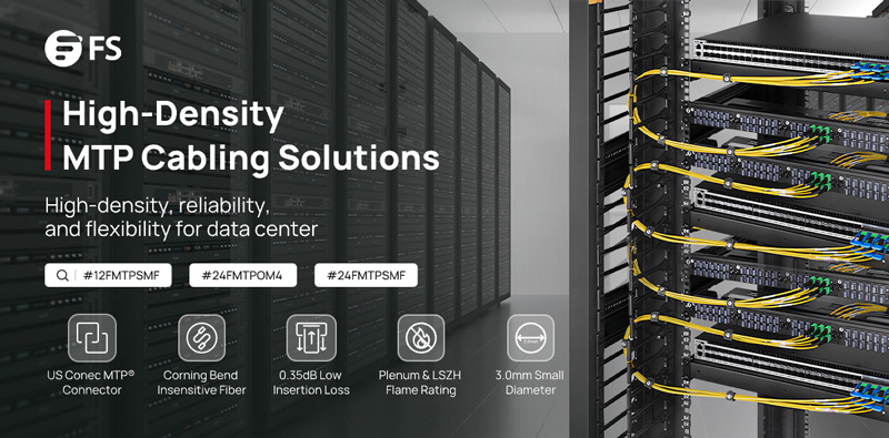
In the era of ultra-high-speed data transmission, MTP/MPO cables have become a key player, especially in the context of 800G networks. In essence, MTP/MPO cables emerge as catalysts for the evolution toward 800G networks, offering a harmonious blend of high-density connectivity, reliability, and scalability. This article will delve into the advantages of MTP/MPO cables in 800G networks and provide specific solutions for constructing an 800G network, offering valuable insights for upgrading your existing data center.
Challenges Faced in 800G Data Transmission
As a critical hub for storing and processing vast amounts of data, data centers require high-speed and stable networks to support data transmission and processing. The 800G network achieves a data transfer rate of 800 Gigabits per second (Gbps) and can meet the demands of large-scale data transmission and processing in data centers, enhancing overall efficiency.
Therefore, many major internet companies are either constructing new 800G data centers or upgrading existing data centers from 100G, 400G to 800G speeds. However, the pursuit of 800G data transmission faces numerous complex challenges that necessitate innovative solutions. Here, we analyze the intricate obstacles associated with achieving ultra-fast data transmission.
Insufficient Bandwidth & High Latency
The 800G network demands extensive data transmission, placing higher requirements on bandwidth. It necessitates network equipment capable of supporting greater data throughput, particularly in terms of connection cables. Ordinary optical fibers typically consist of a single fiber within a cable, and their optical and physical characteristics are inadequate for handling massive data, failing to meet the high-bandwidth requirements of 800G.
While emphasizing high bandwidth, data center networks also require low latency to meet end-user experience standards. In high-speed networks, ordinary optical fibers undergo more refraction and scattering, resulting in additional time delays during signal transmission.
Limited Spatial Layout
The high bandwidth requirements of 800G networks typically come with more connection ports and optical fibers. However, the limited space in data centers or server rooms poses a challenge. Achieving high-density connections requires accommodating more connection devices in the constrained space, leading to crowded layouts and increased challenges in space management and design.
Complex Network Architecture
The transition to an 800G network necessitates a reassessment of network architecture. Upgrading to higher data rates requires consideration of network design, scalability, and compatibility with existing infrastructure. Therefore, the cabling system must meet both current usage requirements and align with future development trends. Given the long usage lifecycle of cabling systems, addressing how to match the cabling installation with multiple IT equipment update cycles becomes a challenging problem.
High Construction Cost
Implementing 800G data transmission involves investments in infrastructure and equipment. Achieving higher data rates requires upgrading and replacing existing network equipment and cabling management patterns, incurring significant costs. Cables, in particular, carry various network devices, and their required lifecycle is longer than that of network equipment. Frequent replacements can result in resource wastage.
Effectively addressing these challenges is crucial to unlocking the full potential of a super-fast, efficient data network.
The significance of MTP/MPO cables in high-speed networks, especially in 800G networks, lies in their ability to manage the escalating data traffic efficiently. The following are key advantages of MTP/MPO cables:
High Density, High Bandwidth
MTP/MPO cables adopt a high-density multi-fiber design, enabling the transmission of multiple fibers within a relatively small connector. This design not only provides ample bandwidth support for data centers, meeting the high bandwidth requirements of an 800G network, but also helps save space and supports the high-density connection needs for large-scale data transfers.
Additionally, MTP/MPO cables exhibit excellent optical and mechanical performance, resulting in low insertion loss in high-speed network environments. By utilizing a low-loss cabling solution, they effectively contribute to reducing latency in the network.
Flexibility and Scalability
MTP/MPO connectors come in various configurations, accommodating different fiber counts (8-core, 12-core, 16-core, 24-core, etc.), supporting both multimode and single-mode fibers. With trunk and breakout designs, support for different polarities, and male/female connector options, these features allow seamless integration into various network architectures. The flexibility and scalability of MTP/MPO connectors enable them to adapt to evolving network requirements and facilitate future expansions, particularly in the context of 800G networks.
Efficient Maintenance
The high-density and compact design of MTP/MPO cables contribute to saving rack and data room space, enabling data centers to utilize limited space resources more efficiently. This, in turn, facilitates the straightforward deployment and reliable operation of 800G networks, reducing the risks associated with infrastructure changes or additions in terms of cost and performance. Additionally, MTP/MPO cables featuring a Plenum (OFNP) outer sheath exhibit fire resistance and low smoke characteristics, minimizing potential damage and saving on cabling costs.
Scaling the 800G Networks With MTP/MPO Cables
In the implementation of 800G data transmission, the wiring solution is crucial. MTP/MPO cables, as a key component, provide reliable support for high-speed data transmission. FS provides professional solutions for large-scale data center users who require a comprehensive upgrade to 800G speeds. Aim to rapidly increase data center network bandwidth to meet the growing demands of business.
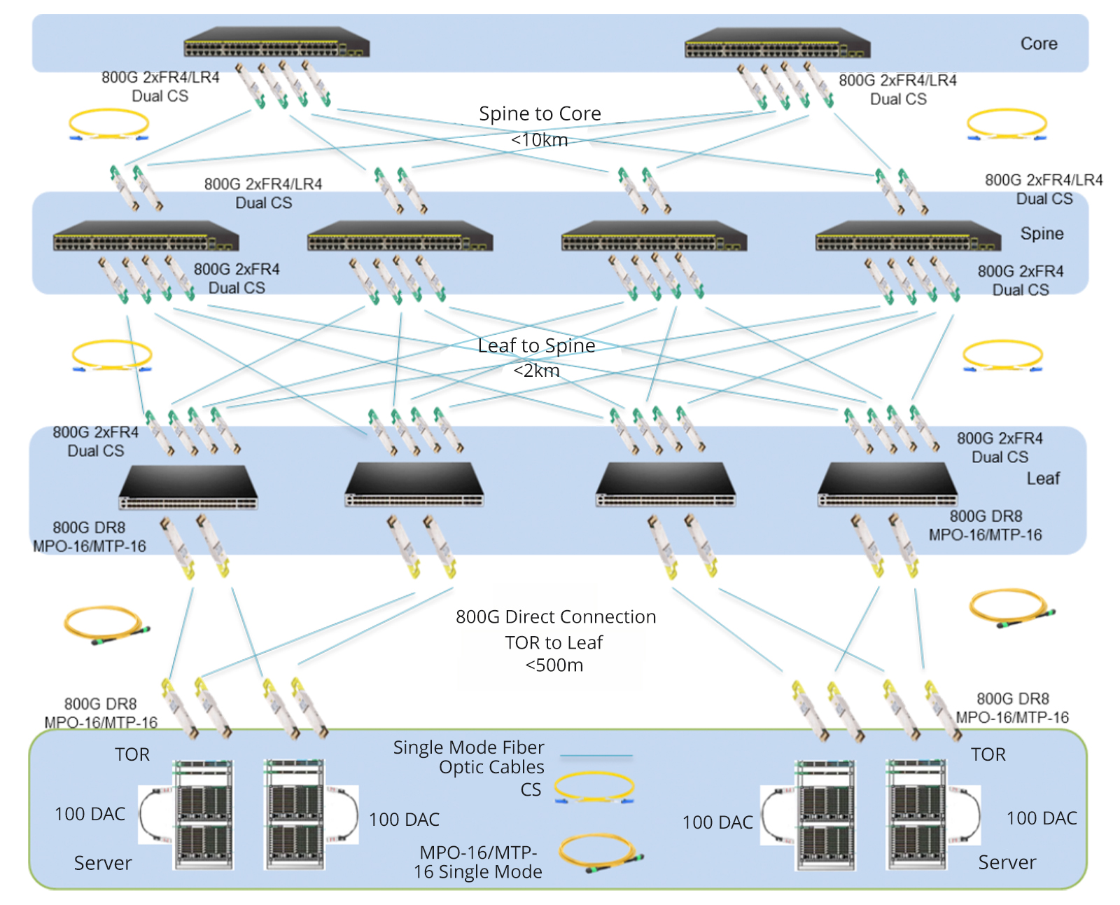
Newly Built 800G Data Center
Given the rapid expansion of business, many large-scale internet companies choose to build new 800G data centers to enhance their network bandwidth. In these data centers, all network equipment utilizes 800G switches, combined with MTP/MPO cables to achieve a direct-connected 800G network. To ensure high-speed data transmission, advanced 800G 2xFR4/2xLR4 modules are employed between the core switches and backbone switches, and 800G DR8 modules seamlessly interconnect leaf switches with TOR switches.
To simplify connections, a strategic deployment of the 16-core MTP/MPO OS2 trunk cables directly connects to 800G optical modules. This strategic approach maximally conserves fiber resources, optimizes wiring space, and facilitates cable management, providing a more efficient and cost-effective cabling solution for the infrastructure of 800G networks.
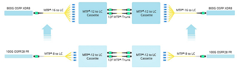
Upgrade from 100G to 800G
Certainly, many businesses choose to renovate and upgrade their existing data center networks. In the scenario below, engineers replaced the original 8-core MTP/MPO-LC breakout cable with the 16-core version, connecting it to the existing MTP cassettes. The modules on both ends, previously 100G QSFP28 FR, were upgraded to 800G OSFP XDR8. This seamless deployment migrated the existing structured cabling to an 800G rate. It is primarily due to the 16-core MTP/MPO-LC breakout cable, proven as the optimal choice for direct connections from 800G OSFP XDR8 to 100G QSFP28 FR or from 800G QSFP-DD/OSFP DR8 to 100G QSFP28 DR.
In short, this solution aims to increase the density of fiber optic connections in the data center and optimize cabling space. Not only improves current network performance but also takes into account future network expansion.
Elevating from 400G to the 800G Network
How to upgrade an existing 400G network to 800G in data centers? Let’s explore the best practices through MTP/MPO cables to achieve this goal.
Based on the original 400G network, the core, backbone, and leaf switches have all been upgraded to an 800G rate, while the TOR (Top of Rack) remains at a 400G rate. The core and backbone switches utilize 800G 2xFR4/2xLR4 modules, the leaf switches use 800G DR8 modules, and the TOR adopts 400G DR4 modules. Deploying two 12-core MTP/MPO OS2 trunk cables in a breakout configuration between the 400G and 800G optical modules facilitates interconnection.
This cabling solution enhances scalability, prevents network bottlenecks, reduces latency, and is conducive to expanding bandwidth when transitioning from lower-speed to higher-speed networks in the future. Additionally, this deployment retains the existing network equipment, significantly lowering cost expenditures.
Ultimately, the diverse range of MTP/MPO cable types provides tailored solutions for different connectivity scenarios in 800G networks. As organizations navigate the complexities of high-speed data transmission, MTP/MPO cables stand as indispensable enablers, paving the way for a new era of efficient and robust network infrastructures.
How FS Can Help
The comprehensive networking solutions and product offerings not only save costs but also reduce power consumption, delivering higher value. Considering an upgrade to 800G for your data center network? FS tailors customized solutions for you. Don’t wait any longer—Register as an FS website member now and enjoy free technical support.
When designing a new network architecture based on 10GB Ethernet, we face the challenge of choosing the right equipment to achieve maximum performance and support the future demands of complex network applications.
There are two options for 10Gb Ethernet interconnection: 10GBASE-T and SFP+ solutions (SFP+ and DAC/AOC). 10GBASE-T copper cable modules can span network links of up to 100 meters using cat 6a/cat 7 cables. SFP+ optical devices will support distances of up to 300 meters on multimode fiber and up to 80 kilometers on single-mode fiber.
What are the differences?
SFP+ fiber offers lower latency and cost, and the power consumption of SFP+ solutions is also significantly lower, with the power consumption of 10GBASE-T being approximately three to four times that of the SFP+ solution. Moreover, 1Gb SFP transceivers can be inserted into SFP+ ports, functioning at a speed of 1Gb and linking through optical cables to conventional ports. They can also be plugged into SFP modules that are compatible with 1GBase-T, establishing connections at lower speeds with traditional ports.
However, 10GBASE-T copper cabling provides effective backward compatibility with standard copper network equipment, making optimal use of existing copper infrastructure wiring. Additionally, 10GBASE-T is backward compatible with 1G ports, and many low-bandwidth devices still use 1G ports. Compared to SFP+ solutions for small enterprises, 10GBASE-T is generally more cost-effective and easier to deploy.
Conclusion
In comparison, if scalability and flexibility are crucial for small enterprise applications, then 10GBASE-T cabling is the better choice. However, if power efficiency and lower latency are paramount, then 10G SFP+ cabling is clearly the winner.
Whether it’s a 10G copper cabling solution or a 10G fiber cabling solution, FS can customize it according to your needs. Click to register now and promptly enjoy your exclusive solution design.
Optical fiber communication technology is crucial for efficient information transmission, significantly enhancing data transmission speeds. Optical modules, a vital component of this technology, play a key role. Among the parameters associated with optical modules, common ones include SFP-10G-SR and SFP-10G-LR. When making a purchase decision, it’s pivotal for you to understand the difference between SFP-10G-SR and SFP-10G-LR before choosing products.
What are the SFP-10G-SR and SFP-10G-LR
SFP refers to hot-pluggable small form factor modules. 10G represents its maximum transmission rate of 10.3 Gbps, which is suitable for 10 Gigabit Ethernet. SR and LR represent the transmission distance of the SFP 10g module.
SFP-10G-SR
SFP-10G-SR is designed for short-distance transmission, typically up to 300 meters over multimode fiber. Using 850 nm wavelength laser and LC bidirectional connector, it is easy to plug and install. The module supports hot-swappable function, which can be safely replaced while the device is running, with stable performance and reliability. In data center networks, SFP-10G-SR is often used for connections between servers to support high-speed data transmission. It is also suitable for enterprise network environments, especially in scenarios with high network performance requirements.
SFP-10G-LR
The SFP-10G-LR is specifically engineered for medium to long-distance transmissions, typically spanning 10 to 40 kilometers over single-mode fiber. Boasting a 1310nm wavelength laser and an LC bidirectional connector, it facilitates effortless and smooth installation. The compatibility of SFP-10G-LR with single-mode optical fiber makes it an ideal solution for fulfilling communication needs in medium to long-distance scenarios, including establishing connections between remote offices. Furthermore, it proves well-suited for constructing network backbones, enabling high-speed data transmission among diverse network devices.
Differences Between SFP-10G-SR and SFP-10G-LR
Transmission Distance: The primary distinction lies in their coverage range, with SFP-10G-SR for short distances and SFP-10G-LR for longer ones.
Fiber Compatibility: SFP-10G-SR works with multimode fiber, while SFP-10G-LR requires single-mode fiber.
Use Cases: SFP-10G-SR is optimal for intra-building connections, while SFP-10G-LR is suitable for inter-building or even metropolitan-area connections.
Wavelength: The SFP-10G-SR uses a laser with a wavelength of 850 nanometers, while the SFP-10G-LR uses a laser with a wavelength of 1310 nanometers.
How to Choose the Right Module
After understanding the difference between SFP-10G-SR and SFP-10G-LR, we will start from typical application scenarios, combining them with your network requirements, to provide guidance on selecting the appropriate SFP 10G optical module for you.
Data Center
When linking servers, storage devices, or network components within the data center, opt for SFP-10G-SR for short-distance connections like in-rack setups. For cross-rack connectivity, SFP-10G-LR is the best choice.
Intra-Enterprise Network
Establishing high-speed connections within the enterprise, such as inter-floor or inter-department links, demands tailored choices. For shorter intra-floor connections, select SFP-10G-SR. Opt for SFP-10G-LR when spanning different floors.
Remote Office/Branch Office
For network connections linking remote or branch offices with the headquarters, SFP-10G-LR is the preferred module due to its suitability for longer distances, ensuring coverage for remote locations.
Inter-City Data Transmission
When establishing high-speed data connections between cities, the preferred choice is SFP-10G-LR, thanks to its compatibility with longer fiber distances, addressing the needs of inter-city connections.
Budget Constraints
If facing budget limitations and the connection distance permits, SFP-10G-SR is generally the more economical option.
Unlocking the Potential of the SFP 10g module with FS Products
The burgeoning era of digitization has spurred a growing demand for optical modules across various sectors, including enterprise networks, data centers, campus networks, and metropolitan area networks. Building on the diverse applications of optical modules, as a premier network solutions provider, FS.COM offers a diverse range of hot-swappable SFP 10G modules designed to maximize uptime and streamline serviceability. Equipped with Digital Optical Monitoring (DDM) capabilities, each unit is meticulously customized and coded for full-function compatibility. FS products undergo rigorous testing and verification to ensure the seamless and reliable operation of your network.
The following table sorts out the products of these two models (SFP-10G-SR and SFP-10G-LR) on the FS. You can choose the most suitable one according to your needs.
Model
SFP-10G-SR
SFP-10G-LR
Data Rate (Max)
10.3125Gbps
10.3125Gbps
Wavelength
850nm
1310nm
Cable Distance (Max)
300m@OM3400m@OM4
10km
Connector
Duplex LC
Duplex LC
Transmitter Type
VCSEL
DFB
Cable Type
MMF
SMF
TX Power
-7.3~-1dBm
-8.2~0.5dBm
Receiver Sensitivity
< -11.1dBm
<-14.4dBm
Power Consumption
<1W
≤1W
Operating Temperature
0 to 70°C (32 to 158°F)
0 to 70°C (32 to 158°F)
Application Range
Only used for short distance connections
Only used for long distance connections
Conclusion
In short, which product to choose ultimately depends on your network layout and connectivity needs. The above considerations can help you quickly select the right product to achieve the best performance in your specific network environment. If you would like to learn about other types of SFP 10g modules, you can visit the following resources for more information.


-18.jpg)
-17.jpg)