Fiberstore Passive Optical Components Solution

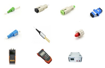
Passive optical components market is propelled by the accelerating bandwidth requirements coupled with the growth of passive optical network (PON). Usage of passive optical components to obtain energy efficient network solutions is gaining popularity. This article will introduce some Fiberstore passive optical components.

Optical Attenuators: an optical attenuator is a device that is used to reduce the power level of an optical signal. Optical attenuators are commonly used in fiber optic communications, either to test power level margins by temporarily adding a calibrated amount of signal loss, or installed permanently to properly match transmitter and receiver levels.

optical attenuators

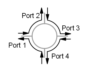
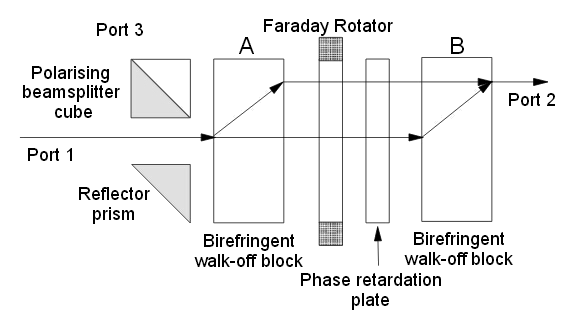
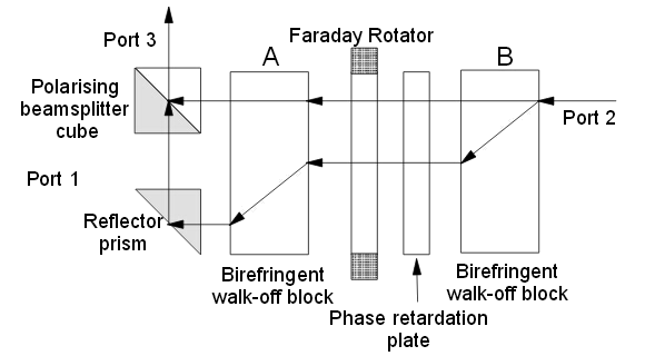
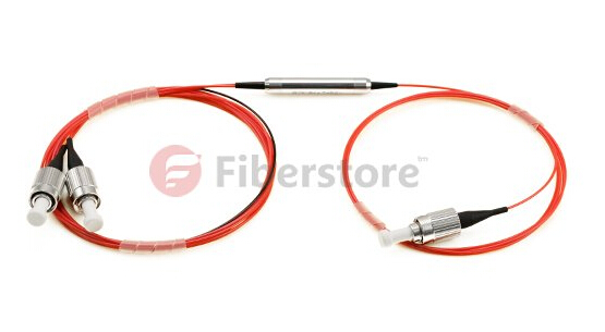
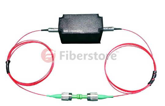
Optical Circulator: an optical circulator is a multi-port (minimum three ports) non-reciprocal passive component. The function of an optical circulator is similar to that of a microwave circulator — to transmit a light wave from one port to the next sequential port with a maximum intensity, but at the same time to block any light transmission from one port to the previous port.

optical circulator

Fiber Collimator: a fiber collimator is a device for collimating the light coming from a fiber, or for launching collimated light into the fiber. It is used to expand and collimate the output light at the fiber end, or to couple light beams between two fibers. Both single-mode fiber collimators and multimode fiber collimators are available.

fiber collimator

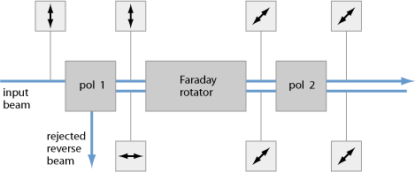
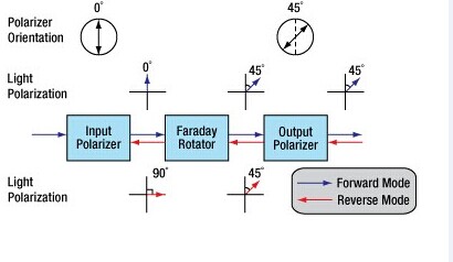
Optical Isolator: an optical isolator is a passive optical component that allows light to propagate in only one direction. Optical isolators are typically used to protect light sources from back reflections or signals that can cause instabilities and damage. The operation of optical isolators depends on the Faraday effect, which is used in the main component, the Faraday rotator.

optical isolator

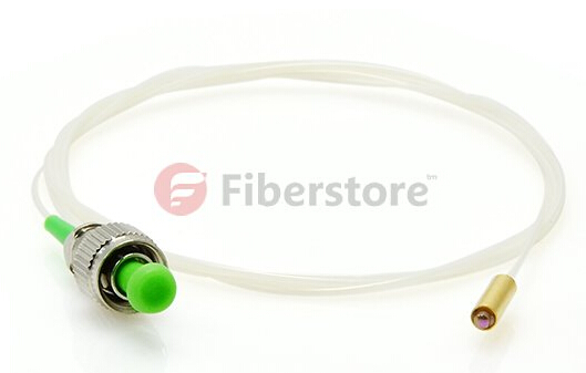
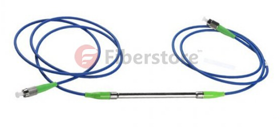
Fiber Optic Sensor: a fiber optic sensor is a sensor that uses optical fiber either as the sensing element (intrinsic sensors), or as a means of relaying signals from a remote sensor to the electronics that process the signals (extrinsic sensors). Fiber optic sensors are immune to electromagnetic interference, and do not conduct electricity so they can be used in places where there is high voltage electricity or flammable material such as jet fuel.

fiber optic sensor

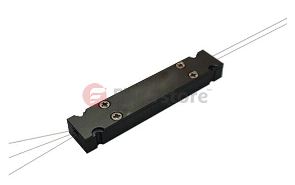
Pump Combiner: a pump combiner is a passive optical component built based on fused biconical taper (FBT) technique. Pump combiners are widely used in fiber laser, fiber amplifier, high power EDFA, biomedical and sensor system etc. Three types of pump combiners are available: Nx1 Multimode Pump Combiner, (N+1)x1 Multimode Pump and Signal Combiner, PM(N+1)x1 PM Pump and Signal Combiner.

pump combiner

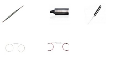
Polarization Components: polarization is the state of the e-vector orientation. Polarization components are used to isolate and transmit a single state of polarized light while absorbing, reflecting, and deviating light with the orthogonal state of polarization. Polarization components can be utilized in high power optical amplifiers and optical transmission system, test and measurement.

polarization components

Fiberstore has all of the above passive optical components with high quality and reasonable price. You can select excellent passive optical components or other optical products for your network at www.fs.com.

Polarization Dependent Isolator VS. Polarization Independent Isolator

Connectors and other types of optical devices on the output of the transmitter may cause reflection, absorption, or scattering of the optical signal. These effects on the light beam may cause light energy to be reflected back at the source and interfere with source operation. In order to reduce the effects of the interference, an optical isolator is usually used. Optical isolator allows a beam of light to stream through a single one way direction. At the same time, it prevents the light from going back in the opposite direction. According to the polarization characteristics, optical isolators can be divided into two types, including polarization dependent isolator and polarization independent isolator. The polarizer-based module makes a polarization dependent isolator, and the birefringent crystal-based structure makes a polarization independent isolator. You may be very confused about them as you find that there is only a little difference via their names. So, what are they and what are the differences between them? This paper will give you the answer.

Polarization Dependent Isolator

The polarization dependent isolator consists of three parts, an input polarizer , a Faraday rotator, and an output polarizer. Light traveling in the forward direction becomes polarized vertically by the input polarizer. The Faraday rotator will rotate the polarization by 45°. The analyser then enables the light to be transmitted through the isolator. Light traveling in the backward direction becomes polarized at 45° by the analyser. The Faraday rotator will again rotate the polarization by 45°. This means the light is polarized horizontally. Since the polarizer is vertically aligned, the light will be extinguished.

principle of polarization dependent isolator

The picture shows us a Faraday rotator with an input polarizer, and an output analyser. For a polarization dependent isolator, the angle between the polarizer and the analyser, is set to 45°. The Faraday rotator is chosen to give a 45° rotation. Because the polarization of the source is typically maintained by the system, polarization dependent isolator is widely used in free space optical systems.

Polarization Independent Isolator

The polarization independent isolator also consists of three parts, an input birefringent wedge, a Faraday rotator, and an output birefringent wedge. Light traveling in the forward direction is split by the input birefringent wedge into its vertical (0°) and horizontal (90°) components, called the ordinary ray (o-ray) and the extraordinary ray (e-ray) respectively. The Faraday rotator rotates both the o-ray and e-ray by 45°. This means the o-ray is now at 45°, and the e-ray is at −45°. The output birefringent wedge then recombines the two components.

principle of polarization independent isolator

Light traveling in the backward direction is separated into the o-ray at 45, and the e-ray at −45° by the birefringent wedge. The Faraday Rotator again rotates both the rays by 45°. Now the o-ray is at 90°, and the e-ray is at 0°. Instead of being focused by the second birefringent wedge, the rays diverge. The picture shows the propagation of light through a polarization independent isolator. While polarization dependent isolator allows only the light polarized in a specific direction, polarization independent isolator transmit all polarized light. So it is usually widely used in optical fiber amplifier.

Comparison of Polarization Dependent Isolator and Polarization Independent Isolator

In fact, you have already understood these two types of isolators according to the contents above. We can see their similarities and differences through the comparison of their definition, working principle and applications. Both of them consist of three parts and have a same principle based on Faraday effect. However, to overcome the limitation of polarization dependent isolator, polarization independent isolator has been developed. Regardless of the polarization state of the input beam, the beam will propagate through the isolator to the output fiber and the reflected beam will be isolated from the optical source. If the extinction ratio is important, a polarization dependent isolator should be used with either polarization maintaining fibers or even regular single-mode fibers. If the system has no polarization dependence, a polarization independent isolator will be the obvious choice.

Passive Optical Components — Optical Circulator

Optical Circulators are microoptic devices and can be made with any number of ports but 3 and 4 port versions are most common. Also, it is common to build an asymmetric version where the last port does not circulate around to the first. While this saves some cost this is not the most important reason for doing it. If we make sure the last port does not circulate around to the first, we can use the device in systems where we do not need (or want) this feature. For example, if the input to the first port is directly connected to a laser we certainly don’t want spurious signals to be returned back into it.

One of the great attractions of optical circulators is the relatively low level of loss. Typical devices give a port-to-port loss of between 0.5 dB and 1.5 dB. Optical circulators are very versatile devices and may be used in many applications. For example, a bidirectional link consisting of two fiber strands (one for each direction) is multiplexed onto a single strand of fiber. This might be done to save the cost of fiber. Of course if you did something like this you would need to take particular care to minimise reflections on the link.

Operating Principle

By itself there is no single, simple principle behind the optical circulator. Optical circulators are made of an assembly of optical components. There are many different designs but the key principle is like that of the optical isolator. The basic function of a circulator is illustrated in the figure below. Light entering at any particular port travels around the circulator and exits at the next port. Light entering at port 1 leaves at port 2, entering at port 2 leaves at port 3 and so on. The device is symmetric in operation around a circle.

4-Port Optical Circulator

Light travelling in one direction through a Faraday rotator has its polarisation rotated in one particular direction. Light entering the Faraday rotator from the opposite direction has its phase rotated in the opposite direction (relative to the direction of propagation of the light). Another way of looking at this is to say that light is always rotated in the same direction in relation to the rotator regardless of its direction of travel. This is complicated by the presence of unpredictable polarisation. We could filter the unwanted polarisation out but we would lose (on average) half our light in doing that—and often a lot more. So we separate the incident “ray” into two orthogonally polarised rays and treat each polarisation separately. The two halves of the ray are then re-combined before being output to the destination port.

Here is a figure showing a basic 3-port optical circulator. Its components function as following:

  • Polarising Beam Splitter Cube: This device separates the input ray into two orthogonally polarised rays.
  • Birefringent “Walk-off” Block: This is just a block of birefringent material cut at 45° to the optic axis. A ray incident at a normal to the air-crystal interface is split into two rays of orthogonal polarisation. The ordinary ray is not refracted and passes through unaffected. The extraordinary ray is refracted at an angle to the normal.
  • Faraday Rotator and Phase Plate: This combination passes light in one direction completely unchanged! (In the figure this is the right-to-left direction.) In the opposite direction polarisation of incoming light is rotated by 90°. In the left-to-right direction the Faraday rotator imparts a phase rotation of 45° (clockwise) and the phase plate rotates the light another 45° (also clockwise). Thus we get a net 90° clockwise rotation. In the right-to-left direction the phase plate rotates the light in the same direction (in relation to the direction of the ray of light) as before, that is, anti-clockwise at 45°. The Faraday rotator however rotates the phase in the opposite direction (in relation to the direction of the ray) as it did before, that is, clockwise by the same 45°. That is the phase is rotated in the opposite direction . Thus there is no net change in polarisation. (Of course in practice there are losses due to reflections and imperfections in device manufacture.)

Optical Circulator Path from Port1 to Port2

As shown in the 3-port optical circulator, light travels from Port 1 to Port 2 as following:

  • 1. A ray input on Port 1 is split into two separate rays of orthogonal polarisations. The “ordinary” ray passes through without refraction but the orthogonally polarised “extraordinary” ray is refracted (upwards in the figure).
  • 2. Both rays proceed from left-to-right through the Faraday rotator and phase retardation plates. Both rays are rotated through 90°.
  • 3. The two rays then meet another birefringent walk-off block (block B) identical with the first. The effect of the phase rotation in the previous stage was to swap the status of the rays. The ray that was the ordinary ray in block A (and was not refracted) becomes the extraordinary ray in block B (and is refracted in block B). The extraordinary ray in block A (the upper path in the figure) becomes the ordinary ray in block B (and is not refracted in block B). The light is refracted and re-combined as shown. It is then output to Port 2.

Optical Circulator Path from Port2 to Port3

Coupling to fiber on input and output would normally use a lens of some kind. Typically a GRIN lens might be used here. The path from Port 2 to Port 3 is somewhat more involved:

  • 1. Light entering from Port 3 is split in block B.
  • 2. Travelling in the reverse direction the polarisation of both rays is unchanged.
  • 3. Birefringent block A now passes the upper ray unchanged but shifts the lower one further away. 4. The two rays are then re-combined using the reflector prism and the polarising beamsplitter cube.

Note: If you only connect Ports 1 and 2, the optical circulator can be used as an Optical Isolator. Indeed if you leave out the beamsplitter cube and the reflector prism, you have an excellent (very low loss) polarisation independent isolator. A path from Port 3 to Port 1 can be constructed by adding additional components; however, for most applications this is unnecessary as we don’t want the connection from Port 3 to Port 1 anyway.

Conclusion

There are many ways to construct optical circulators (both 3 and 4 port). All of these ways use combinations of components and similar principles as those described above. The biggest problem with optical circulators is that the components must be manufactured to very close tolerances and positioned extremely accurately. This causes the cost to be relatively high. However, you could find cost-effective Optical Circulators in Fiberstore.

Article Source: http://www.fiberopticshare.com/passive-optical-components-optical-circulator.html