Fiber Transport System Modular Panel-mount Connectivity

The most obvious benefit of the structured trunking system is the large reduction in the number of fiber optic cables under the raised floor. The smaller number of cables makes documenting what cables go where much easier. Better documentation means that tracing a fiber-optic link is much easier during problem determination and when planning for futrue growth.

A less apparent and often overlooked benefit of a structured system is its ability to make future data center growth implementation much easier. With a structured system installed, channels, and control unit I/O ports are connecte by fiber optic trunk cable to patch panels in the CPL. All the connetions between the equipment are made with short jumper cables between the patch panels in the CPL. When new equipment arrives. It is connected to patch pannels in the CPL also. Then, the actual reconfiguration takes place in the CPL by moving short jumper cables between the patch panels, not by moving long jumper cables under the raised floor.

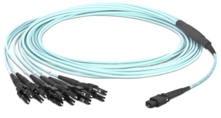
The first FTS implementation solution is called modular panel-mount connectivity. This uses MTP-to-MTP trunk cables to connect to the CPL.

The modular panel-mount boxes are designed so that you can changes the port type in the panel-mount box by unplugging the trunk and changing the modular inserts in the box.

Benefits:

* MTP-to-MTP trunks connect quickly to the panel-mount box.
* The connector type in front of the panel-mount can be easily changed.
* Panel mount capacity can be customized.

The second FTS implementation solution is called coupler plates connetivity. It uses MTP-LC duplex trunk cables to connect to the CPL.

The LC duplex small from factor optical connector is the standard for FTS connectivity, eliminating the need for multiple connector types at patch panels and for patch cables. By standardizing on a connector with a proven history of reliability, the different optical fiber connectors used in equipment do not create a management problem when a system configuration used in equipment do not create a management problem when a system configuration must change. The LC-duplex supports termination of both sizes of multimode fiber and single mode fiber. As a result, CPL patch panel connections and patch cables are easily mangaged and differentiated by their color. There are two key benefits:

* CPC port order at the panel mount is independent of the harness that plugs in at the CPC.
* Single connector type at the CPL

The MTP coupler brackets provide the mechanical support to connect the harness MTP connectors to the trunk cable MTP connector. They are directly mounted on CPC frames.

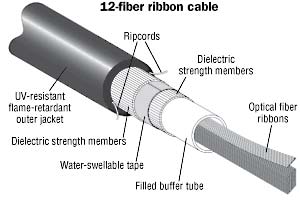
The maximum density of fiber trunk cables is 144 fiber, which use 12 MTP connectors on the CPC trunk cable end. The trunk cables run under the raised floor and connect the harnesses in the CPC to the panel-mount box in the Central Patching Location.

The Anatomy of MPO Trunk Cable Assembly

New cable designs are being developed to address the specific needs of connectorized cable assemblies. There are various industry-standard tests that evaluate the mechanical and environmental performance of cables and another set of standard tests for connectorized assemblies. In many cases, there are choices made in the cable design parameters, which may affect the cable assembly process, without due consideration of the complications that might be added to the assembly processes. Over the past few years, manufacturers have sought to co-develop new cables and the associated cable assemblies, which improve both the performance and processing of the assemblies. Here we report the development of innovative new trunk cables and associated cable assemblies.

Fiber optic cables are designed to meet rigorous standards for cable performance. These requirements include mechanical and environmental testing such as long length tensile testing and temperature cycling. A successful design is judged by how well it meets these requirements. The cable manufacturer then sells the cable to an assembly manufacturer that will furcate and connectorize the fibers from the cable to make a cable assembly.The furcation removes the outer jacket of the cable and prepares the fibers to receive a connector. Additionally, the furcation terminates the cable strength members and must isolate fiber strain in the cable from the connector. The furcation process may include adding a protective furcation leg over the fibers to provide protection between the end of the cable jacket and the connector. The design of the cable has a significant impact on the design and complexity of the furcation. The objective of this effort was to re-design the cable assembly to improve furcation processing and add customer preferred features to the trunk cable assembly.

Traditional high fiber count trunk cable assemblies have been made with fire retardant ribbon cables. These cables have the advantage that the fiber optic ribbons easily mate to the 12-fiber MPO connectors. The MPO connectors are preferred by customers because they allow quick and easy connection of the trunk cables to the MPO/LC breakout modules in a patch panel. However, the rectangular furcation legs have significant preferential bending which may be bothersome during installation. The ribbon trunk cables have several characteristics that may beaggravating during cable assembly and installation. The cables have a ribbon stack contained within a hard plastic buffer tube that is surrounded by tensile yarn and an outer jacket. This design provides a robust cable but makes a fairly stiff cable with a large bend radius,which may be difficult to route during installation. Furthermore, the cable design drives the requirement for a large furcation plug and pulling grip that requires more space for pulling the cable in during installation.

ribbon cable

Cables utilized in preterminated assemblies come in many varieties, but there are some common features to all cables. Cables consist of optical fibers, strength members and an outer protective jacket. The cable designs considered in this work were ribbon cables and non-ribbon cables. Each design used 250 µm colored optical fibers. The ribbon cables had the fibers grouped in a linear array with 12 fibers per ribbon. The unitized cables consist of individual units that contain 12 fibers and aramid yarn. One benefit of using ribbon cable is that the installation of multi-fiber connector is simplified because it is not necessary to group the fibers in such an array to install them into the MPO connector. One detriment of the ribbon cable design is that it necessitates rectangular legs to protect the ribbon in the transition from the furcation to the connector. An advantage of unitized cables is that they enable the use of round furcation legs or, with properly designed cable and furcation, the use of the subunits as the legs themselves. Now the following is the introduction of 12-fiber and 24-fiber trunk cable Assemblies.

trunk cable

MPO Trunk Assemblies are pre-terminated 12-fiber and 24-fiber cable assemblies. The unique design of the MPO Connector allows for rapid gender and polarity change in the field, in support of standards-compliant cable plant migration from 10G cassette-based systems to 40G MPO connector-based parallel optics cable plant. These trunk cable assemblies optimize cable routing requirements to ensure efficient use of pathway space and significantly reduce installation time and cost. All small diameter trunk cable assemblies are factory terminated and tested to deliver verified optical performance and reliability for improved network integrity. 10Gig versions provide 10 Gb/s network performance up to 300 meters for OM3 and up to 550 meters for OM4 per IEEE 802.3ae 10 GbE standard while maintaining compatibility with legacy systems.

10G fiber backbone or permanent link when mated to MTP Cassettes or fiber adapter panels paired with MPO to LC breakout harnesses. Method A and Method B TIA 568-C compliant for 40G parallel optics multimode applications. Allows system designers to tailor configuration, reach and breakout construction to application requirements; to minimize waste, optimize cable management, speed deployment, improve flexibility and manageability for lower installation costs. Small diameter trunk cable assemblies use 30 – 40% less space which is ideal for high cable density applications.