Time-to-Link Test for 1000BASE-T and 10GBASE-T

Background

This post is composed on the basis of the physical layer (PHY) behavior assessment of 1000BASE-T and 10GBASE-T. In order to understand the test results and the meaning of this discussion, some terminologies have to be introduced first.

The Meaning of Time-to-Link

Time-to-link (TTL) is a system performance standard that characterizes and measures the PHY behavior through autonegotiation (AN) and 1G/10GBASE-T startup sequences (correspond to training). It is one of the two primary performance measures (the other is bit error rate) used to characterize BASE-T PHY link rate interoperability.

For Ethernet over twisted pair, autonegotiation is defined in clause 28 of IEEE 802.3. It is a procedure by which two connected devices choose common transmission parameters. In this process, the link partner firstly share their capabilities, such as speed, duplex mode, and flow control, and then choose the highest performance transmission mode they both support.

Since servers networking drivers must meet the third party certifications, the TTL standard used to measure link interoperability becomes rather important. Otherwise, long TTLs (>6s) can lead to device certification failures.

How to Measure the Link Interoperability?

There are several representative link interoperability metrics associated with TTL. Their meanings are explained as follows:

TTL: time to achieve link after link initiate event.

Link attempts number: number of attempts made to resolve Master/Slave status for each link. Within a link, one link partner is designated as the master timing source for transmitted signals in both directions. One partner is Master and one partner is Slave.

Link drops number: number of link drops observed after link is established.

Clock recovery: Some digital data streams, especially high-speed serial data streams, such as Ethernet, are sent without an accompanying clock signal. The receiver generates a clock from an approximate frequency reference, and then phase-aligns the clock to the transitions in the data stream with a phase-locked loop (PLL). This is one method of performing a process commonly known as clock and data recovery (CDR). Here it is also called Master/Slave resolution.

TTL distribution: percentage of links by link time.

Speed downshift/downgrade: resolved speed if other than 10Gbps.

Presentation and Analysis of the Results

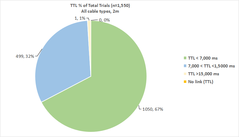
Totally 1550 link tests are performed, and the results are:

  • 1,050 out of 1,550 tests, or 67% of the total number of link tests, achieved a link state in 7s or less (green slice).
  • 499 out of 1,550 tests, or 32% of the total number of link tests, achieved a link state somewhere between 7s and 15s (blue slice).
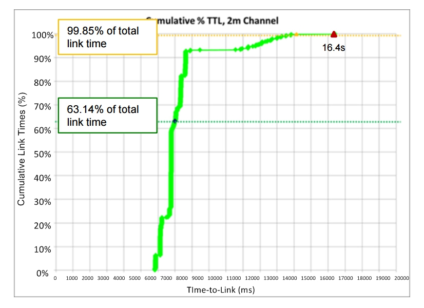
  • 1 out of 1,550 tests, or < 1 % (actually 0.15%) of the total number of link tests, achieved a link state longer than 15s (exactly 16.4s; yellow splice, actually it should be smaller than presented in the pie chart).

TTL % of total trials pie chart

Source: http://www.ieee802.org
Characterizing TTL behavior

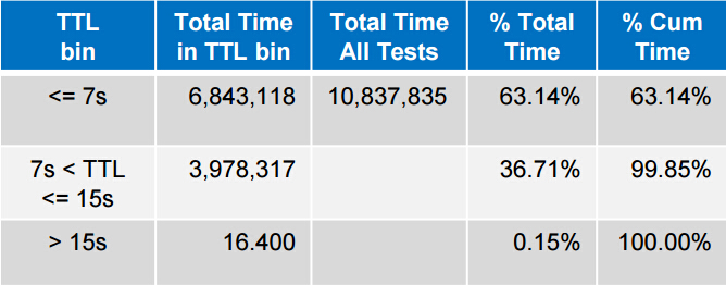
Cumulative percentage (%) TTL is the distribution of measured link times as a percentage of total measured link time. Total link time recorded for all 1,550 tests is 10,837,835ms or about 3h 0min 38sec. The measured link time and cumulative percentage of each result is recorded in following table and chart:

Cumulative percentage TTL

Source: http://www.ieee802.org
TTL behavior

Source: http://www.ieee802.org

TTL Distribution and Master/Salve Resolution by Channel Length

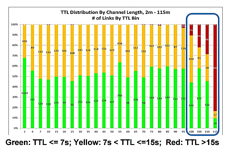
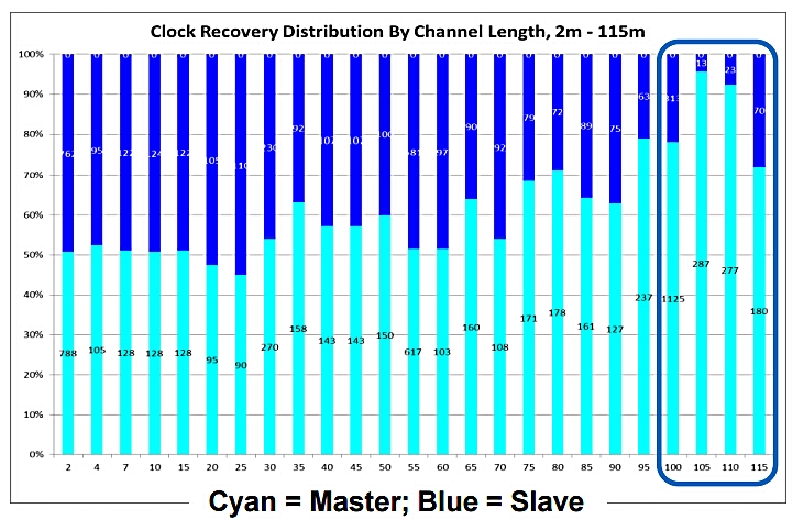
In this part, the example of 10GBASE-T TTL measured from 2m to 115m channels (9790 links) will be given. The average TTL across 2m to 100m is 7.5s; the average time in autonegotiation is 5s; the average time in training is 2.6s. The following two charts illustrate the TTL distribution and clock recovery results by channel lengths from 2m to 115m.

TTL distribution by channel length

Source: http://www.ieee802.org

clock recovery distribution by channel length

Source: http://www.ieee802.org

According to the charts, we can see that there is an apparent loop timing trend towards Master preference with increasing channel length. And very long TTLs (>15s) at >100m channels are associated with downshits to 1Gb link speed.

AN & Training Times for 1000BASE-T and 10GBASE-T

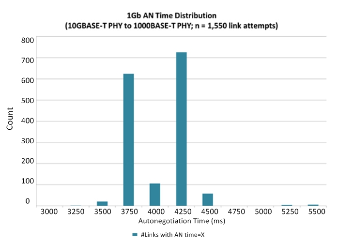
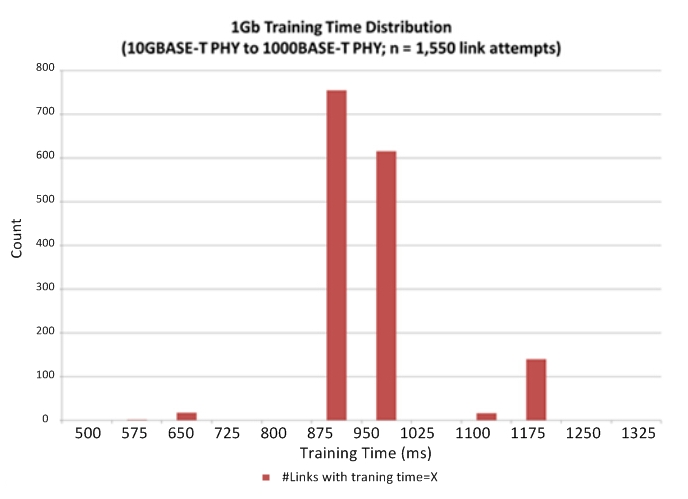
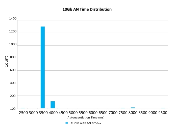
Measured autonegotiation and training times from 1550 1Gb links for 10GBASE-T device to 1000BASE-T link partner, and 10GBASE-T device to 10GBASE-T link partner are respectively:

AN & traning times and TLL

Conclusion

From the test results on 1000BASE-T and 10GBASE-T, user TTL experience of 1000BASE-T installed over Cat5e cable or better is between 3s and 4s, and 10GBASE-T installed over Cat6a or better is about 7s, or longer in some cases. And the measured autonegotiation times for 1000BASE-T and 10GBASE-T are comparable. And for future 2.5/5GBASE-T, it is highly desirable that their autonegotiation and startup times can be improved, and that total TTL be minimized, so as to be more aligned with end-users’ expectations and requirements.

Appendix: AN & Training Times for 1000BASE-T and 10GBASE-T

1G AN time ditribution

1G traning time ditribution

10G AN time ditribution

10G traning time ditribution

Source: http://www.ieee802.org

Why Choose the Shielded Cabling System

Shielded VS. Unshielded

In Network Cabling system at all levels, there are two main technical types: Shielded and Unshielded cabling systems. Since the earliest fabric cabling standards since its establishment types on these two technologies are widespread in the market. Germany, Australia, Switzerland and France in the first preference or relatively shielded cabling system, while in other parts of the world, the more popular non-shielded cabling system and will soon be adopted. Both shielded and unshielded gigabit transfer rate to meet the requirements, but when the transmission rate up to Gigabit or even higher, the shield system to support the stability of the advantages of the high frequency transmission becomes very apparent.

What is the function of shielded?
F/UTP

F/UTP cable shielding structure is four pairs of wires in the data cable outside the contractor a layer of aluminum foil shielded, this layer of shielding can be reduced to a great extent the total package:

1. This is the root of the signal transmission cable radiated interference signals on the impact of adjacent data cable (for example: the same bundle of cables in the adjacent data cable).

2. Interference from other data cable or other interference source signal for this cable.

3. For a high quality data transmission system, which is significant in two kinds of effects. If the external interference signal is strong enough it will happen with the normal transmission signal stack a plus, resulting in reduced transmission performance even the entire system can not work properly.

S/FTP

S/FTP structure in addition to the total package of braided foil shield, Twisted Pair Cable is respectively in each pair with a layer of aluminum foil shield to protect the transmission signal does not interfere with each other, so near-end crosstalk attenuation (NEXT)performance dramatically.  NEXT better performance means higher SNR and better transmission quality and faster system output. S/FTP shielded cables NEXT excellent structural performance of other cables (such as non-shielded U/UTP) can not be compared, therefore, ISO11801 on the Cat 7 (600MHz) and Cat 7a  (1000MHz) only provides the S/FTP cable structure, U/UTP cannot meet.

10GBase-T make data cable is facing new problems: Alien Crosstalk

2006 Copper Gigabit Ethernet applications published the proposed new standard transport protocols 10GBASE-T compared to 1000Base-T, its transmission rate increased 10 times. 1000BASE-T copper cabling required parameters (Attenuation, NEXT, Return Loss, etc.) the bandwidth required to reach 1-100MHz, with UTP Cat 5e (Class D) cabling system to meet requirements. 10GBASE-T cabling channel requirements of all component parameters have to be up to 500MHz bandwidth, which requires copper to reach at least Cat.6A (Class Ea) or higher level.

Along with the development of 10GBASE-T, external noise problems become more evident, resulting in a specification for external noise to be used to assess in the same bundle of cables, the interaction between different cables. This is what we call Alien Crosstalk. Alien Crosstalk will increase with the increase of frequency. Worse, 10GBASE-T confronted with external noise, will not be able to “adaptive” to lower the rate at which the network may be subsequently face paralysis. Therefore, to support 10GBASE-T cabling system application, the ability to resist alien crosstalk is vital.

  • Since 10GBASE-T high transmission frequencies and complex coding method is very sensitive to the external noise.
  • Shielding system excellent coupling atttenuation performance makes it naturally have to resist alien crosstalk.
  • The unshielded system against alien crosstalk is usually only on the performance of 0dB.
  • Shielding system in the design is completely satisfy the application of 10G.
The installation of 10GBase-T: U/UTP VS. FTP

Unshielded system: As far as possible away from power cable during installation; Different applications (1Gb/s and 10Gb/s) in the same pipeline transmission will cause the external crosstalk.

Shielding system: With the power cable can be reduced separation distance; Allow different applications (1 Gb / s and 10 Gb / s) in the same pipeline transmission; Does not need additional external crosstalk test field.

The separation distance between the data cable and power cable

In EN50174 standard defines the content of different coupling attenuation value level of data cable, respectively, from A (low coupling attenuation, worse) to D (high coupling attenuation, good) four levels.

Installers need to know which cable separated levels to determine the choice of the data requirements of the standard cable with power cable between the minimum separation distance. Data cable coupling attenuation higher the value and power cables minimum separation distance between the smaller.

Relative to the shielded cable, the unshielded (U/UTP) separation distance between cable and power cable to further. In the implementation of the project, if need the data cable and power cable isolation far distance, we need a bigger size pipe/bridge, or even additional bridge, doing this will no doubt have higher cost, sometimes limited to the bridge installation space. To make matters worse, these additional requirements often neglected or ignored, resulting in network system is the key point of interference.

Grounding

For shielded, unshielded systems and Fiber Optics Cable, all need to implement protective grounding. Because of the need to consider personal and equipment safety, therefore no matter adopt what kind of cabling system, the metal part of the system must be grounded.

For the shielding system, also need to implement the functional ground. Grounded shielding system functions with respect to the implementation of non-shielded systems only difference is that when you install the module connector and the cable shielding mask area area connected.

Overview

Shielding system relative to the unshielded system has been greatly improved EMC performance. For Gigabit Ethernet applications, shielding against external interference effects is essential, and shielded cabling system had to meet the standards in the design of anti-alien crosstalk (A-XT) requirements, can effectively prevent the cable from the adjacent between the external crosstalk.

110 Punch Down Block Wiring System

Punch down block, also referred to as a cross-connect block, terminating block, or a connecting block, is a device that connects one group of wires to another group of wires through a system of metal pegs that the wires are attached to, often used in telecommunications closets that support LAN(Local Area Network). Punch down blocks are the predecessors to patch panels and were commonly used to support low-bandwidth Ethernet and token-ring networks.

There are two styles of punch down blocks available for telephony, the 66 block and the 110 block, these blocks are used to connect station cabling to the trunk cabling that goes from an IDF to the MDF.

110 Punch Down Block

A 110 blocks is a updated version of punch down block, is the core part of the connection management system, used to connect wiring for telephone systems, data network wiring, and other low-voltage wiring applications. 110 type wiring block is flame retardant, injection-molded plastic to do the basic devices and the termination cabling system is connecting on it.

The 110 block is designed for 22 through 26 gauge solid wire. This is the termination used on Cat5e Patch Panels, cat 6 patch panel and RJ-45 jacks. They are also formed into block type terminations the size of small 66 blocks. The 110 block is designed for 500 MHz (1 gb/s) or greater bandwidth. 110 blocks are acceptable for use with AES/EBU digital audio at sample rates greater than 268 KHz as well as gigabit networks and analog audio.

The specifications of 110 Blocks are as follows: 25 pairs 110 type wiring block, 50 pairs 110 type wiring block, 110 pairs 110 type wiring block, 300 pairs 110 type wiring block. The distribution frame package of 110 type wiring blocks should also include 4 or 5 blocks, connection block, blank labels and tags folder and the base. 110 type wiring block system uses easy quick-fit plug-hop loops which can be simply rearranged, so it provides a convenient cross-connect to non-professional and technical personnel management system.

110 Punch Down Tool

A Punchdown Tool is used to force solid wire into metal slots on the 110 block. Present residences typically have phone lines entering the house to a sole 110 block, and then it is spread by on-premises wiring to outlet boxes all over the house in a star topology.

Both styles of punch block use a punch down tool to terminate the wires to the block. To terminate a wire, you place it into the terminal and then push it down to make contact with the punch down tool. The punch down tool fits around a 66 block terminal or into a 110 block terminal. One side of the blade is sharp to cut the wire off flush, this is normally marked on the tool with the word cut. Be sure to have this side oriented to cut off the loose end of the wire and not the end going to the other block. Hide extra cable behind the block in case you ever have to reterminate a pair so that you don’t have to reterminate the entire cable.

Whatever the dimensions of the punch down tools are, usage is the same. Many tools have a dual blade that can be flipped depending on which style of block is in use.