
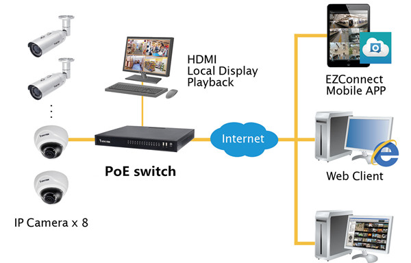
PoE is a networking technology that supplies power to network devices over existing data connections. Various applications in our lives, such as new wireless access points, cameras and some types of security devices, are using this technology. Because it can bring many benefits: one cable for both power and data transmission; simpler deployment of devices; and no need to upgrade existing cabling systems. This post explores some basic knowledge about the main elements of PoE technology.
The IEEE 802.3af is a standard that defines how power would be delivered to devices utilising 10BASE-T, 100BASE-T and 1000BASE-T technologies. It defines the delivery of up to 15.4 watts per port to Ethernet devices, typically using 48 volts. Generally, many devices like IP phones, hand-held PCs, and magnetic card readers are being developed to utilise IEEE 802.3af. Besides, this standard also defines two major pieces of hardware, the power device (PD, receiving power) and power sourcing equipment (PSE, delivering power to PD).
Except for the function to deliver power to PD, the PSE has other two functions: detect a PoE-capable PD and monitor and terminate the supplied power. There are two types described in the definition of a PSE: endpoint PSE and midspan PSE. An endpoint PSE is a PoE-capable port on a switch that is directly connected to the cable supplying power to the PD. Power is delivered by the endpoint PSE using either the active data pairs (usually the orange and green pairs in Ethernet—Pins 1,2 and 3,6) or the spare pairs (usually the brown and blue pairs—4,5 and 7,8). These two delivery methods are referred to as alternatives A and B. Alternative A uses the active data pairs, and alternative B uses the spare pairs. Just like the following picture shows.
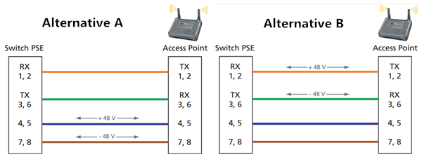
To be 802.3af compliant, the PSE must support both alternatives A and B. However, only one method will be used to provide power to a device. Typically, this will be the A method for the standard 802.3af PSE.
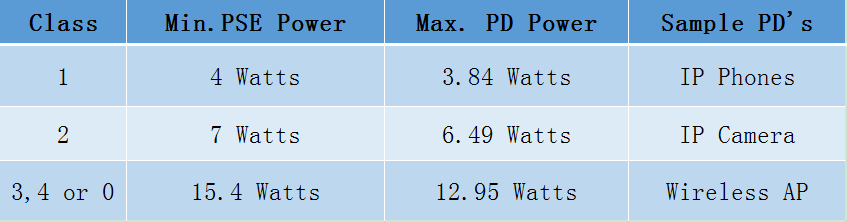
As mentioned above, a PD is a device to receive power. An 802.3af-compliant powered device can accept power using either the alternative A or B method. It doesn’t support receiving power on devices that require power on either the data pair or spare pair that are not compliant, or the devices that need power on four pairs. What’s more, PDs can be qualified into classes according to their power needs. In a start-up process, when a PoE connection is made, the PD can advertise its power class to show how much power is required. The following picture is an example.
PoE+ was created in 2004. It’s an update to PoE. It is compliant with IEEE802.3at, aiming to provide more power for devices. That’s the major difference between PoE and PoE+. Besides, the PSEs of PoE+ can supply power to both PoE and PoE+ PDs. But the converse version cannot go through, for PoE+ PDs require more power than PoE PSEs can provide. PoE+ technology is also prevalent in business applications. For example, some managed gigabit switches based on PoE+ technology deliver robust performance and intelligent switching for growing business networks.
With the rapid growth of telecommunications, the use of PoE to power devices such as wireless access points, VoIP phones, and computers is also getting frequent. Therefore, demand for PoE goes up, and so does the demand for the amount of power provided, which puts forward more requirements for PoE. Another problem is the overall power draw to the switch itself.
Summary
PoE is increasingly being applied to provide power to devices like phones, surveillance and laptops used in our daily lives. And PoE switches and PoE media converters for Ethernet networks bring convenience to small business networking systems. Getting an understanding of the basic components of PoE is beneficial to make it work better for our lives.