As large-scale data centers transition to faster and more scalable infrastructures and with the rapid adoption of hyperscale cloud infrastructures and services, existing 100G networks fall short in meeting current demands. As the next-generation mainstream port technology, 400G significantly increases network bandwidth, enhances link utilization, and assists operators, OTT providers, and other clients in effectively managing unprecedented data traffic growth.
To meet the demand for higher data rates, FS has been actively developing a series of 400G products, including 400G switches, optical modules, cables, and network adapters.
FS 400G Switches
The emergence of 400G data center switches has facilitated the transition from 100G to 400G in data centers, providing flexibility for building large-scale leaf and spine designs while reducing the total number of network devices. This reduction can save costs and decrease power consumption. Whether it’s the powerful N9510-64D or the versatile N9550 series, FS 400G data center switches can deliver the performance and flexibility required for today’s data-intensive applications.
Of particular note is that, as open network switches, the N8550 and N9550 series switches can enhance flexibility by freely choosing preferred operating systems. They are designed to meet customer requirements by providing comprehensive support for L3 features, SONiC and Broadcom chips, and data center functionalities. Additionally, FS offers PicOS-based open network switch operating system solutions, which provide a more flexible, programmable, and scalable network operating system (NOS) at a lower total cost of ownership (TCO).
FS 400G Transceivers
FS offers two different types of packaging for its 400G transceivers: QSFP-DD and OSFP, developed to support 400G with performance as their hallmark. Additionally, FS provides CFP2 DCO transceivers for coherent transmission at various rates (100G/200G/400G) in DWDM applications. Moreover, FS has developed InfiniBand cables and transceivers to enhance the performance of HPC networks, meeting the requirements for high bandwidth, low latency, and highly reliable connections.
FS conducts rigorous testing on its 400G optical modules using advanced analytical equipment, including TX/RX testing, temperature measurement, rate testing, and spectrometer evaluation tests, to ensure the performance and compatibility of the optical modules.
FS 400G Cables
When planning 400G Ethernet cabling or connection schemes, it’s essential to choose devices with low insertion loss and good return loss to meet the performance requirements of high-density data center links. FS offers various wiring options, including DAC/AOC cables and breakout cables. FS DAC/AOC breakout cables provide three connection types to meet high-density requirements for standard and combination connector configurations: 4x100G, 2x200G, and 8x50G. Their low insertion loss and ultra-low crosstalk effectively enhance transmission performance, while their high bend flexibility offers cost-effective solutions for short links.
FS 400G Network Adapters
FS 400G network adapters utilize the industry-leading ConnectX-7 series cards. The ConnectX-7 VPI card offers a 400Gb/s port for InfiniBand, ultra-low latency, and delivers between 330 to 3.7 billion messages per second, enabling top performance and flexibility to meet the growing demands of data center applications. In addition to all existing innovative features from previous versions, the ConnectX-7 card also provides numerous enhanced functionalities to further boost performance and scalability.
FS 400G Networking Soluitons
To maximize the utilization of the 400G product series, FS offers comprehensive 400G network solutions, such as solutions tailored for upgrading from 100G to high-density 400G data centers. These solutions provide diverse and adaptable networking options customized for cloud data centers. They are designed to tackle the continuous increase in data center traffic and the growing need for high-bandwidth solutions in extensive 400G data center networks.
Choosing the right MTP/MPO cable ensures efficient and reliable data transmission in today’s fast-paced digital world. With the increasing demand for high-speed connectivity, it is essential to understand the importance of core numbers in MTP/MPO cables. In this guide, we will explore the significance of core numbers and provide valuable insights to help you decide when selecting the right MTP/MPO cable for your specific needs. Whether setting up a data center or upgrading your existing network infrastructure, this article will serve as a comprehensive resource to assist you in choosing the right MTP/MPO cable.
What is an MTP/MPO cable
An MTP/MPO cable is a high-density fiber optic cable that is commonly used in data centers and telecommunications networks. It is designed to provide a quick and efficient way to connect multiple fibers in a single connector.
MPO and MTP cables have many attributes in common, which is why both are so popular. The key defining characteristic is that these cables have pre-terminated fibers with standardized connectors. While other fiber optic cables have to be painstakingly arrayed and installed at each node in a data center, these cables are practically plug-and-play. To have that convenience while still providing the highest levels of performance makes them a top choice for many data center applications.
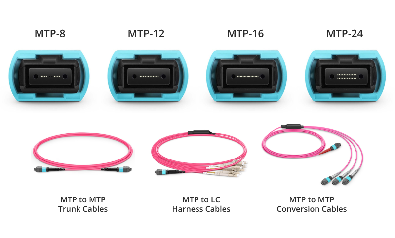
MTP/MPO trunk cables, typically used for creating backbone and horizontal interconnections, have an MTP/MPO connector on both ends and are available from 8 fibers up to 48 in one cable.
MTP/MPO Harness/Breakout Cables
Harness/Breakout cables are used to break out the MTP/MPO connector into individual connectors, allowing for easy connection to equipment. MTP/MPO conversion cables are used to convert between different connector types, such as MTP to LC or MTP to SC.
The MTP/MPO cables also come in different configurations, such as 8-core, 12-core, 16-core, 32-core, and more, depending on the specific needs of the application. This flexibility in configurations enables users to tailor their choices according to the scale and performance requirements of their networks or data centers. As technology advances, the configurations of MTP/MPO cables continually evolve to meet the increasing demands of data transmission.
How to Choose MTP/MPO cables
Selecting the appropriate core number for MTP/MPO cables resonates throughout the efficiency and performance of networks. In this section, we’ll delve into the decision-making factors surrounding core numbers in cables.
Network Requirements and Data Transmission Goals
Different network applications and data transmission needs may require varying numbers of cores. High-density data centers might necessitate more cores to support large-capacity data transmission, while smaller networks may require fewer cores.
Compatibility with Existing Infrastructure
When choosing the core number for MTP/MPO cables, compatibility with existing infrastructure is crucial. Ensuring that the new cables match existing fiber optic equipment and connectors helps avoid unnecessary compatibility issues.
Consideration for Future Scalability
As businesses grow and technology advances, future network demands may increase. Choosing MTP/MPO cables with a larger number of cores allows for future expansion and upgrades.
Budget and Resource Constraints
Budget and resources also play a role in core number selection. Cables with a larger number of cores tend to be more expensive, while cables with fewer cores may be more cost-effective. Therefore, finding a balance between actual requirements and the available budget is essential.
MTP/MPO Cabling Guide to Core Numbers
40G MTP/MPO Cabling
A 12-fiber MTP/MPO connector interface can accommodate 40G, which is usually used in a 40G data center. The typical implementations of MTP/MPO plug-and-play systems split a 12-fiber trunk into six channels that run up to 10 Gigabit Ethernet (depending on the length of the cable). 40G system uses a 12-fiber trunk to create a Tx/Rx link, dedicating 4 fibers for 10G each of upstream transmit, and 4 fibers for 10G each of downstream receive.
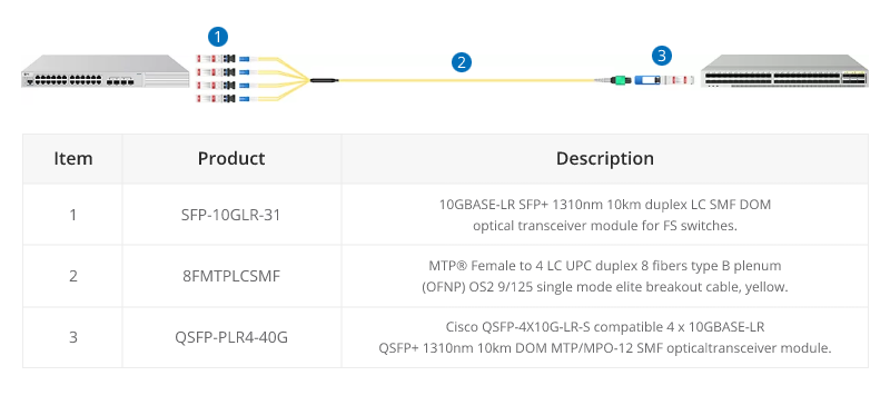
40G-10G Connection
In this scenario, a 40G QSFP+ port on the FS S5850 48S6Q switch is split up into 4 10G channels. An 8-fiber MTP-LC harness cable connects the 40G side with its MTP connector and the four LC connectors link with the 10G side.
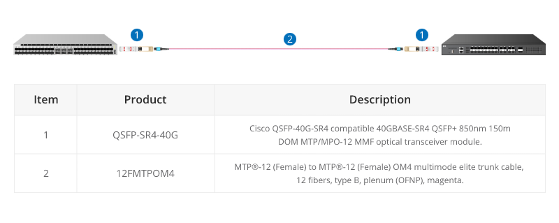
40G-40G Connection
As shown below, a 12-fiber MTP trunk cable is used to connect two 40G optical transceivers to realize the 40G to 40G connection between the two switches. The connection method can also be applied to a 100G-100G connection.
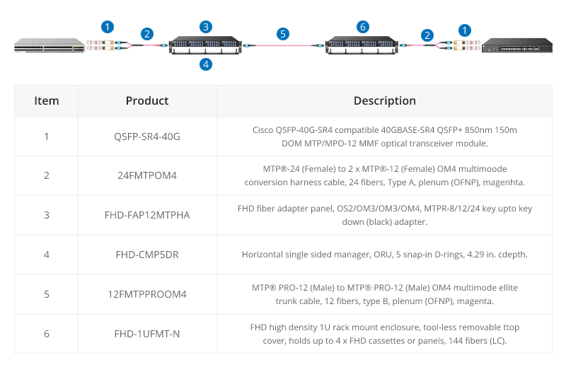
40G Trunk Cabling
24 Fibers MTP® to MTP® Interconnect Conversion Harness Cable is designed to provide a more flexible multi-fiber cabling system based on MTP® products. Unlike MTP® harness cable, MTP® conversion cables are terminated with MTP® connectors on both ends and can provide more possibilities for the existing 24-fiber cabling system. The 40/100G MTP® conversion cables eliminate the wasted fibers in the current 40G transmission and upcoming 100G transmission. Compared to purchasing and installing separate conversion cassettes, using MTP® conversion cables is a more cost-effective and lower-loss option.
100G MTP/MPO Cabling
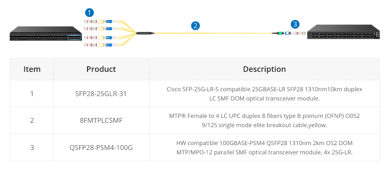
QSFP28 100G transceivers using 4 fiber pairs have an MTP/MPO 12f port (with 4 unused fibers). Transmission for short distances (up to 100m) could be done most cost-effectively over multimode fiber using SR4 transmission. Longer distances over single mode use PSM4 transmission over 8 fibers. Transmission over 4 fiber pairs enables both multimode and single-mode transceivers to be connected 1:4 using MPO-LC 8 fiber breakout cables. One QSFP28 100G can connect to four SFP28 25G transceivers.
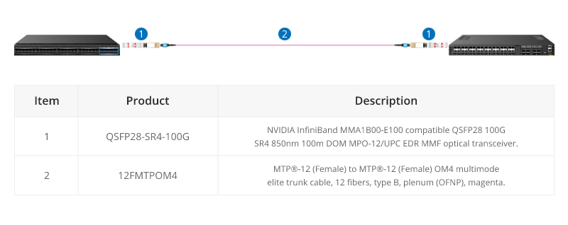
100G SR4 Parallel BASE-8 over Multimode Fibre
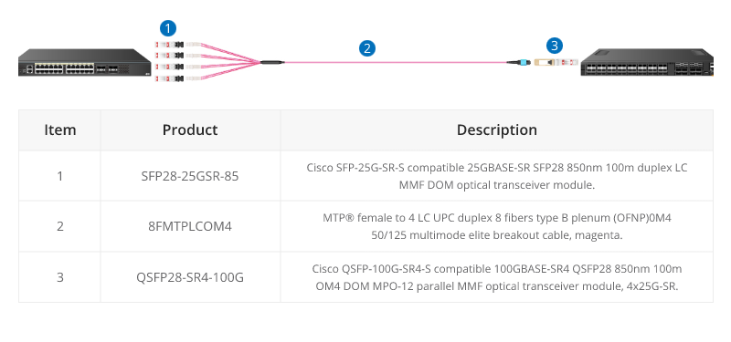
QSFP28 100G SR4 are often connected directly together due to their proximity within switching areas.
Equally QSFP28 SR4 are often connected directly to SFP28 25G ports within the same rack. For example, from a switch 100G port to four different servers with 25G ports.
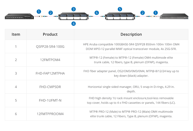
The 12-core MTP/MPO cables can also be used for 100G parallel to parallel connection. Through the use of MTP patch panels, network reliability is enhanced, ensuring the normal operation of other channels even if a particular channel experiences a failure. Additionally, by increasing the number of parallel channels, it can meet the continuously growing data demands. This flexibility is crucial for adapting to future network expansions.
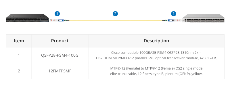
100G PMS4 Parallel BASE-8 over Singmode Fibre
QSFP28 100G PMS4 are often connected directly together due to their proximity within switching areas.
Equally QSFP28 ports are often connected directly to SFP28 25G ports within the same rack. For example, from a switch 100G port to four different servers with 25G ports.
200G MTP/MPO Cabling
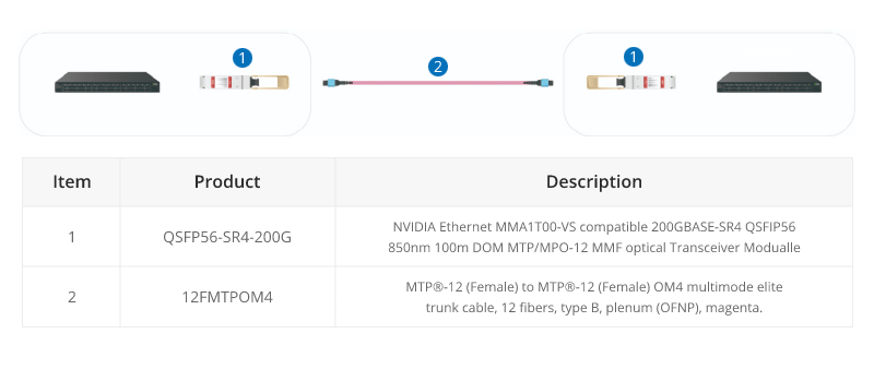
Although most equipment manufacturers (Cisco, Juniper, Arista, etc) are bypassing 200G and jumping from 100G to 400G, there are still some 200G QSFP-DD transceivers on the market, like FS QSFP56-SR4-200G and QSFP-FR4-200G.
200G-to-200G links
MTP (MPO) 12 fiber enables the connection of 2xQSFP56-SR4-200G to each other.
400G MTP/MPO Cabling
MTP/MPO cables with multi-core connectors are used for optical transceiver connection. There are 4 different types of application scenarios for 400G MTP/MPO cables. Common MTP/MPO patch cables include 8-fiber, 12-core, and 16-core. 8-core or 12-core MTP/MPO single-mode fiber patch cable is usually used to complete the direct connection of two 400G-DR4 optical transceivers. 16-core MTP/MPO fiber patch cable can be used to connect 400G-SR8 optical transceivers to 200G QSFP56 SR4 optical transceivers, and can also be used to connect 400G-8x50G to 400G-4x100G transceivers. The 8-core MTP to 4-core LC duplex fiber patch cable is used to connect the 400G-DR4 optical transceiver with a 100G-DR optical transceiver.
In the higher-speed 800G networking landscape, the high density, high bandwidth, and flexibility of MTP/MPO cables have played a crucial role. Leveraging various branching or direct connection schemes, MTP/MPO cables are seamlessly connected to 800G optical modules, 400G optical modules, and 100G optical modules, enhancing the richness and flexibility of network construction.
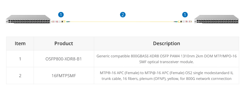
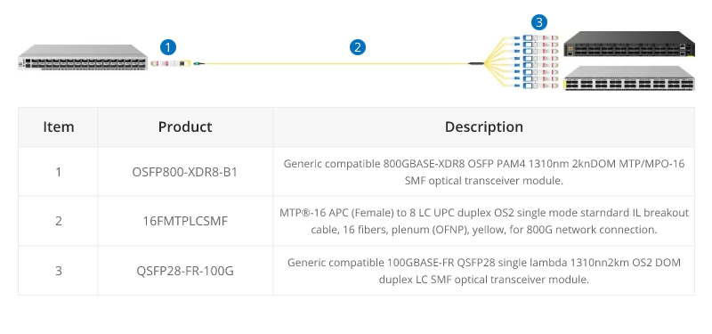
800G Connectivity with Direct Connect Cabling
16 Fibers MTP® trunk cable is designed for 800G QSFP-DD/OSFP DR8 and 800G OSFP XDR8 optics direct connection and supporting 800G transmission for Hyperscale Data Center.
16 fibers MTP®-LC breakout cables are optimized for 800G OSFP XDR8 to 100G QSFP28 FR, 800G QSFP-DD/OSFP DR8 to 100G QSFP28 DR optics direct connection, and high-density data center applications.
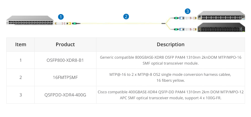
800G to 2X400G Interconnect
16 fiber MTP® conversion cable is designed to provide a more flexible multi-fiber cabling system based on MTP® products. Compared to purchasing and installing separate conversion cassettes, using MTP® conversion cables is a more cost-effective and lower-loss option. In the network upgrade from 400G to 800G, the ability to directly connect an 800G optical module and two 400G optical modules provides a more efficient use of cabling space, resulting in cost savings for cabling.
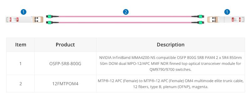
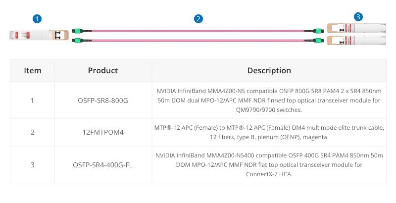
When using InfiniBand technology for networking purposes, 12 fibre MTP® trunk cable is designed for linking InfiniBand and Ethernet multimode twin-port OSFP and single-port OSFP and QSFP112 transceivers together.
Conclusion
In a word, the choice of core number for MTP/MPO cables depends on the specific requirements of the network application. Matching the core number with the requirements of each scenario ensures optimal performance and efficient resource utilization. A well-informed choice ensures that your MTP/MPO cable not only meets but exceeds the demands of your evolving connectivity requirements.
How FS Can Help
As a global leader in enterprise-level ICT solutions, FS not only offers a variety of MTP/MPO cables but also customizes exclusive MTP/MPO cabling solutions based on your requirements, helping your data center network achieve a smooth upgrade. In the era of rapid growth in network data, the time has come to make a choice – FS escorts your data center upgrade. Register as an FS website member and enjoy free technical support.
Optical fiber cables have become one of the key points in the 5G competition. It’s known that 5G networks will offer consumers high-speed and low-latency services with more reliable and stronger connections. But to make this happen, more 5G base stations have to be built due to the higher 5G frequency band and limited network coverage. And it’s estimated that by 2025, the total number of global 5G base stations will reach 6.5 million, which puts forward higher requirements for the optical fiber cable performance and production.
Currently, there are still some uncertainties in 5G network architectures and the selection of technical solutions. But in the basic physical layer, the 5G fiber cables should meet both current application and future development needs. The following are five types of optical fiber cables that address problems in 5G networks built to some degree.
1. Bend Insensitive Optical Fiber for Easy 5G Indoor Micro Base Stations
The dense fiber connections between massive 5G new macro base stations and indoor micro base stations are the main challenge in the 5G access network constructions. The complex cabling environments, especially the indoor fiber cabling, and the limited space and bend request high requirements for the fiber bend performance. Optical fiber compliant ITU G.657.A2/B2/B3 has great bend-improved performance, which can be stapled and bent around corners without sacrificing performance.
Many fiber manufacturers have announced bend-insensitive fiber (BIF) cables with low loss to address such problems in 5G indoor applications.
Company
Product Name
ITU Standards
Bend Radius (1 turn around a mandrel)
Induced Attenuation (dB)
Corning
ClearCurve LBL fiber
G.652.D, G.657.A2/B2
7.5 mm
≤ 0.4
YOFC
EasyBand® Ultra BIF
G.652.D, G.657.B3
5 mm
≤ 0.15
Prysmian Group
BendBright XS fiber
G.652.D, G.657.A2/B2
7.5 mm
≤ 0.5
Note: The induced attenuation is caused due to fiber wrapped around a mandrel of a specific radius.
2. OM5 Multimode Fiber Applied to 5G Core Networks
5G service providers also have to focus on the fiber optic network build of the data centers where the content is stored. At present, the transmission speed of data centers is evolving from 10G/25G, 40G/I00G to 25G/I00G, 200G/400G, which put forward new requirements for the multimode optical fibers used for interconnection inside the data centers. Multimode optical fibers need to compatible with the existing Ethernet standard, cover the future upgrades to higher speed like 400G and 800G, support multi-wavelength multiplexing technologies like SWDM and BiDi, and also need to provide excellent bending resistance to adjust to dense data centers cabling scenarios.
Figure 1: OM5 fiber in 100G BiDi and 100G SWDM applications
Under such conditions, the new broadband OM5 multimode fiber becomes the hotspot option for data center constructions. OM5 fiber allows multiple wavelengths to be transmitted simultaneously in the vicinity of 850 nm to 950 nm. By adopting the PAM4 modulation and WDM technology, OM5 optical fiber is able to support 150 meters in 100Gb/s, 200Gb/s, and 400Gb/s transmission systems, and ensure the ability of future short-distance and high-speed transmission networks, making it the optimal choice for intra-data center connections under the 5G environment.
Here is a comparison of the link length of OM5 and other multimode fiber over 850nm wavelength.
Link Length (M) @850nm wavelength
Fiber Type
10GBASE-SR
25GBASE-SR
40GBASE-SR4
100GBASE-SR4
400GBASE-SR16
400GBASE-SR8
400GBASE-SR4.2
OM3
300
70
100
70
100
70
70
OM4
550
100
150
100
150
100
100
OM5
550
100
150
100
150
100
150
3. Micron Diameter Optical Fibers Enable Higher Fiber Density
Due to the complex deployment environments of the access layer or aggregation layer of 5G bearer networks, it’s easy to encounter problems like the limited existing cable pipeline resources. To ensure the limited space can hold more optical fibers, cable manufacturers are working hard to reduce the size and diameter of cable bundles. For example, recently the Prysmian Group has introduced the BendBright XS 180µm single-mode fiber to meet the 5G technology demands. This innovative optical fiber enables cable designers to offer strongly reduced cable dimensions while still keeping the 125µm glass diameter.
Figure 2: Prysmian’s BendBright XS 180µm fiber
Similarly, with the same principles, Corning has introduced the SMF-28 Ultra 200 fiber that allows fiber cable manufacturers to shave 45 microns off previous cable coating thicknesses, going from 245 microns down to 200 microns, to achieve a smaller overall outer diameter. And YOFC, another optical fiber manufacturer, also provides EasyBand plus-Mini 200μm reduced diameter bending insensitive fiber for 5G networks, which can reduce the cable diameter by 50% and significantly increase the fiber density in pipelines when compared with common optical fibers.
4. ULL Fiber with Large Effective Area Can Extend 5G Link Length
5G fiber manufacturers are actively exploring ultra low-loss (ULL) optical fiber technologies to extend the fiber reach as long as possible. The G.654.E optical fiber is such a type of innovative 5G fiber. Different from the common G.652.D fiber often used in 10G, 25G, and 100G, the G.652.E fiber comes with a larger effective area and ultra-low loss features, which can significantly reduce the nonlinear effect of optical fiber and improve the OSNR that are easily affected by higher signal modulation format in 200G and 400G connections.
Speed (bps)
40G
100G
400G
400G
Fiber Type
common G.652
low-loss G.652
low-loss G.652
innovative G.654.E
Maximum Capacity (Tbs)
3.2
8
20
20
Limit Relay Distance (km)
6000
3200
<800
<2000
Typical Link Attenuation (dB/km)
0.21
0.20
0.20
0.18
Fiber Effective Area (µm²)
80
80
80
130
With the continuous increase of the transmission speed and capacity of the 5G core network and the clouded data center, fiber optic cables like this will be needed more. It’s said that the latest Corning’s TXF fiber, a type of G.654.E fiber, comes with high-data-rate capabilities and exceptional reach, able to help network operators deal with growing bandwidth demands while lowering their overall network costs. Recently, Infinera and Corning have achieved 800G across 800km using this TXF fiber, which shows this fiber is expected to offer excellent long-haul transmission solutions for 5G network deployment.
5. Optical Fiber Cable for Faster 5G Network Installation
5G network deployment covers both indoor and outdoor scenarios, the installation speed is a factor needed to consider. Full-dry optical cable using dry water-blocking technology is able to improve fiber splicing speed during cable installation. Air-blown micro cables are compact and lightweight and contain high fiber density to maximize the fiber count. This type of cable is easy to be installed in longer ducts with multiple bends and undulations, and it can save in manpower & installation time and improved installation efficiency via the blowing installation methods. For the outdoor fiber cable deployment, some anti-rodent and anti-bird optical cables also need to be used.
Get Ready for 5G Networks
Currently, optical fiber is the optimal medium capable of scaling to the 5G demands. 5G networks’ enhanced bandwidth capacity, lower latency requirements and complicated outdoor deployments bring challenges as well as unlimited possibilities for optical fiber manufacturers, but our optical networks must quickly adapt to meet such new demands. Except for the optical fiber mentioned above, it remains to be seen if the 5G fiber manufacturers will put forward other innovative fiber for the market as quickly as possible.
Why should fiber optic cable not be tightly bent? Are fiber optic cable fragile? These issues are what users care about when deploying fiber patch cables. Usually, fiber optic cable is made from two bend sensitive materials: plastic or glass. It is broken easily when kinked or bent too tightly to exceed the minimum bend radius of cable. Then which factor will influence bend radius? How to choose cables according to it? This blog will provide some hints.
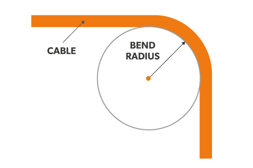
Why Bend Radius Is Important?
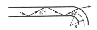
When you deploy the fiber optic cable, it is inevitable to flex, pull and bend it due to the practical conditions. However, it is the bend radius that determines how much you can bend a cable. It represents as the safe value that can prevent your cable from damaging or degrading its performance. If a cable is bent beyond its allowed radius, it will generate crosstalk or interference in data transmission, or even shorten its life. That’s why it’s important to know the bend radius of the cables, especially the minimum bend radius,which is the smallest allowed radius the cable can be bent around without signal loss or impairment.
Factors Impact Bend Radius of Cable
The bend radius may differ from cables. The fact is the smaller the minimum bend radius, the more flexible the cable. Here list some factors that may affect this radius of cable.
Outer Jacket Thickness
The thickness of the outer jacket of a fiber patch cable intended for bending will influence the potential minimum curve radius. Generally speaking, if the outer jacket is thick, the fiber patch cable will have a smaller bend radius. This can be translated by the fact that when the cable is bent, the stretching force makes the outer jacket thinner and even broken. Therefore, if the outer jacket is thin itself, the external tension may deform of break the fragile cable.
Material Ductility
Cables are manufactured by different materials, and this will affect the radius of the bend. Ductility refers to the flexibility of material under tensile stress or stretching force. If you would like to obtain small curve radius, you should choose cables made of highly ductile materials like copper. An alternative such as glass is more brittle than flexible.
Core Diameter
The large core diameter determines the small bend radius. Simply put, the single mode fiber has a smaller diameter than multimode fiber, and the single mode fiber cable bears less weight or bending than multimode fiber cable. That’s why the bending radius of single mode fiber optic cable is larger than the multimode fiber optic cable.
How to Choose Fiber Optic Cables based on Bend Radius?
Generally, the multimode fiber optic cable is recommended if the bend radius is the only consideration. And another option is BIF fiber cable. BIF means the bend insensitive fiber which enables tight curve radius when cables are bent or twisted. FS adopts it in producing both multimode and single mode fiber cables to endow them much smaller bend radii than ever before. It realizes more convenience in cable management, as well as less signal loss and less cable damaging. Here is a bend radius chart of BIF fiber optic cable.
Fiber Cable Type
Minimum Bend Radius
OM3/OM4 MTP BIF
7.5mm
Single Mode OS2 MTP BIF
10mm
Uniboot OS2 LC BIF
10mm
Uniboot OM3/OM4 LC BIF
7.5mm
Conclusion
To sum up, the bend radius of cables is paramount for fiber patch cable installations. Factors which influence the minimum radius of fiber optic cable include the outer jacket thickness, material ductility and core diameter. To protect the integrity and performance of cable, we shall not bend the cable beyond its allowed radius.
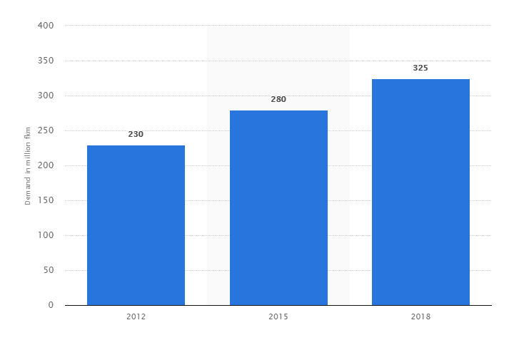
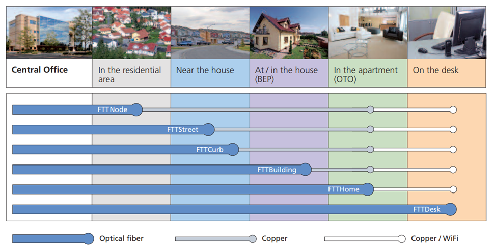
An optical fiber cable uses light wave for voice and data transmission, its data transmission capacity is 4.5 times more than conventional copper cables. So in the past several decades, we have seen that fiber optic cables are superior to traditional copper twisted-pair cable or coaxial cable because of its unique physical characteristics, allowing information to travel at speeds increasingly approaching the speed of light without interference between adjacent wavelengths. In leading market, the global drive to implement FTTx into more new venues is good news for the market of optical fiber cables. Another good trend is that the price erosion of optical fiber cables had been 10 to 15 percent annually, in result that the demand of optical fiber cable is expected to continue growing in the foreseeable future. And the growing data transmission workloads placed by high-performance computers, servers and network storage systems is helping spur growth in the market. Consequently, fiber optic cables are now the indispensable backbone of today’s communication network. This article will analyse the global optical fiber cable market in three main applications, including long-distance communication, submarine cable and FTTx network.
Global Optical Fiber Cable Market to Grow at 9.8% till 2021
According to the report “Fiber Optics Market by Cable – Global Forecast to 2021”, the optical fiber cable market is anticipate to grow at a CAGR of over 9.8% during 2016-2021. The growing importance of cloud computing, data transfer & storage, and IoT is driving the use of Internet, which is driving the fiber optic cable market, as it acts as the backbone for data transmission. Moreover, growing technological advancements increase in number of connected devices and data centers are expected to positively influence global optical fiber cable market. In addition, next generation technologies such as LTE and FTTx, which require last mile connectivity, is expected to propel the demand for optical fiber cables in the coming years. All these factors have led to an increase in Internet users, which in turn has led to the higher usage of optical fiber cable to transfer information over the Internet, thus driving the fiber optics market.
Global Optical Fiber Cable Demand from 2012 to 2018 (Source: Statista)
Optical Fiber Cable Market in Long-distance Communication
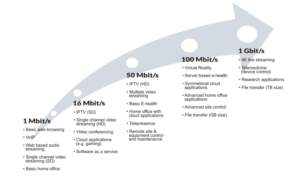
Currently, the growing adoption of optical technology in the telecommunications appears to be promising. Optical fiber has virtually unlimited capacity and low signal attenuation allowing long distances without amplifier or repeater, no exposure to parasite signals or crosstalk, and no electromagnetic interference (EMI). So fiber optic cable is especially advantageous for high-speed data transfer services in long-distance communications over electrical cabling. Furthermore, the increasing cloud-based applications, audio-video services, and Video-on-Demand (VoD) services further stimulate the demand for optical fiber cable installations.
Growing Need for Capacity (Source: Goldmedia)
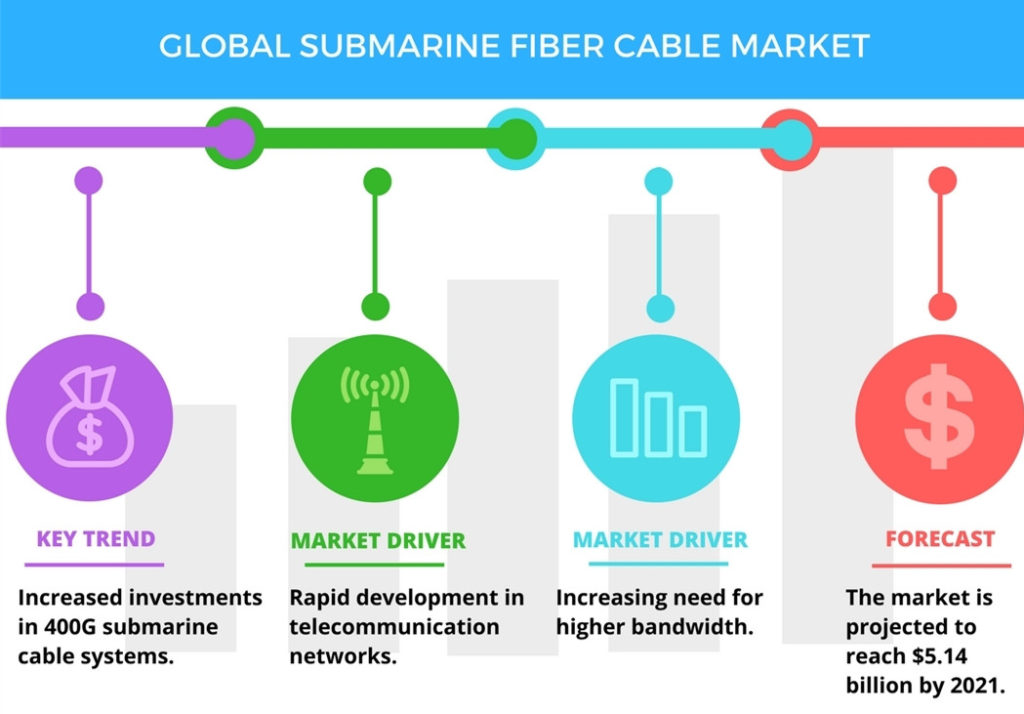
Submarine Optical Fiber Cable Market
Submarine optical fiber cables are undersea cables used for carrying data across interconnected networks between continents. With the advancements of technology, most of the submarine optical fiber cables that currently form the backbone of the Internet connect the U.S. to Europe and Asia by crossing the Atlantic or Pacific oceans. Instead, there is a proposal for deployment of Trans-polar submarine cable system in Arctic Ocean. Laying an undersea fiber optic cable is meant to connect Asia and Europe by crossing the Arctic Circle – the shortest practical distance yet for Internet signals traveling between the two continents. According to the report by Global Industry Analysts (GIA), cumulative installations of submarine optical fiber cables globally are projected to reach 2 million kilometers by 2020, driven by the growing demand for fiber broadband and the ensuing deployment of fiber optic cables in the Internet backbone. Presently, submarine optical fiber cables transmit 100% of the international Internet traffic, and more than 95% of the world’s combined data and voice traffic.
In recent years, the market for optical fiber cable has shifted dramatically to local deployments, away from long haul and regional. This is the impact of FTTx, which calls for far more dense applications in neighborhoods, cities and other highly focused areas. Optical fiber cable is being caught up in the global move to broadband in the near future. The next generation of high bandwidth applications, along with the proliferation of connected devices, is expected to require faster and higher bandwidth networks which will require the use of multimode fiber cable for data transfer. This growth in the FTTx networks in turn is expected to drive the fiber optics market. Future Market Insights (FMI) forecasts the global fiber to the home (FTTH) market’s value will grow from $9.5 billion in 2017 to more than $37 billion by the end of 2027, a 14.4% compound annual growth rate (CAGR). In the leading Asian economies, more than 44% of all homes and buildings are already directly connected to the fiber optic cable network; in North America penetration is 8.4%, in Europe 5.6%.
Final Thought
Fiber optic cable is widely used for data transmission and is increasingly being used in place of metal wires because of its efficiency and high transmission capacity. Since the use and demand for great bandwidth and fast speed, there is no doubt that fiber optic transmission will bring more opportunities and be continuously researched and expanded to cater for future demands. However, although fiber optic cable in itself is considered a long-term stable investment, it also faces huge challenge. The major restraint in the fiber optics market is the growing use of wireless communications systems in remote areas.
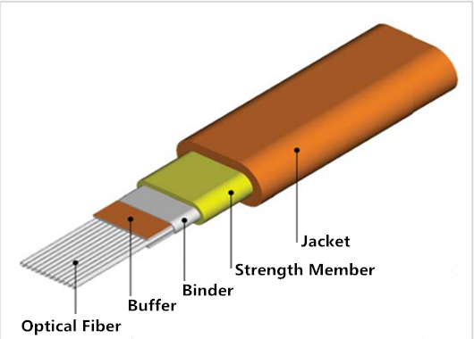
In order to meet the increasing system bandwidth needs, local area network (LAN) campus and building backbones, as well as data center backbones, are migrating to higher cabled fiber counts. Ribbon fiber optic cables can offer the highest fiber density relative to cable size, maximize utilization of pathway and spaces and facilitate ease of termination, which makes them an ideal solution for the need. This post mainly focuses on the benefits and applications of ribbon fiber optic cable.
Ribbon Fiber Optic Cable Design
Ribbon fiber optic cable is a type of cable widely deployed in campus, building and data center backbone applications where high fiber counts are required. There are 8 fibers, 12 fibers, 24 fibers and other higher fiber counts available on the market. At present the 12-fiber ribbons are readily accessible and identifiable with ribbon identification numbers and TIA-598 compliant fiber color coding, which make it prevalent in today’s networks. Usually there are two kinds of outer jacket of ribbon fiber optic cables: non-flame-retardant and formulated flame-retardant. The former is often used in outside plant applications, while the latter is typically used for indoor applications. Here is an example of ribbon fiber optic cable construction.
Benefits of Ribbon Fiber Optic Cable
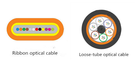
As we all know, stranded loose-tube and ribbon fiber optic cables are staples of the outside plant applications. Both of them perform well in harsh outdoor environments, and both are available in a multitude of configurations, including: all-dielectric, armored, aerial self-supporting, etc. However, when compared to stranded loose-tube cable designs, the ribbon fiber design offers robust performance equivalent to the stranded loose-tube cable, and provides the maximum fiber density relative to cable diameter. The chief distinction between these cables is the manner in which the individual fibers themselves are packaged and managed within the cable. A ribbon fiber cable has the individual fibers precisely bonded together in a matrix that might encompass as few as four or as many as 24 fibers. In contrast, a loose-tube cable has between 2 to 24 individual fibers housed in multiple buffer tubes with each fiber detached from the other.
It’s the special ribbon fiber design that makes ribbon fiber optic cable offer more advantages over loose-tube designs in many applications.
Ribbon fiber optic cable can be prepped and spliced much more rapidly than loose tube cables. That’s means less installation time, less installation labor cost and significantly less emergency restoration time.
Ribbon fiber optic cables enable a smaller footprint in splice closures and telecommunications room fiber management.
Ribbon cables offer greater packing density in higher fiber counts which enables more efficient use of limited duct space.
Ribbon cables are typically very cost competitive in counts above 96 fibers.
Ribbon Fiber Optic Cable Application
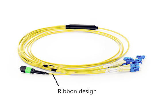
Although there are various fiber counts available with ribbon fiber optic cable, the 12-fiber ribbon cables are the most commonly used ones. With the introduction of innovations such as ribbon splitting tools and field-installable 12-fiber array connectors, 12-fiber ribbons are easily terminated with simplex and duplex connectors such as LC or SC connectors or with the MTP connector. The MTP connector is a 12-fiber push/pull optical connector with a footprint similar to the common simplex connector. Many users like to apply MTP connectors to ensure the highest quality connector insertion loss and return loss performance and to expedite the cable installation.
In order to illustrate how ribbon fiber optic cables are deployed, here take the termination of MTP connectorized ribbon cable with patch panel as an example.
The termination is normally used in an interconnect application where a harness assembly is used on the front of the patch panel. We know the MTP fiber cable has 12-fiber MTP connector on one end of the cable and simplex or duplex style connectors on the other end. Just like the picture below shows.
Except for the application noted above, ribbon fiber optic cables also can be used in both interconnect and cross-connect applications where an MTP connector module cassette is used. And they can be applied to pathways and spaces.
Conclusion
Ribbon fiber optic cables deliver high fiber density in the most compact cable package possible. And they also maximize the number of fibers that can be deployed in a limited space while streamlining fiber termination. At the same time they can save time and money with easy mass fusion splicing. Ribbon fiber cable is now easily obtained using traditional simplex or duplex connectors as well as MTP Connectors, which make them suitable for various applications.
Sensing fiber optic cable is a type of optical cable that can monitor temperature, strain, acoustics and pressure. They are suitable for a wide range of applications like fire detection, vibration monitoring, industrial plant temperature sensing, temperature gradients in soil, pipeline leak and intrusion detection. Although these cables are built based on standard fiber optic cable which only operates to 85℃, the highest working temperature of them is up to 700℃. Before knowing what benefits that sensing fiber optic cable could bring to our life, let’s figure out the common types of sensing optical cable at first.
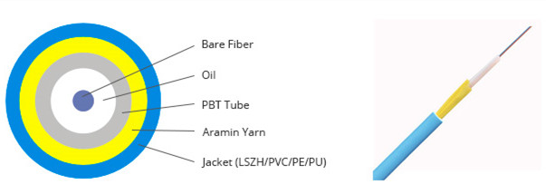
PBT Tube Temperature Sensing Optical Cable
The major difference of this optical cable is that the bare fiber inside is protected by a PBT tube. Except that, it is comprised of fiber, oil, aramid yarn and a sheath which can be made of different materials such as PVC, LSZH, PU and PE. With the unique structure, this sensing fiber optic cable is suitable for applications in subway systems, tunnels and fire protection industries to sense temperature and pressure, helping to prevent disasters and accidents.
Armored Temperature Detecting Sensor Cable
Armored fiber optic cable is very common in optical communication. However, this kind of armored sensing cable is a little different. They are strengthened by both SUS spring tube and SUS braiding, which bring them very good mechanical performance of tensile resistance and pressure resistance. Therefore, these cables are widely applied to fire detecting, building health detecting and temperature detecting.
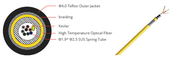
Teflon Sheathed Sensor Cable
Teflon, or PTFE (Poly tetra fluoroethylene) is used in a wide variety of high temperature applications like gas turbine and high voltage gas ignition wires due to its higher melting point. Besides, the aramid yarn and stainless steel braiding ensure good crush-resistant performance and the tensile strength of the cable. With all these characteristics, Teflon sheathed sensor cable is a good choice for high temperature resistant environment and fiber temperature sensing systems.
Seamless Tube Temperature Sensing Cable
This armored fiber optic cable consists of bare fiber, oil, seamless stainless steel tube and an outer jacket. This structure brings a high tensile strength, crush resistance, a compact size and an unmatched steel performance to this fiber cable. And it features a simple structure and small size, but providing prominent transmission performance. With this sensor cable, some accidents that frequently occur in places such as tanks and mines can be avoided.
Copper Braid Armored Sensor Cable
As its name shows, there is a copper braiding around the outer jacket of this sensing cable. Copper braid is made from weaving together strands of copper wire. The flexibility of the braid is determined by the diameter of the copper wire. The smaller the wire, the greater the flexibility. And the larger the volume occupied by the braid, the more expensive the braid becomes. Apart from the copper braiding, there are stainless steel flexible tube and stainless steel braiding outside the bare fiber, which make the cable more suitable for outdoor optical fiber communication and optical fiber sensor. With the copper braiding structure, the special cable can prevent the external electromagnetic field on internal invasion, reducing its optical transmission loss.
Silica Gel Sensing Optical Cable
Unlike copper braid armored sensor cable, the silica gel sensing optical cable has a very simple structure, including bare fiber, Teflon tube, armored yarn and silicone jacket. As have mentioned above, Teflon is a high performance alternative insulation. With the silica gel that is another kind of good insulation material, both of them make this sensing fiber optic cable an ideal solution for high temperature resistant and high voltage environment. It can work normally even in the 250℃ high temperature environment or 6kv high voltage environment without affecting optical signals’ transmission.
Summary
The deployment of sensing fiber optic cables brings us lots of benefits in various applications. They can be applied in downhole to monitor temperatures either as DTS or datacom links to sensors; they can be deployed in power distribution networks to monitor performance of power cable systems; they can be attached to pipelines for temperature data that’s available on demand. This post introduces six kinds of sensing fiber optic cable. All of them are available on FS.COM. Welcome to contact us via sales@fs.com.
As a perfect choice for today’s telecommunication which requires a larger bandwidth, fiber optic cables have been widely put into use and get more popularity. However, when optical cables are increasingly used in different applications with diverse environments, for example, from indoor to tough environments, new and demanding requirements also have been put forward for them. Before deployment, several considerations may occur. For instance, can they resist the erosion of oil or chemicals? Can they still work normally in changeable weather? Do they have rodent-resistant ability? The answer of all the questions is yes. Today’s fiber optic cables possess various abilities to meet different requirements. Here is a brief introduction several ruggedized fiber optic cables that can work in different harsh environments, providing more conveniences and extra protection for network systems.
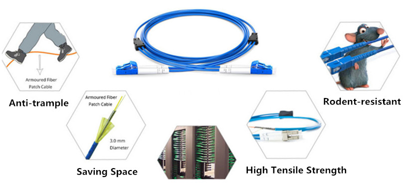
Armored Fiber Optic Cable
Armored fiber optic cable is one of the most commonly used cables to offer protection for fibers. Generally, armored fiber optic cable contains a helical stainless steel tap over a buffered fiber surrounded by a layer of aramid and stainless steel mesh with an outer jacket. With this unique construction, it can withstand the toughest environments—high temperatures, high pressures, and harsh vibrations as well as animals rodent and moisture. In a word, with the protection of flexible and durable steel tube, armored fiber patch cable will ensure the excellent operation of networks.
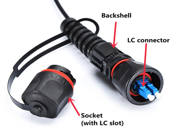
IP67 Waterproof Fiber Optic Cable
IP67 waterproof fiber optic cable is another kind of ruggedized cables used for outdoor applications. They are with strong PU jacket and stainless steel armor inside for future protection. “IP” in this term is a type of protection rating defined by International Standard IEC 60529. The number “6” and “7” mean this kind of cable possesses a good ability to resist dust and water. According to the connector types, the IP67 waterproof fiber optic cables have several types including IP67 MTP/MPO fiber cables, IP67 LC waterproof fiber cable and so on. IP67 waterproof fiber optic cables will not get damage even stepped, and are anti-rodents and suitable for use in harsh environment like communication towers and CATV (Community Antenna Television), providing protection for your networks. Here is a picture of IP67 LC component details.
Summary
With the rapid development of optical communication around the world, more and more fiber optic cables are increasingly used in different environments. Under harsh conditions, the ruggedness and durability of common fiber optic cables cannot meet operators’ requirements, especially for exceptional demanding applications. This post mainly introduces three types of ruggedized fiber optic cable. All the cables mentioned above are available in FS.com. If you have any problems about them, please contact us via sales@fs.com.
Bend insensitive multimode fiber (BIMMF) has become a very active area within the telecommunication industry once it was introduced and popularized. It typically signifies technical advancements in the production of multimode optical fiber for easier installation, and cable management for multimode fiber cables through improvements in bend insensitivity. This article will focus on some useful information about BIMMF from the perspective of its working principle, performance in networking and unique advantages as well.
What Is Bend Insensitivity?
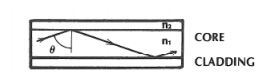
An optical fiber consists of a core and a cladding. Although both of these regions are made from glass in telecommunications grade fibers, they are significantly different from each other. Each region is designed to capture light within the core and transmit it to the opposite end of the fiber. During this process, the light may follow many paths, depending on the angle at which the light hits the boundary, it is either reflected back into the core, or it gets lost into the cladding. Therefore, the light losses during transmission cause a weaker optical signal at the other end.
Optical fiber is sensitive to stress, particularly bending. When conventional fibers are bent tightly, some of the signal will leak out of the fiber at the site of the bend due to macrobend loss, which will results in system failure and unplanned downtime. Various attributes in the fiber determine when this occurs. The relative ease with which this happens is known as bend sensitivity. On the contrary, bend insensitivity is a positive feature that can provide for additional robustness and simplify installation of multimode fiber.
Introduction to Bend Insensitive Multimode Fiber (BIMMF)
Bend-insensitive multimode fiber (BIMMF) has an innovative core design that enables it to significantly reduce macrobend loss even in the most challenging bend scenarios. It is hence natural that bend insensitive multimode fiber can withstand tough treatment. The difference between traditional multimode fiber and BIMMF mainly lies in the fact that the BIMMF design can include an optical trench. This trench effectively improves the fiber’s macrobend performance by retaining more of the light that would have escaped the core of a traditional multimode fiber. So when compared with standard multimode fibers, BIMMF is proved to be a good candidate for loss and bend critical applications because of their higher immunity to bending losses, without loosing performances or compatibility to other standard high bandwidth multimode fibers.
Compatibility With Conventional Fibers
There is a lot of buzz around the issue of bend insensitive fiber— is it compatible with regular fibers? Can they be spliced or connected to other conventional fibers without problems? Modeling and testing on BIMMF has shown that an optimized BIMMF is backward compatible and can be mixed with non-BIMMF without inducing excess loss. Hence, BIMMF and MMF could easily be mixed in an optical channel without complicating the estimation of losses. Moreover, BIMMF may lead to higher tolerance to possible misalignments when two connectors are mated. This is an additional positive feature for 40 and 100 Gigabit applications.
In summary, a well-designed BIMMF complies with all relevant industry standards and adheres to the following:
BIMMF OM2, OM3 and OM4 multimode fibers are fully compliant and fully backward-compatible with all relevant industry standards.
BIMMF is fully backward-compatible and may be used with the existing installed base of 50/125um multimode grades including OM2, OM3 and OM4.
BIMMF may be spliced or connectorized to conventional 50/125um fiber types with commercially available equipment and established practices and methods, no special tools or procedures are required.
BIMMF not only meets all relevant macrobend standards, but sets a new level of bend performance.
Advantages of BIMMF
Bend insensitive multimode fiber is available in all laser optimized grades, OM2, OM3 and OM4, and exhibits 10 times less signal loss in tight bend scenarios and therefore protects enterprise and data center systems from unplanned downtime due to signal loss and associated significant revenue loss.
This fiber type offers extremely low bending loss at both the 850 and 1300 nm operating windows, while maintaining excellent long term fiber strength and reliability. The fiber can be installed in loops as small as 7.5 mm radius with less than 0.2 dB bending loss at 850 nm and 0.5 dB at 1300 nm.
Maximum induced bend loss performance at 850 nm
Standard for multimode fibers IEC 60793-2-10
Bend Insensitive MMF (no standard currently)
Bend radius
37.5 mm
7.5 mm
Number of turns
100
2
Conventional MMF
0.5 dB
–
Bend Insensitive MMF
0.05 dB
0.2 dB
In addition, bend insensitive multimode fibers enable new possibilities for cable and patch panel design to further improve the benefits of using fiber. Optical cable manufacturers can now design thinner, more flexible trunk cables, making for easier cable installation and further improving airflow in conduits, patch panels and racks. Due to the ability of the fib cable to be bent tightly with significantly less signal loss, connector modules can be made smaller which in turn leads to an increased density within racks and smaller racks.
Conclusion
Bend insensitive multimode fiber has been widely employed to enhance fiber management in data centers, high performance computing and enterprise LANs. Since it is a real advance to current standard multimode fibers, BIMMF is recommended for bend and loss critical applications. What should be noticed is that BIMMF also should be handled with appropriate care as all optical glass fibers.
Contaminated fiber optic cables can often lead to degraded network performance or even failure of the whole system. As such, to ensure that fiber optic cables can yield the best possible results of network performance, and it’s of great significance for network engineers to keep in mind how to handle fiber optic cables. Do you have any ideas? This text gives the guide to fiber optic cable handling rues.
Fiber Optic Cable Elements
Before delving into how to handle fiber optic cables, introduction to their makeup elements is required.
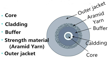
Fiber optic cable generally consists of fiver elements (figure shown above): the optic core, optic cladding, a buffer material, a strength material and the outer jacket. Commonly made from doped silica (glass), the optic core is the light-carrying element at the center of the cable. Surrounding the core is the optic cladding, whose combination with the core makes the principle of total internal reflection possible. Surrounding the cladding is a buffer material used to help shield the core and cladding from damage. A strength material surrounds the buffer, preventing stretch problems when the fiber cable is being pulled. The outer jacket is added to protect against abrasion, solvents, and other contaminants.
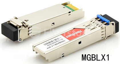
The outer jacket on fiber optic patch cord is often color-coded to indicate the fiber types being used. For instance, multi-mode fiber (MMF) is usually in orange to distinguish from the color yellow for single-mode fiber (SMF) through which fiber optic transceivers realize relatively long distance, such as MGBLX1. This Cisco 1000BASE-LX SFP transceiver is able to achieve 10km link length over SMF.
Fiber Optic Cable Handling Rules
Despite its outer protection mentioned above, fiber optic cable is still prone to damage. In such as case, a series of fiber cable handing rules are made to ensure that a cable is handled properly, so as to maintain the optimized performance, minimum insertion loss and safe working environments.
Rule 1: The exposed fiber end from coming in contact with all surfaces should be protected. If you contact the fiber with hard surfaces, then the end of it shall be scratched or chipped, causing the degraded performance.
Rule 2: It’s highly recommenced to lean the connector (plug) end each time it is inserted into an adapter, since since a dirty connector will contaminate an adapter.
Rule 3: If a fiber needs to be pulled, use the connector strain relief. Directly pulling on the fiber may result in the glass breaking.
Rule 4: It’s ill-advised to use your hands to clean a fiber work area. If you use your hands to wipe clean a work area, a piece of glass may get lodged into your hands. Considering the size of the glass, this glass may not be visible to the naked eye, bringing about eye damage.
Rule 5: If possible, always keep a protective cap on unplugged fiber connectors, because covering the adapters and connectors will help to avoid contamination and collection of residue. Besides, store unused protective caps in a resealable container in order to prevent the possibility of the transfer of dust to the fiber. Locate the containers near the connectors for easy access.
Rule 6: It’s suggestible to use fiber-cleaning materials only once. If optic grade wipes are used to clean the fiber end, they should be discarded immediately after the fiber surface has been wiped to avoid contamination.
Rule 7: The minimum bend radius of the fiber optic cable must be maintained. Surpassing the bend radius may cause the glass to fracture inside the fiber optic cable. Equally, to cause a twist of the cable is also not proposed.
Rule 8: Never look into a fiber while the system lasers are on. Eye damage may occur if you stare directly at a fiber end which is working. Always make sure that the fiber optic cables are disconnected from the laser source, prior to inspection.
After discussion, these handling rules may help you to deal with fiber optic cables and improve your network performance.
Conclusion
Proper handling procedures for fiber optic cables are needed to eliminate the possibility of being contaminated or damaged, and provide a clean environment for the network system. Fiberstore supplies many different types of fiber optic cables with high quality for various applications, like MTP cable. You can visit Fiberstore for more information about fiber optic cables.