Choosing the Right MTP/MPO Cable: A Guide to Core Numbers

Choosing the right MTP/MPO cable ensures efficient and reliable data transmission in today’s fast-paced digital world. With the increasing demand for high-speed connectivity, it is essential to understand the importance of core numbers in MTP/MPO cables. In this guide, we will explore the significance of core numbers and provide valuable insights to help you decide when selecting the right MTP/MPO cable for your specific needs. Whether setting up a data center or upgrading your existing network infrastructure, this article will serve as a comprehensive resource to assist you in choosing the right MTP/MPO cable.

What is an MTP/MPO cable

An MTP/MPO cable is a high-density fiber optic cable that is commonly used in data centers and telecommunications networks. It is designed to provide a quick and efficient way to connect multiple fibers in a single connector.

MPO and MTP cables have many attributes in common, which is why both are so popular. The key defining characteristic is that these cables have pre-terminated fibers with standardized connectors. While other fiber optic cables have to be painstakingly arrayed and installed at each node in a data center, these cables are practically plug-and-play. To have that convenience while still providing the highest levels of performance makes them a top choice for many data center applications.

How Many Types of MTP/MPO cables

MTP/MPO cables consist of connectors and optical fibers ready to connect. When it comes to types, MTP/MPO fiber cables fall on MTP/MPO trunk cables and MTP/MPO harness/breakout cables.

MTP/MPO trunk cables

MTP/MPO trunk cables, typically used for creating backbone and horizontal interconnections, have an MTP/MPO connector on both ends and are available from 8 fibers up to 48 in one cable.

MTP/MPO Harness/Breakout Cables

Harness/Breakout cables are used to break out the MTP/MPO connector into individual connectors, allowing for easy connection to equipment. MTP/MPO conversion cables are used to convert between different connector types, such as MTP to LC or MTP to SC.

The MTP/MPO cables also come in different configurations, such as 8-core, 12-core, 16-core, 32-core, and more, depending on the specific needs of the application. This flexibility in configurations enables users to tailor their choices according to the scale and performance requirements of their networks or data centers. As technology advances, the configurations of MTP/MPO cables continually evolve to meet the increasing demands of data transmission.

How to Choose MTP/MPO cables

Selecting the appropriate core number for MTP/MPO cables resonates throughout the efficiency and performance of networks. In this section, we’ll delve into the decision-making factors surrounding core numbers in cables.

Network Requirements and Data Transmission Goals

Different network applications and data transmission needs may require varying numbers of cores. High-density data centers might necessitate more cores to support large-capacity data transmission, while smaller networks may require fewer cores.

Compatibility with Existing Infrastructure

When choosing the core number for MTP/MPO cables, compatibility with existing infrastructure is crucial. Ensuring that the new cables match existing fiber optic equipment and connectors helps avoid unnecessary compatibility issues.

Consideration for Future Scalability

As businesses grow and technology advances, future network demands may increase. Choosing MTP/MPO cables with a larger number of cores allows for future expansion and upgrades.

Budget and Resource Constraints

Budget and resources also play a role in core number selection. Cables with a larger number of cores tend to be more expensive, while cables with fewer cores may be more cost-effective. Therefore, finding a balance between actual requirements and the available budget is essential.

MTP/MPO Cabling Guide to Core Numbers

40G MTP/MPO Cabling

A 12-fiber MTP/MPO connector interface can accommodate 40G, which is usually used in a 40G data center. The typical implementations of MTP/MPO plug-and-play systems split a 12-fiber trunk into six channels that run up to 10 Gigabit Ethernet (depending on the length of the cable). 40G system uses a 12-fiber trunk to create a Tx/Rx link, dedicating 4 fibers for 10G each of upstream transmit, and 4 fibers for 10G each of downstream receive.

40G-10G Connection

In this scenario, a 40G QSFP+ port on the FS S5850 48S6Q switch is split up into 4 10G channels. An 8-fiber MTP-LC harness cable connects the 40G side with its MTP connector and the four LC connectors link with the 10G side.

40G-40G Connection

As shown below, a 12-fiber MTP trunk cable is used to connect two 40G optical transceivers to realize the 40G to 40G connection between the two switches. The connection method can also be applied to a 100G-100G connection.

40G Trunk Cabling

24 Fibers MTP® to MTP® Interconnect Conversion Harness Cable is designed to provide a more flexible multi-fiber cabling system based on MTP® products. Unlike MTP® harness cable, MTP® conversion cables are terminated with MTP® connectors on both ends and can provide more possibilities for the existing 24-fiber cabling system. The 40/100G MTP® conversion cables eliminate the wasted fibers in the current 40G transmission and upcoming 100G transmission. Compared to purchasing and installing separate conversion cassettes, using MTP® conversion cables is a more cost-effective and lower-loss option.

100G MTP/MPO Cabling

QSFP28 100G transceivers using 4 fiber pairs have an MTP/MPO 12f port (with 4 unused fibers). Transmission for short distances (up to 100m) could be done most cost-effectively over multimode fiber using SR4 transmission. Longer distances over single mode use PSM4 transmission over 8 fibers. Transmission over 4 fiber pairs enables both multimode and single-mode transceivers to be connected 1:4 using MPO-LC 8 fiber breakout cables. One QSFP28 100G can connect to four SFP28 25G transceivers.

100G SR4 Parallel BASE-8 over Multimode Fibre

QSFP28 100G SR4 are often connected directly together due to their proximity within switching areas.

Equally QSFP28 SR4 are often connected directly to SFP28 25G ports within the same rack. For example, from a switch 100G port to four different servers with 25G ports.

The 12-core MTP/MPO cables can also be used for 100G parallel to parallel connection. Through the use of MTP patch panels, network reliability is enhanced, ensuring the normal operation of other channels even if a particular channel experiences a failure. Additionally, by increasing the number of parallel channels, it can meet the continuously growing data demands. This flexibility is crucial for adapting to future network expansions.

100G PMS4 Parallel BASE-8 over Singmode Fibre

QSFP28 100G PMS4 are often connected directly together due to their proximity within switching areas.

Equally QSFP28 ports are often connected directly to SFP28 25G ports within the same rack. For example, from a switch 100G port to four different servers with 25G ports.

200G MTP/MPO Cabling

Although most equipment manufacturers (Cisco, Juniper, Arista, etc) are bypassing 200G and jumping from 100G to 400G, there are still some 200G QSFP-DD transceivers on the market, like FS QSFP56-SR4-200G and QSFP-FR4-200G.

200G-to-200G links

MTP (MPO) 12 fiber enables the connection of 2xQSFP56-SR4-200G to each other.

400G MTP/MPO Cabling

MTP/MPO cables with multi-core connectors are used for optical transceiver connection. There are 4 different types of application scenarios for 400G MTP/MPO cables. Common MTP/MPO patch cables include 8-fiber, 12-core, and 16-core. 8-core or 12-core MTP/MPO single-mode fiber patch cable is usually used to complete the direct connection of two 400G-DR4 optical transceivers. 16-core MTP/MPO fiber patch cable can be used to connect 400G-SR8 optical transceivers to 200G QSFP56 SR4 optical transceivers, and can also be used to connect 400G-8x50G to 400G-4x100G transceivers. The 8-core MTP to 4-core LC duplex fiber patch cable is used to connect the 400G-DR4 optical transceiver with a 100G-DR optical transceiver.

For more specific 400G connectivity solutions, please refer to FS 400G MTP/MPO Cabling.

800G MTP/MPO Cabling Guide

In the higher-speed 800G networking landscape, the high density, high bandwidth, and flexibility of MTP/MPO cables have played a crucial role. Leveraging various branching or direct connection schemes, MTP/MPO cables are seamlessly connected to 800G optical modules, 400G optical modules, and 100G optical modules, enhancing the richness and flexibility of network construction.

800G Connectivity with Direct Connect Cabling

16 Fibers MTP® trunk cable is designed for 800G QSFP-DD/OSFP DR8 and 800G OSFP XDR8 optics direct connection and supporting 800G transmission for Hyperscale Data Center.

800G to 8X100G Interconnect

16 fibers MTP®-LC breakout cables are optimized for 800G OSFP XDR8 to 100G QSFP28 FR, 800G QSFP-DD/OSFP DR8 to 100G QSFP28 DR optics direct connection, and high-density data center applications.

800G to 2X400G Interconnect

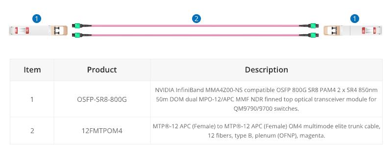
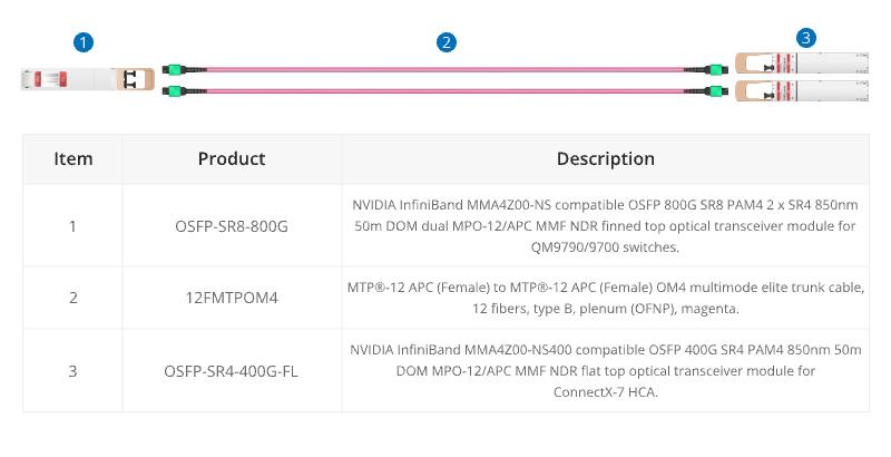
16 fiber MTP® conversion cable is designed to provide a more flexible multi-fiber cabling system based on MTP® products. Compared to purchasing and installing separate conversion cassettes, using MTP® conversion cables is a more cost-effective and lower-loss option. In the network upgrade from 400G to 800G, the ability to directly connect an 800G optical module and two 400G optical modules provides a more efficient use of cabling space, resulting in cost savings for cabling.

Conclusion

In a word, the choice of core number for MTP/MPO cables depends on the specific requirements of the network application. Matching the core number with the requirements of each scenario ensures optimal performance and efficient resource utilization. A well-informed choice ensures that your MTP/MPO cable not only meets but exceeds the demands of your evolving connectivity requirements.

How FS Can Help

As a global leader in enterprise-level ICT solutions, FS not only offers a variety of MTP/MPO cables but also customizes exclusive MTP/MPO cabling solutions based on your requirements, helping your data center network achieve a smooth upgrade. In the era of rapid growth in network data, the time has come to make a choice – FS escorts your data center upgrade. Register as an FS website member and enjoy free technical support.

Tutorial- How To Assemble a Fiber Optic Connector

Because there are many different types of fiber optic connectors have been developed, we will talk about fiber optic connectors in fairly general terms.

Most popular connectors in use today have some common elements. Let’s examine it below:

The most critical part, fiber is installed, is the ferrule. Ferrule is long, thin cylinder with the fiber mounted in the center hole. The size of the center hole is set to match the cladding of the fiber is usually 125 microns in diameter.

Fiber connector ferrules are made from several types of materials including ceramic (Zirconia), stainless steel and plastic.

The ferrule’s work is the center and align the fiber and protects it from mechanical damage. Finally at the end of the fiber ring and fiber end is polished smooth either flat or curvature.

The ferrule is mounted in the connector body and then the connector body is attached to the fiber optical cable structure. Finally, a strain-relief rubber boot protects the connector cable junction.

Unlike most electronic connectors, fiber optic connectors usually do not have the male-female polarity. Most fiber connectors are male only. Instead, fiber optic connectors to mate in the fiber optic adapter, it is often referred to as mating sleeves or coupling socket. Fiber optic adapter connector types used in different partners such as FC SC connector connector is called hybrid adapters.

Although this method needs to use a separate adapter, fiber optic connector it otherwise to reduce inventory requirements because now you only need to stock a type connector. Another advantage is that fiber optic adapters can be designed to mate one type of connector to another, which is a big plus compared to electronic connectors.

The fiber’s plastic coating is stripped first before the fiber is inserted in the ferrule. The center hole through the ferrule is large enough to fit the fiber cladding (which is usually 125um after fiber coating stripped off) but tight enough to hold the fiber in a fixed position without any further moving.

Standard bore diameters are 126 +1/-0 um for single mode connectors and 127 +2/-0 um for multimode connectors. Because of fiber cladding diameter’s variation from manufacturing, some fiber connector manufacturers also supply a range of ferrule bore sizes such as 124um, 125um, 126um and 127um.

Fiber optic epoxy or adhesive is inkected into the ferrule hole before the fiber is pushed in to hold the fiber in place. The epoxy or adhesive is then cured with high temperature oven according to adhesive manufacturer’s instruction. Finally the fiber end is polished to a smooth face on polishing films.

The ferrule is then slipped inside another hollow cylinder before it is mounted in the connector body. The connector body includes one or more pieces that are assembled to hold the cable and fiber in place. Connector body is made of metal or plastic.

The ferrule end protrudes beyond the connector body so it can slip into the mating sleeves (fiber adapters). A stain relief rubber boot is finally slipped over the cable end of the connector to protect the cable connector junction point.

In fiber optical cross connect boxes or fiber patch panels, an array of connector adpators are mounted inside, ready for you to plug an input fiber cable in one side and an output cable in the other. Fiber connector adapters are also mounted in wall outlets, just like standard phone jacket.

How Do Fiber Optics and Cable Television Work

Fiber optical cable and the old common (RF or coaxial) cabke are two different cable system technologies that can be used to distribute various services to end users-homes. In general, they differ only in technical (electrical or communication) point of view. This is mainly important for the network operators because end users or viewers don’t care about the technology, they are insterested in services and TV channels.

There are serveral different methods that can be used to release public services like television channel through a cable television network. Each has some advantages and disadvantages and require different topology structure and network infrastructure.

Analog Television

The first cable television network was just extension of the broadcast in the air. This was implemented by deploying ordinary antenna cable (but with lower losses) from the cable system headend to the homes. Because of distance and many amplifier at a particular point, to ensure that the required signal level. Special communication is one-way, but then most of these cable network to expand to DocSys allows two-way communication need to access the Internet through the use of the system.

This approach can be used with radio frequency coaxial and optical fiber cable. Fiber optic cables are also used in some cases to distribute the old analog cable television. The advantage of optical network because it can use the available fiber in the existing optical fiber cable and the cable loss is very low.

Digital Television

Digital television in cable networks can be divided into two totally different ways of distribution. The first one is an equivalent to digital broadcasting and the other way mainly used in fiber optic networks is IP television.

Digital Cable Broadcastingn

This is equivalent to analog distribution over (RF) cable but with digital signal. The same technology (modulation) can be used as the ground broadcasting but usually, there are more efficient systems, considering the specific properties of the cable system. One typical example is DVB-T system which is used in Europe for digital terrestrial video broadcasting but cables use similar DVB-C system.

IP Television

This is one of the most popular digital television distribution used with fiber optic cable systems. This means that the distribution channels with IP protocol is the backbone of network communication. Each TV channels is encoded with either MPEG-2 or MPEG-4 system and then distributed over fiber optical cable network to the homes. The advantages are enormous. The capacity for the number of channels is pretty high, all the channles can be encoded and distributed with very high quality, it is very easy to distribute HD channels, access to the internet is very simple because of the IP protocol and native technology.

Regardless of distribution cable technology the changes are also happening in the consumer industry. The old CRT television sets are replaced by plasma or LCD flat panel displays and aspect ratio or picture format is also changing from 4:3 to 16:9. Since computer LCD monitors use similar display panels they can be converted to televisions by just adding a simple TV tuner.

The Industrial Purpose of Using Fiber Optic Cables

There are several kinds of industrial applications through the use of fiber optical cable. Thin fiber of glass or plastic, through which data can light and sound propagation is called optical fiber. These optical fibers as thin as human hair. When they are assembled together, they form a cable that can be used for transmitting information and signals.

Optical fiber is widely used in telephone and telecom industry. Optical lighting is also an indispensable medical, aerospace and military applications. Other systems such as intrusion detection alerts or light through optical fiber movements. Thanks to their big data carrying capacity, the cable is particularly important in the local area network (LAN). Applications such as machine vision lighting are enabled via optical lightings.

A major advantage of these cables is proposed is their lower cost than the traditional use of copper wire. Here are some other offers important advantages of fiber optic cable:

Long-distance data transmission

High bandwidth can be reach even over long distances using this cable. They can carry critical signals without the loss of data. These cables also do not get jammed, making them ideal for mission critical operations such as sending flight signals.

Immune to electromagnetic interference

Since these cables use the medium of light, and not electricty, to transmit signals, electromagnetic interference doesn’t usually affect the data transmission process.

The ideal security data transmission

It is a known fact that electromagnetic interference (EMI) could also cause data leaks. This is a potential threat for sensitive data transfer operations. It may not always be possible to shield the wire, and even with the shielding, also cannot guarantee 100% safety. On the contrary, an optical cable has no external magnetic field so signal tapping is not easily achieved. This makes an optical cable is the most preferred components or sensitive data transmission security.

No spark hazard

Electrical wiring constantly needs to be safeguarded against a potential spark hazard. This isn’t the case with optical fiber cables as they are inherently safe. This particular attribute is especially significant in industries such as chemical processing or oil refineries where the risk of explosion is high. Signals that are sent using cables do not spark.

No heat issues

Fiber optics can carry small amounts of light without the risk of producing heat. Thus, fiber optic cables are safe to use in surgical probes that are inserted inside a patient’s body to study internal organs. These very cables are also used during surgeries to relay laser pulses. With no heat or shock hazard, such cables are safe to use during the most critical surgeries. This attribute makes optical cables safe for use in machine vision lighting applications too.

These are a few fundamental advantages of optical cables. There are several other benefits that a professional optical cable manufacturing house shall be able to discuss with you. More information about products such as LSZH cable, armored fiber cable for all you industrial applications.

Source: www.fs.com

Show You How to Install Outdoor Fiber Optic Cable In Underground Ducts

Fiber ducts are usually made of HDPE (high density polyethylence), PVC or other compound. They are usually in black or gray. Fiber innerduct is usually orange or yellow.

Why usually fiber ducts and innerducts are corrugated?

Fiber ducts and innerducts are corrugated to provide the following benefits:

1. During the installation to reduce the traction tension;

2. Very flexible and can be used to install location involves many times;

3. After installation, corrugated innerduct should place one day allow innerduct retreat back into the duct through its waveform spring action.

The use of pulling tape

Fiber optic cable traction tape is pre-installed in the fiber duct and innerduct in the factory. This saves a lot of time during the installation process. Duct and innerduct can also be prelubricated in the factory, thus significantly reduces pulling tensions.

Never bend over its minimum bend radius

Like a fiber optic cable, fiber duct and innerduct also have a minimum bending radius specification. Always should be bent pipe or innerduct tightening than its minimum bending radius.

What is supported and unsupported radius?

The supported radius is the minimum bend radius when the duct is bent around a supporting structure such as in another duct or on a reel. The unsupported radius is the minimum bend radius when the duct has no supporting structure in the bend.

Benefits of using fiber duct and innerduct

Fiber duct- Fiber duct protects the fiber cables and also provides an opportunity for future cable access and expansion. Fiber optic cable can be pulling into existing duct. The duct should usually be oversized to allow future cables be pulled in.

Fiber innerduct- Fiber innerduct of fiber optic cable to provide protection from the other company of cable installation. It also provides additional protection of the environment. Innerduct or fiber can be used in the old pipe installation.

Things to keep in mind

1. Install the end plug

After the fiber optical cable is installed into a duct or innerduct, end plugs should be installed to provide a water seal. No pieces should be able to enter the duct or innerduct, and watertight should always be maintained for the duct or innerduct.

2. Duct and innerduct should be properly sized for future expansion possibility

As usual, the expansion of the plan for the future project is crucial to the success of the real. The ration of up to 40% is a good practice to fill the following. Should increase the length of pipe size is the length of installed with many times. A larger pipe can help reduce the tension in the cable drawing. 3 to 8 inches standard pipe sizes in different ID and innerduct size range from 0.75 to 2 inches.

The benefit of using duct lubricant

Duct lubricant can significantly reduce the cable’s coefficient of friction, thus lessening the pulling tension during cable pulling process. This is especially important in long duct cable pulls with many turns.

Duct lubricant spillage should be cleaned up as soon as possible to prevent accident since it is very slippery. Manufactures’ recommended procedure for cleaning lubricant provides good instruction on how to do the cleaning.

How To Choose Ribbon Fiber

Do you know why it is so costly to install the optical fiber to the home? Bell why reluctant to deploy fiber optic network directly to consumers in a large sacle? This is not the cost of materials. It’s the labor! The introduction of fiber into the subscriber loop has increased the installation of short cable lengths with large number of splices. The cable speeds can be placed, splicing, access, and reconfigure the becomes very important.

So the need for new technologies that promise to reduce the fiber deployment cost are very high. Bell company is anxious in the acquisition of these new technologies and products, in order to reduce their costs and promoting broadband fiber optic network installation.

That is where the high fiber count ribbon cables come to play. These compact, UV bonded epoxy cable is composed of high precision optical fiber, can centralized fusion splicing with minimal losses. These products have been proved to be an excellent platform for deployment of optical fiber to the home.

Massive fusion splicing machine from Japanese companies are a integrated part of this process. These fusion splicers using optical fiber installation technicians 24 fibers splicing in the time and very low couping loss.

Ribbion Fiber Design: The most basic requirement for any fiber optical cable design is to protect the glass fiber from the harsh environment. But for ribbon fiber, there is the other vital requirements: best space efficiency and easy to mass organization fiber fusion splicing and processing. And at the same, they must also be able to keep the optical performance and mechanical reliability.

This means that ribbon fiber optic cable must pack high count of glass fibers, organize fibers precisely for mass fusion splicing, provide individual fiber identification, can be divided into single fibers or subunits, mechanically reliable and can be easily accessed from the end or midspan. These requirements must all be met at the same time which makes the manufacturing of high quality ribbon fibers a tough task.

So fiber optic cable experts concluded that an excellent design. A color coded array of fibers bonded in a line with fiber coating material. Based on this fundamental structure, two designed emerged: edge bonded or encapsulated.

Edge Bonded Design: The Edge bonded design basically bonds the fibers together with only materials in between of each fiber. This design is more popular in the United States. This design is 40% less than the encapsulated design.

Encapsulate Design: In packaging design, bonding material is more than the gaps between the fibers, it encapsulates all the fibers in a rectangular tube look. This design is more used in Japan.

Ribbon Fiber Mass Fusion Splicing

The time saving for ribbon fiber mass fusion splicing are so big that sometimes in the field individual fibers are ribbonlized to make mass fusion splicings. However, the success of mass ribbon fiber splicing relies critically on the fiber geometry, the ribbon and the mass fusion splicer. High quality and consistent mass fusion splices can only be produced with ribbons that are made from fibers having stringent geometric tolerances. These high quality fibers and ribbons are already commercially available. And they make the fiber deployment in FTTH projects a joy for the installers.

How To Distinguish Between Good or Bad The Quality of Fiber Optic Cable

1. Ointment. Ointment is mainly fine paste paste with cable, fiber paste normally should be full of the casing, cable paste should be under pressure every crevice of cable core. Now, fiber paste sufficient half-full or less the practice of cable extract some just wipe a layer of the cable core, while others are in the middle of the fiber optical cable two charge is not sufficient. This will make the fiber are not good protection, the impact of the transmission performance of optical fiber attenuation, poor water resistance less than the national standard, once the cable accidental seepage will cause the whole links seepage scrapped. Under normal circumstances, even accidental seepage simply repair a section of water seepage can, you do not need to start over. (National standard water-blocking performance: three meters of fiber optic cable, one meter of water column pressure round the clock impermeable.) If use poor ointment will also appear to be happening, and may because the ointment thixotropic, cause the fiber to cause microbending loss, the link transmission characteristics failed; ointment with acidic also with fiber optic cable metal materials analysis H reaction precipitation of hydrogen molecules, fiber case of H decay will increase dramatically, resulting in the entire link interrupt transmission.

2. Sheath. The cable sheath is necessary to adapt to many different complex climate, but also to ensure the stability of the long-term (at least 25 years). Cable jacket not only have a certain strength, low thermal deformation, wear, water permeability, heat-recoverable, and coefficient of friction, but also should be strong resistance to environmental performance materials processing features. Less or bad sheath material cracking, water seepage through factory acceptance, but the quality is defective use for some time, using recycled plastics to replace quality polyethylene sheath material is more serious. High quality sheath material made of fibe optic cable, a cable skin smooth, bright, uniform thickness, no bubbles, otherwise the coarse skin of fiber optic cable, and a lot of very small pit, and because of the thin thickness, the entire outer diameter of the fiber optic cable will be muach smaller than the high quality cable. Indoor fiber optic cable, usually made of high quality flame retardant PVC, the appearance should be smooth, bright, good flexibility, easy to peel; and otherwise poor skin finish, easy and tight buffer fiber, aramid adhesion phenomenon.

3. Steel, aluminum. Steel, aluminum cable is mainly used to protect the fiber from mechanical side pressure, moisture and other effects, better cable typically use chrome-plated steel strip. Low quality fiber optic cable to only one side done ordinary iron rust treatment, or black (uncoated steel), instead of chrome-plated steel strip, over time, the cable will appear corroded, fiber optic hydrogen loss also aggravate andits easy separation do not constitute the sheath bonded sheath tide also very poor performance; of some places tinned strip instead of chrome-plated steel strip, tin-plated surface of the strip, the bubble is inevitable, so in humid, prone to corrosion under the conditions of the atmosphere and surface condensation or water, especially under acidic conditions, corrosion faster. The tin plating layer is poor in heat resistance, melting at 232 degrees Celsius, only the application of due to squeeze sheaths when the high temperature, such that the peel strength uncertainty affect the cable anti-surge performance. Chromium melting point of 1900 degrees Celsius, chemically very stable at room temperature in air or water will not rust, corrosion resistance, very good resistance to environmental performance, easily oxidized due to surface passivation layer is formed so good. Aluminum generally failed thermal paste method coated aluminum instead of cast qualified coated aluminum, which also affect cable performance.

4. Steel wire. The steel wire in the fiber optic cable mainly used to protect optical fiber from the mechanical tension. Good cable typically use for phosphating steel wire, high modulus short-term tension 1500N and 3000N. And low-quality fiber optic cable will be a very small diameter wire or ordinary steel instead of the one hand, easy to rust; On the other hand, is far less than the tensile strength 1500N construction may strain the fiber. High modulus phosphide stell wire is generally gray color, good toughness, not easy to bend; the alternative wire generally pinch in your hand can be bent a long time, the two rust fracture hanging cable box.

5. Loose tube. The installed fiber loose tube fiber optic cable is generally used polymer PBT material (poly (butylene terephthalate)), this loose tube, high strength, no deformation, anti-aging. Poor quality loose tube fiber optic cable is sometimes replaced with other materials, diameter thin, hand pinch flat, no different from drinking straw, can not afford the protective effect of the fiber.

6. Waterproof tape. Fiber optic cable with waterproof tape or water blocking yarn through the inside of the product showed a uniform distribution of high water-absorbing resin has strong water absorption, under the combined effect of the osmotic pressure, affinity, rubber elastic, super absorbent resin inhalation several times the weight of water. Further, the water-blocking powder once with water swollen gel will instantly, regardless to its much pressure is applied, moisture nor is extruded. Thus, with a water-absorbent resin containing water-blocking tape coated cable core, in case the outer wall of the fiber optic cable is damaged, the wound portion of the high water-absorbent resin to play due to expansion of the sealing effect, can prevent the entry of water to a minimum. Low-quality fiber optic cable commonly used non-woven fabric or paper tape, once the cable jacket is damaged, the consequences will be very serious.

7. Kevlar. Kevlar is a high-strength chemical fiber, most in the field of military-industrial complex, a bullet-proof vest is the producer of this material. It is a patented product of DuPont, is the major cost components of the indoor fiber optic cable, tight buffer fiber indoor cable is mainly used to protect against mechanical tension. Due to Kevlar high cost, poor quality of indoor fiber optic cable outer diameter is generally made ​​very thin, so you can by reducing the few shares aramid cost savings, or use an appearance similar to Kevlar polyester yarn instead (more common) polyester yarn almost can not bear what tension. So that the optical fiber laying easily strain or pull off.

8. Optical fiber. The fiber optic cable core raw materials, the good cable commonly used manufacturers of high quality core. Low-quality fiber optic cable is usually lower fiber and unsolicited fiber, these fibers due to the complex sources, quality is difficult to guarantee, sometimes multimode fiber often mixed with single-mode fiber, and the general lack of small factories necessary testing equipment, not fiberquality of judgment, more so the quality is difficult to be guaranteed. In addition, some bought with cheap short segment later cabled fiber splicing. The naked eye can not distinguish this fiber, the problems often encountered in the construction are: low transmission rate, short distance, fiber attenuation, not and pigtail docking, lack of flexibility, easily broken plate filament when even a single fiber a multi-mode, the other end is single-mode.

9. Coloring ink. Distinguish fiber in order to facilitate the construction of national standards be with bright color and high-quality fiber optic cable are standard in high-quality ink colored fiber loose tube, the color is very clear and easy to fall off, while the low-quality fiber optic cable is used poor qualityink coloring or simply coloring and inferior ink colors are vivid and sometimes easy to dissolve in the fiber paste the color can not be distinguished, not colored even more great inconvenience to the construction.

10. Product packaging. The fiber optic cable commonly used packaging wooden plate or the iron wooden tray into the shaft, the outside of the plate sealed wooden seal plate to ensure that the bulky fiber optic cable throughout the transit force, bending radius conditions within the scope of the standard requirements. Low-quality fiber optic cable in order to save costs, generally very poor packaging tray, transported to the destination is almost close to falling apart, and some simply do not have the disk, look around cable is shipped, or the disc do not have to seal the wood.

In summary, optical fiber cables real good or bad from the structural design, integrated the difference between the pros and cons of the timber material and production process. Because the cable is not yet a large number of popular, low-quality products, while a lot of hidden dangers, many users even integrators do not understand the line is still used regardless of settings.

It is for this reason that the negative impact of low-quality fiber optic cable industry will be even greater, because the fiber optic cable itself, its value is not significant, but the cost of laying process (direct burial, aerial, wearing a tube) were truly amazing.and time-consuming, coupled with its entire communication link based medium, so if there are problems, no matter how expensive your hardware devices at both ends of the high-end, the entire system will be, without exception, completely paralyzed, will be a very long period of repair, resulting in the loss of thousands of times the difference between the pros and cons.

How Great Of Fiber Optic Cables

Fiber optic cables are used frequently for today’s telecommunication network because of their high bandwidth, high reliability and relatively low cost. For a layman, fiber optical cable or FOCs as they are often called, is a plastic or glass fiber which permits the transmission of communications over large distances and at higher rates. They present wire almost superfluous, because they pass the same, but there are a lot of loss. These cables are unique because they are not affected by electromagnetic interference. Use these cables in performing image used in the fiber.

Each cable can not beyond the permissible limit. Fiber optic cable is very safe and more reliable than the traditional copper wire. Most of these cable to work in high-pressure environments. A fiber optic cable assembly includes a tube, a track and fasteners in addition to the conventional fiber bundles.

The cable tubes have both front and rear surfaces to it. These cables operate with the help of photons. These photos are transmitted to a second quantum dot which is placed between mirrors. These mirrors absorb the photons and bounce them back to the quantum dot until it absorbs it.

The fiber optic cables are used for carrying different services pertaining to data, voice, cable TV, and video. The fiber optic cables keeps the electronic equipments far away from environment that are subjected to high temperature, stem, dust, smoke and so on. The unique feature of these fiber optic cable is that stainless steel lens and fiber cables can be easily replaced without any further calibration.

For the installation of fiber optic cables, fiber optic cable blowers are designed. The unique feature of these fiber optic is that they carry information in the form of light. These cables are very useful in transporting both audio and video signals over short and long distances. If a fiber optic cable is broken, another cable has to be fitted in between the connectors rather than soldering or twisting them. Fiber optic technologies have found its place in many applications. They are widely used in telecommunications, CCTV security places, and local area networks and so on.

Glass fibers are made use of for fiber optic cabling. They hardly provide any change in the signals they carry over long distances. Engineers found that by adding some additional chemicals into the existing silica, they can change the properties of the glass used for the cable (glass fiber cable). Althouth, both glass and plastic can be used in the manufacture of cable, glass is the preferred one used in the manufacture of cable, used for long distance transmission communication. The purpose of glasses in total internal reflection transmission.

A fiber optic cable consists of a core which is made of glass silica. Through this core, the light is guided. The core is covered with a material whose refractive index is slightly lower than that of the core. Two optical fibers are connected via mechanical splicing or fusion splicing. This process involves lots of skills as microscopic precision is required to align them.

Regardless of the application used in optical fiber, they will stay here. Their unique features and capabilities, to ensure that they will continue to spread widely used in communications industry for many years.

Fiber Optic Cable Detection Methods

Daily maintenance and testing of fiber

1. Daily maintenance of the fiber is very important, it is to ensure the safety of the fiber, stable and reliable operation of the fundamental guarantee;

2. Six months or a year to deal with the technical data of each optical fiber is given measured again and compared to the original data. Found that the issues discussed as soon as possible and troubleshooting to avoid unexpected accidents;

3. Inspections are carried out regularly on the cable line, cable sheath, cable connectors, line sag and other issues to make detailed records to facilitable early detection and treatment of problem on the tour, this is a very important aspect in the maintenance;

4. Regularly test export of RF receiver entrance optical power level, and found that large difference with the original records, failure should be analyzed from cable or optical receiver, is from live splice site or reasons caused by the optical transmitter itself.

Fiber Optic Cable Testing

Fiber optic cable connectors and test equipment is dedicated cable connector with ordinary tools and testing equipment is completely different. Cable connector with automatic fusing machine and the measured distance, loss Optical Time Domain Reflectometer expensive, but the quality of the joint good loss, the detection distance error, accurate and fast. A handheld optical power, the light level is very lightweight tester. In addition, there are several special instruments. The following describes the run out of time-domain reflectometer tests optical fiber cable.

In the construction of the fiber, the fiber length, the transmission loss is the main outcome measure, run out of time domain reflectometry measurement of these indicators is easy to operate, accurate measurement data, the TFS3031 micro-optical time domain reflectometer is a rugged, easy-to-use micro optical domain reflectometer (OTDR), well adapted to the field site for construction, while also providing accurate measurement of single mode or multi mode fiber optic systems.

Cable at the location of each connection, reflection loss extemely fast and clearly displayed on a 7-inch screen. Tekranger is the only micro-optical time donmain reflectometer, just press the speed, it will tell you in 5 m-100km away connector. Optical Time Domain Reflectometer (Mini-OTDR) can automatically adjust the capture parameters to provide the best possible resolution, while maintaining the dynamic range necessary for accurate measurement. Using a variety of different pulse widths, which will obtain extremely precise waveform capture. Readout on the display is very easy to curve, and simultaneously display one event table indicates that all of the relevant junction.

1. Fiber length of the test

The instrument to be tested to determine, fixed line obstacles. Before the test to determine impairment, the instrument cursor should be located at the end of the line curve crack breakpoint Fresnel reflection peak rising edge of the starting point. Test accuracy with optional fiber core refractive index n and the pulse width of the test optical. Due to test the length of the derivation of the formula D=ct/2n (where in C is the vacuum speed of light, C=3x10m/s, t is a light pulse from the transmitter to the end of the via line Fresnel reflection OTDR receiver to the light pulse time) n value, the more accurate the measurement results more real, so the test must be set to plant a given value of n, For example: construction melon seeds floor – Majiawan, fiber optical cable, all four joint construction after run out of time domain reflectometry check the technical specifications of each fiber, a fiber core shorten the distance half to prove that this fiber interrupted, and upon inspection of the raw data, is the second joint 4.2KM cable connector in a fiber break. Position to
judge accurately, open the connector box, and found to be construction, the fiber in the connector box, the joint financial contacts small bending radius, a larger force, so disconnect the re-connector, the indicators are normal.

2. Loss of the optical fiber line testing

The optical cable construction is completed, if run out of time domain reflectometry measured by an optical fiber splice loss is particularly large, determine the distance, be sure to open the connector box, re-connector this situation is generally the construction of the problems left behind.

Running fiber optic cable problems, as measured by the few fiber attenuation curve step, distance measurement, based on the original data to find the point of failure, the result is powder gun shot and wounded due to optical fiber but not completely disconnected.

3. Optical fiber splice loss test

One of the methods of measuring the splice loss, FSM-30S fusion splicing machines of the two optical fibers are connected together, the joint is completed, to display just joint Claim attenuation loss values on the display, the operator may be determined according to the data displayed on the head is qualified, if the loss is too large to disconnect re-fused.

The second metod is the OTDR measuring splice loss, generally using a five-point average method, set the cursor on the fiber contacts, The cursor to the left of the two points, respectively, in the near the test client that the curve of the optical fiber is smooth, so that two points into lines and curves overlap, as far as possible under the cursor on the right side of the two points on the curve of a single fiber is smooth, also let two straight lines and curves overlap as far as possible. So through the cursor on either side of the linear form of “steps” to show the size of the loss of fiber splice.

In order to accurately determine the point of failure, and maintenance and technical personnel should be familiar with the inherent error of the OTDR instrument, grasp the random variation of the refractive index of the instrument and the speed of light take the approximation of the deviation, but also pay attention to the improper operation of the instrument of the deviation, but also pay attention to the improper operation of the instrument error. OTDR measurement line, must be adjusted scale according to the actual situation, select the appropriate pulse width (pw), setting the refractive index of the fiber core values of n, in the two wavelengths (1310 nm, 1550nm) laser options, depending on the line future transmission wavelength of light used to select the appropriate wavelength value. Line optical characteristics test only after the above setting several parameters.

The above three error will affect the accuracy of the measurement line fault. The error of the instrument itself is reflected in the distance resolution, it is determined by the sampling frequency and the sampling pulse width, the smaller the errer is smaller, conversely, the greater the error and vice versa. The method of operation of the refractive index of the randomness and maintenance personal directly affect the distance error is the main reason for the different types of fiber have different refractive indices, the optical fiber measurement should be the first to know the refractive index of the fiber under test, so that the test errors to a minimum.