Ruggedized Fiber Optic Cables for Harsh Environment

As a perfect choice for today’s telecommunication which requires a larger bandwidth, fiber optic cables have been widely put into use and get more popularity. However, when optical cables are increasingly used in different applications with diverse environments, for example, from indoor to tough environments, new and demanding requirements also have been put forward for them. Before deployment, several considerations may occur. For instance, can they resist the erosion of oil or chemicals? Can they still work normally in changeable weather? Do they have rodent-resistant ability? The answer of all the questions is yes. Today’s fiber optic cables possess various abilities to meet different requirements. Here is a brief introduction several ruggedized fiber optic cables that can work in different harsh environments, providing more conveniences and extra protection for network systems.

Armored Fiber Optic Cable

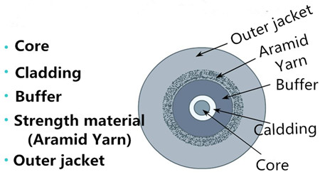
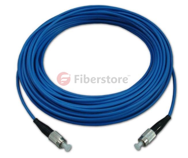
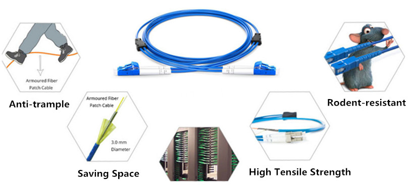
Armored fiber optic cable is one of the most commonly used cables to offer protection for fibers. Generally, armored fiber optic cable contains a helical stainless steel tap over a buffered fiber surrounded by a layer of aramid and stainless steel mesh with an outer jacket. With this unique construction, it can withstand the toughest environments—high temperatures, high pressures, and harsh vibrations as well as animals rodent and moisture. In a word, with the protection of flexible and durable steel tube, armored fiber patch cable will ensure the excellent operation of networks.

ruggedized-fiber-optic-cable-armored-cables

IP67 Waterproof Fiber Optic Cable

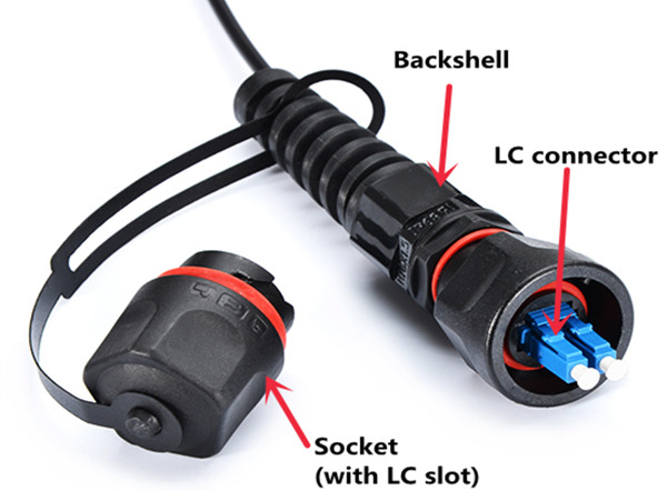
IP67 waterproof fiber optic cable is another kind of ruggedized cables used for outdoor applications. They are with strong PU jacket and stainless steel armor inside for future protection. “IP” in this term is a type of protection rating defined by International Standard IEC 60529. The number “6” and “7” mean this kind of cable possesses a good ability to resist dust and water. According to the connector types, the IP67 waterproof fiber optic cables have several types including IP67 MTP/MPO fiber cables, IP67 LC waterproof fiber cable and so on. IP67 waterproof fiber optic cables will not get damage even stepped, and are anti-rodents and suitable for use in harsh environment like communication towers and CATV (Community Antenna Television), providing protection for your networks. Here is a picture of IP67 LC component details.

ruggedized-fiber optic-cable-ip67-lc-commponent-details

Summary

With the rapid development of optical communication around the world, more and more fiber optic cables are increasingly used in different environments. Under harsh conditions, the ruggedness and durability of common fiber optic cables cannot meet operators’ requirements, especially for exceptional demanding applications. This post mainly introduces three types of ruggedized fiber optic cable. All the cables mentioned above are available in FS.com. If you have any problems about them, please contact us via sales@fs.com.

SMF or MMF, Which to Choose for Date Center Cabling?

It is critically important to choose the suitable cabling plant for data center connectivity, because the wrong decision may leave a data center incapable of supporting future grown, requiring an extremely costly optical cable plant upgrade to move to higher speeds. In the past, multimode fiber (MMF) has been widely deployed in data center for many years because of the high cost of single mode fiber (SMF). However, the price difference between SMF and MMF has been largely negated as technologies have evolved. With cost no longer the dominant decision criterion, operators can make architectural decisions based on performance. So SMF or MMF, which should be chosen for data center cabling? Keep reading and you’ll find the answer.

MMF – Unable to Reach the Distance Need

Many data center operators who deployed MMF OM1/OM2 fiber a few years ago are now realizing that these MMF cannot support higher transmit rates like 40 GbE and 100 GbE. So some MMF users have been forced to add later-generation OM3 and OM4 fiber to support standards-based 40GbE and 100GbE interfaces. But the physical limitations of MMF mean that the distance between connections must decrease when data traffic grows and interconnectivity speeds increase. Deploying more fibers in parallel to support more traffic is the only alternative. So the limitations of MMF have become more serious when it has been widely deployed for generations. The operators must weigh unexpected cabling costs against a network incapable of supporting new devices.

MMF

SMF – A Viable Alternative

Due to the cost of the pluggable optics required, previously organizations were reluctant to implement SMF inside the data center, especially compared to MMF. However, newer silicon technologies and manufacturing innovations are driving down the cost of SMF pluggable optics. Fiber optic transceivers with Fabry-Perot edge emitting lasers (single-mode) are now comparable in price than power dissipation to VCSEL (multimode) transceivers. Moreover, SMF eliminates network bandwidth constraints, where MMF cable plants introduce a capacity-reach tradeoff. This allows operators to take advantage of higher-bit-rate interfaces and wave division multiplexing (WDM) technology to increase by three orders of magnitude the amount of traffic that the fiber plant can support over longer distances. All these factors make SMF a more viable option for high-speed deployment in data center.

SMF

Comparison Between SMF and MMF

With 40 GbE and 100 GbE playing roles in some high-bandwidth applications, 10 GbE has become the predominant interconnectivity interface in large data centers. Put it simply, the necessity for fiber cabling supporting higher bit rates over extended distances is here today. With that in mind, the most significant difference between SMF and MMF is that SMF provides a higher spectral efficiency than MMF. It means that SMF supports more traffic over a single fiber using more channels at higher speeds. This is in stark contrast to MMF, where cabling support for higher bit rates is limited by its large core size. As a matter of fact, in most cases, currently deployed MMF cabling is unable to support higher speeds over the same distance as lower-speed signals.

Summary

The tradeoff between capacity and reach is important as operators consider their cabling options. Network operators need to assess the extend to which they believe their data centers are going to grow. For environments where users, applications, and corresponding workload are all increasing, SMF offers the best future proofing for performance and scalability. And because of fundamental changes in how transceivers are manufactured, those benefits can be attained at prices comparable to SMF’s lower performing alternative.

Fiber Optic Cable Handling Rules

Contaminated fiber optic cables can often lead to degraded network performance or even failure of the whole system. As such, to ensure that fiber optic cables can yield the best possible results of network performance, and it’s of great significance for network engineers to keep in mind how to handle fiber optic cables. Do you have any ideas? This text gives the guide to fiber optic cable handling rues.

Fiber Optic Cable Elements

Before delving into how to handle fiber optic cables, introduction to their makeup elements is required.

fiber optic cable fiver elements

Fiber optic cable generally consists of fiver elements (figure shown above): the optic core, optic cladding, a buffer material, a strength material and the outer jacket. Commonly made from doped silica (glass), the optic core is the light-carrying element at the center of the cable. Surrounding the core is the optic cladding, whose combination with the core makes the principle of total internal reflection possible. Surrounding the cladding is a buffer material used to help shield the core and cladding from damage. A strength material surrounds the buffer, preventing stretch problems when the fiber cable is being pulled. The outer jacket is added to protect against abrasion, solvents, and other contaminants.

The outer jacket on fiber optic patch cord is often color-coded to indicate the fiber types being used. For instance, multi-mode fiber (MMF) is usually in orange to distinguish from the color yellow for single-mode fiber (SMF) through which fiber optic transceivers realize relatively long distance, such as MGBLX1. This Cisco 1000BASE-LX SFP transceiver is able to achieve 10km link length over SMF.

Cisco 1000BASE-LX SFP, SMF

Fiber Optic Cable Handling Rules

Despite its outer protection mentioned above, fiber optic cable is still prone to damage. In such as case, a series of fiber cable handing rules are made to ensure that a cable is handled properly, so as to maintain the optimized performance, minimum insertion loss and safe working environments.

Rule 1: The exposed fiber end from coming in contact with all surfaces should be protected. If you contact the fiber with hard surfaces, then the end of it shall be scratched or chipped, causing the degraded performance.

Rule 2: It’s highly recommenced to lean the connector (plug) end each time it is inserted into an adapter, since since a dirty connector will contaminate an adapter.

Rule 3: If a fiber needs to be pulled, use the connector strain relief. Directly pulling on the fiber may result in the glass breaking.

Rule 4: It’s ill-advised to use your hands to clean a fiber work area. If you use your hands to wipe clean a work area, a piece of glass may get lodged into your hands. Considering the size of the glass, this glass may not be visible to the naked eye, bringing about eye damage.

Rule 5: If possible, always keep a protective cap on unplugged fiber connectors, because covering the adapters and connectors will help to avoid contamination and collection of residue. Besides, store unused protective caps in a resealable container in order to prevent the possibility of the transfer of dust to the fiber. Locate the containers near the connectors for easy access.

dust cap covers for protection

Rule 6: It’s suggestible to use fiber-cleaning materials only once. If optic grade wipes are used to clean the fiber end, they should be discarded immediately after the fiber surface has been wiped to avoid contamination.

Rule 7: The minimum bend radius of the fiber optic cable must be maintained. Surpassing the bend radius may cause the glass to fracture inside the fiber optic cable. Equally, to cause a twist of the cable is also not proposed.

Rule 8: Never look into a fiber while the system lasers are on. Eye damage may occur if you stare directly at a fiber end which is working. Always make sure that the fiber optic cables are disconnected from the laser source, prior to inspection.

After discussion, these handling rules may help you to deal with fiber optic cables and improve your network performance.

Conclusion

Proper handling procedures for fiber optic cables are needed to eliminate the possibility of being contaminated or damaged, and provide a clean environment for the network system. Fiberstore supplies many different types of fiber optic cables with high quality for various applications, like MTP cable. You can visit Fiberstore for more information about fiber optic cables.

10GbE Cables In Network Cabling

There are two basic cable types available for 10GbE applications: copper and fiber-optic cables. As interface speeds increase, expect increased usage of fiber optic cables and connectors for most interfaces. At higher Gigabit speeds (10Gb+), copper cables and interconnects generally have too much amplitude loss except for short distances, such as within a rack or to a nearby rack. This amplitude loss is sometimes called a poor signal-to-noise ratio or simply “too noisy”

Fiber-optic cables

There are two general types of fiber optic cables available: single-mode fiber and multi-mode fiber.

* Single-mode fiber (SMF)—typically with an optical core of approximately 9 μm (microns), has lower modal dispersion than multi-mode fiber and can support distances of at least 10 Km and as high as 80-100 Km (Kilometers) or more, depending on transmission speed, transceivers and the buffer credits allocated in the switches.

* Multi-mode fiber (MMF)—with optical core of either 50 μm or 62.5 μm, supports distances up to 600 meters, depending on transmission speeds and transceivers. Meter-for-meter, single-mode and multi-mode cables are similarly priced. However, some of the other components used in single-mode links are more expensive than their multi-mode equivalents.

Meter-for-meter, single-mode and multi-mode cables are similarly priced. However, some of the other components used in single-mode links are more expensive than their multi-mode equivalents.

When planning data center cabling requirements, be sure to consider that a service life of 15 to 20 years can be expected for fiber optic cabling, so the choices made today need to support legacy, current and emerging data rates. Also note that deploying large amounts of new cable in a data center can be labor- intensive, especially in existing environments.

There are different designations for fiber-optic cables depending on the bandwidth supported.

* Multi-mode: OM1, OM2, OM3, OM4
* Single-mode: OS1

OM3 and OM4 are newer multi-mode cables that are “laser optimized” (LOMMF) and support 10GbE applications. OM3 and OM4 fiber optic cable are also the only multi-mode fibers included in the IEEE 802.3ba 40G/100G Ethernet standard that was ratified in June 2010. The 40G and 100G speeds are currently achieved by bundling multiple channels together in parallel with special multichannel (or multi-lane) connector types. This standard defines an expected operating range of up to 100m for OM3 and up to 150m for OM4 for 40GbE and 100GbE. These are estimates of distance only and supported distances may differ when 40GbE and 100GbE products become available in the coming years. See the Connector Types section below for additional detail.

Newer multi-mode OM2, OM3 and OM4 (50 μm) and singlemode OS1 (9 μm) fiber-optic cables have been introduced that can handle tight corners and turns. These are known as “bend optimized,” “bend insensitive,” or have “enhanced bend performance.” These fiber-optic cables can have a very small turn or bend radius with minimal signal loss or “bending loss.” The term “bend optimized” multi-mode fiber (BOMMF) is sometimes used. OS1 single-mode fiber optics are used for long distances, up to 10,000m (6.2 miles) with the standard transceivers and have been known to work at much longer distances with special transceivers and switching infrastructure. Each of the multi-mode and single-mode fiber optic cable types includes two wavelengths. The higher wavelengths are used for longer-distance connections.

Indoor vs. outdoor cabling

Indoor Cable is  suitable for indoor building applications. Outdoor cables, also known as outside plant or OSP,are suitable for outdoor applications and are water (liquid and frozen) and ultra-violet resistant. Indoor/outdoor cables provide the protections of outdoor cables with a fire-retardant jacket that allows deployment of these cables inside the building entrance beyond the OSP maximum distance, which can reduce the number of transition splices and connections needed.

Fiberstore offers an extensive line of off the shelf bulk fiber optic cable to address your fiber installation needs. We stock 62.5/125, 50/125, and 9/125 bulk fiber optic cable in simplex, duplex (zip cord), breakout, and distribution styles.

The Instructions of Armored Fiber Jumpers

The Classification of Fiber

By transmission method, fiber optic cables mainy are divided into two categories,they are single mode fiber and multimode fiber. Armored fiber optic jumpers in blue is Single Mode Fiber Cable, the transmission distance is long. Armored fiber optic jumpers in blue is Multimode fiber optic calbe,the transmission distance is short.

fiberstore.com

Armored fiber optic jumper connection

All fiber ports are two switches, which are pitch-catch, armored Fiber Optic Cables must be two. When the switch cascade through the fiber port, you must reversed the both ends of armored fiber optic transceivers, when the end of the “receive”, the other end “send”. Similarly, when a termination “send”, the other end “receive”.

The types of armored fiber optic jumpers and fiber port

Armored Fiber Jumper are devided into single mode fiber and multimode fiber. Fiber port switches, fiber optic calbe must be consistent with the used cabling, that is if cabling uses multimode fiber optic cable,the fiber interface switches must perform 1000Base-SX standards, must also use the multi mode armored fiber jumpers; If you are using single mode fiber cabling, then the optical interface switches must perform 1000Base-LX/LH standards, must also use singlemode armored fiber jumpers.

multimode armored fiber

It should be noted that there are two types of multimode fiber, that is,62.5/125μm and 50/125μm. Although fiber optic switch ports are identical, and both are also executive 1000Base-SX standard, but armored core diameter fiber jumpers must be identical to the diameter of the cable core, otherwise, would lead to connectivity problems.

In addition, the type of interconnected fiber ports must be identical, or both multimode fiber ports, or both single-mode fiber port. One end is a multi-mode fiber ports, while the other end is a single-mode fiber ports, it will not be connected together.

Armored Fiber Jumper Precautions

The wavelength of light armored transceiver modules at both ends of the fiber jumpers must be identical , that must be the same at both ends of the fiber wavelength optical module, a simple distinction is the color of the light module to be consistent.Generally, the short optical module uses multimode fiber; long wavelength uses multimode fiber module to ensure the accuracy of data transmission.When using optical fiber, do not bend over and circling, this will increase the light attenuation in the transmission process.After using armored fiber optic jumpers, must use protective sleeve protected fiber optic connector, dust and oil will damage the fiber coupling.

Acronyms
SFP: Small Form Factor Pluggable
SFF: Small Form Factor
XFP: 10 Gigabit Small Form Factor Pluggable
MU: Miniature Unit
LC: Lucent Connector
SC: Subscriber Connector
FC: Fiber Connector
MTRJ: ‘MT’ ferrule, Register Jack latch
ST: Straight Tip

Why Choose the Shielded Cabling System

Shielded VS. Unshielded

In Network Cabling system at all levels, there are two main technical types: Shielded and Unshielded cabling systems. Since the earliest fabric cabling standards since its establishment types on these two technologies are widespread in the market. Germany, Australia, Switzerland and France in the first preference or relatively shielded cabling system, while in other parts of the world, the more popular non-shielded cabling system and will soon be adopted. Both shielded and unshielded gigabit transfer rate to meet the requirements, but when the transmission rate up to Gigabit or even higher, the shield system to support the stability of the advantages of the high frequency transmission becomes very apparent.

What is the function of shielded?
F/UTP

F/UTP cable shielding structure is four pairs of wires in the data cable outside the contractor a layer of aluminum foil shielded, this layer of shielding can be reduced to a great extent the total package:

1. This is the root of the signal transmission cable radiated interference signals on the impact of adjacent data cable (for example: the same bundle of cables in the adjacent data cable).

2. Interference from other data cable or other interference source signal for this cable.

3. For a high quality data transmission system, which is significant in two kinds of effects. If the external interference signal is strong enough it will happen with the normal transmission signal stack a plus, resulting in reduced transmission performance even the entire system can not work properly.

S/FTP

S/FTP structure in addition to the total package of braided foil shield, Twisted Pair Cable is respectively in each pair with a layer of aluminum foil shield to protect the transmission signal does not interfere with each other, so near-end crosstalk attenuation (NEXT)performance dramatically.  NEXT better performance means higher SNR and better transmission quality and faster system output. S/FTP shielded cables NEXT excellent structural performance of other cables (such as non-shielded U/UTP) can not be compared, therefore, ISO11801 on the Cat 7 (600MHz) and Cat 7a  (1000MHz) only provides the S/FTP cable structure, U/UTP cannot meet.

10GBase-T make data cable is facing new problems: Alien Crosstalk

2006 Copper Gigabit Ethernet applications published the proposed new standard transport protocols 10GBASE-T compared to 1000Base-T, its transmission rate increased 10 times. 1000BASE-T copper cabling required parameters (Attenuation, NEXT, Return Loss, etc.) the bandwidth required to reach 1-100MHz, with UTP Cat 5e (Class D) cabling system to meet requirements. 10GBASE-T cabling channel requirements of all component parameters have to be up to 500MHz bandwidth, which requires copper to reach at least Cat.6A (Class Ea) or higher level.

Along with the development of 10GBASE-T, external noise problems become more evident, resulting in a specification for external noise to be used to assess in the same bundle of cables, the interaction between different cables. This is what we call Alien Crosstalk. Alien Crosstalk will increase with the increase of frequency. Worse, 10GBASE-T confronted with external noise, will not be able to “adaptive” to lower the rate at which the network may be subsequently face paralysis. Therefore, to support 10GBASE-T cabling system application, the ability to resist alien crosstalk is vital.

  • Since 10GBASE-T high transmission frequencies and complex coding method is very sensitive to the external noise.
  • Shielding system excellent coupling atttenuation performance makes it naturally have to resist alien crosstalk.
  • The unshielded system against alien crosstalk is usually only on the performance of 0dB.
  • Shielding system in the design is completely satisfy the application of 10G.
The installation of 10GBase-T: U/UTP VS. FTP

Unshielded system: As far as possible away from power cable during installation; Different applications (1Gb/s and 10Gb/s) in the same pipeline transmission will cause the external crosstalk.

Shielding system: With the power cable can be reduced separation distance; Allow different applications (1 Gb / s and 10 Gb / s) in the same pipeline transmission; Does not need additional external crosstalk test field.

The separation distance between the data cable and power cable

In EN50174 standard defines the content of different coupling attenuation value level of data cable, respectively, from A (low coupling attenuation, worse) to D (high coupling attenuation, good) four levels.

Installers need to know which cable separated levels to determine the choice of the data requirements of the standard cable with power cable between the minimum separation distance. Data cable coupling attenuation higher the value and power cables minimum separation distance between the smaller.

Relative to the shielded cable, the unshielded (U/UTP) separation distance between cable and power cable to further. In the implementation of the project, if need the data cable and power cable isolation far distance, we need a bigger size pipe/bridge, or even additional bridge, doing this will no doubt have higher cost, sometimes limited to the bridge installation space. To make matters worse, these additional requirements often neglected or ignored, resulting in network system is the key point of interference.

Grounding

For shielded, unshielded systems and Fiber Optics Cable, all need to implement protective grounding. Because of the need to consider personal and equipment safety, therefore no matter adopt what kind of cabling system, the metal part of the system must be grounded.

For the shielding system, also need to implement the functional ground. Grounded shielding system functions with respect to the implementation of non-shielded systems only difference is that when you install the module connector and the cable shielding mask area area connected.

Overview

Shielding system relative to the unshielded system has been greatly improved EMC performance. For Gigabit Ethernet applications, shielding against external interference effects is essential, and shielded cabling system had to meet the standards in the design of anti-alien crosstalk (A-XT) requirements, can effectively prevent the cable from the adjacent between the external crosstalk.