Brief Introduction to Network Cable Tester

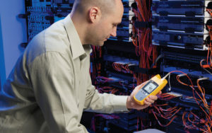
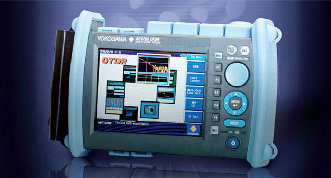
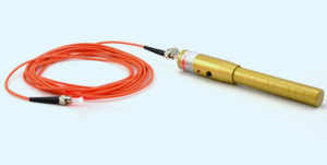
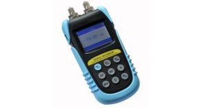
When a fiber optic connection is broken, we all know that fiber optic tester like visual fault locators or OTDR can help to find out where problems may occur and solve the problem. Then, what if a problem occurs in Ethernet networks? It’s time to use a network cable tester. This article is going to give a brief introduction to network cable tester and how to use as well as some abnormal connections that may appear in the testing process.

Basics of Network Cable Tester

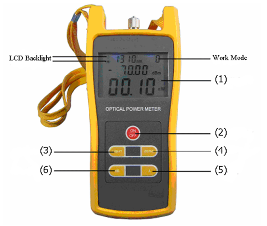
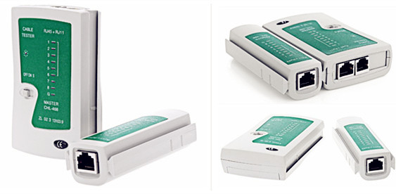
A network cable tester is a device that can identify whether the wires are paired correctly and whether there is a break in the insulation which allows cross-talk between two wires. It even can tell if the cable has the proper level of resistance. Here is a picture of network cable tester shown below. It consists of a main tester (also called master tester) and remote tester. There are night lights on the front panel of them. Besides, most testers have either two or three connectors: RJ-45 for Ethernet, RJ-11 for telephone cable, and BNC for coaxial cable. When testing a Cat5e cable, the two testers are connected by the Cat5e cable. And if the cable works, the lights on both testers will become green sequently from 1 to G. However, if using the tester to test cable with RJ11 connectors, the shining sequence of lights will be different.

network cable tester

Network cable tester can test two common types of cable: coaxial and twisted pair. A basic network cable tester may only test simple connectivity issues but not identify other problems that cause fiber failure. Generally, if a network doesn’t work normally, the problem frequently lies in the user errors or other sides. It rarely is a faulty cable.

Network Cable Tester User Guide

Network cable tester can tell if the Ethernet cable is able to carry a signal when connected to it. Then, how to use a network cable tester to check a cable correctly? Since there are various types of network cable testers in a number of different forms, here is just a simple guide on how to use it.

Notes: never connect a cable tester to a live circuit. Before starting with testing, keep in mind to remove the cable from computer or router.

Step one. Connect the testers. Connect the main tester and remote tester with the cable you want to test. Make sure your cable is plugged in fully and correctly.

Step two. Start the test. When you are ready, turn on the button to send a signal up the cable, which lights up the LEDs on both testers. If something has gone wrong, the red lights will on. Then you need to check your test process or cable carefully.

Step three. Read the test report. The different lights shine and the sequence of lights on shows different problems. Here are some common results you may encounter during the testing process.

network cable tester problems

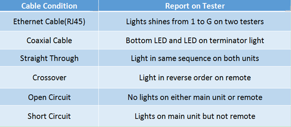
Besides, here are some abnormal connections that can help you to use a network cable tester effectively.

  • If a cable is short circuit, for example No.3, then the two No.3 lights on both testers will not be on.
  • If several cables are not connected, several lights will be off respectively. If less than two cables are connected, none of the lights is on.
  • If two ends of a cable are disordered, the lights on testers will shine in different orders.
  • If three cables are short circuited, none of the corresponding lights is on.
Summary

The network cable tester is designed to calculate how well your high-speed network cables are performing. Poor performance in these cables can result in damage to work, poor Internet access, and general disruption to the network. There are a number of problems which can be sorted out by using the network cable tester, and it will certainly help you to save time trying to find software or hardware solutions.

Optical Power Meter Tutorial

Fiber optic testing in optical communication is an extremely important procedure. Whether installing new cable or testing existing cable, fiber optic testers such as vision fault location, OTDR and optical power meter, are the necessary part that cannot be ignored. This tutorial mainly focuses on the introduction of optical power meter.

Basics of Optical Power Meter

Optical power meter is a common testing instrument. It is often used to accurately measure the power of fiber optic equipment or the power of an optical signal passed through a fiber cable. Sometimes technicians may also use it to measure the power loss of signals. An optical power meter is made up of a calibrated sensor that measures amplifier circuit and a display. The display can show the measured optical power and the corresponding wavelength of the optical signal. The following figure is an example of FSOPM02 handheld optical power meter.

optical-power-meter

Here is a simple function explanation of the optical power meter.
(1) LCD: display the measurement tested, the selected wavelength, the current operation situation and so on
(2) ON/OFF Key: control turning on or off
(3) dB Key: choose the display unit
(4) ZERO Key: press this key for 3s then enter into zero calibration procedure
(5) “λ” Key: choose different wavelengths
(6) LIGHT Key: turn on or off LCD backlight

Steps of Fiber Optic Loss Measurement with Optical Power Meter

Before using an optical power meter, we should do several preparations. First, getting familiar with the function of each button. And it’s better to do some practice tests before going to do testing works. Second, make clear that how and where your fiber cables are installed in case of unnecessary problems. Last but not least, remember to take notes of your testing results. Besides, it’s important to follow safety notes while doing testing with an optical power. After you have done all the preparing works, it’s time to start the testing tasks. Here are the steps.

  • Turn on the optical power meter and press the λ key to choose the wavelength to be tested.
  • Turn on the emitting source and select the tested wavelength, waiting for a while until it becomes stable.
  • Connect the light source (emitting source) to the optical power meter using the fiber cable that is as same as the fiber under test.
  • The optical power meter gets the power measurement value. This value should get close to the tested one.
  • Press the dB key, the reading figure will be shown on the screen. The tested power value will be set to the reference one.
  • Do not cut down the connection between the emitting source and the light source. Then connecting them to the optical fiber link respectively. The reading in dB unit shown on the screen is the tested optical fiber link loss.

Notes: all the connectors and fiber ends should be cleaned with alcohol to ensure an accurate testing result.

Tips for Maintenance

Most fiber optic testers are the instruments providing precise functions for technicians. Therefore they need to be used and maintained properly. Here are some tips for optical power meter maintenance, which should be paid attention to.

  • All the connectors and surfaces should be free from oil, dirt or other contamination to avoid damage and to ensure an accurate result.
  • Dust proof cap should be used to avoid scratch or contamination when optical power meter is not in operation.
  • The light interface is very sensitive, so the connectors should be carefully plugged in and out.
  • If the optical power meter does not need to be used for a long time, it’s better to take out the battery.
Summary

In a word, optical power meter can be used for both optical power measurements and relative loss measurements. Using it properly can help evaluate the quality of fiber optic links transmission. And now on the market, there are different types of optical power meter such as standard type and multifunctional type. Different types have different features. Selecting a suitable one is helpful for a right and reliable cable connection.

Things You Should Know Before Choosing an OTDR

OTDR that is short for optical time domain reflectometry, is a fiber optic tester for the characterization of optical networks that support telecommunications. It can be used to measure loss, optical return loss (ORL) and optical distance on a fiber optic link. Besides, by providing pictorial trace signatures of the fibers under test, an OTDR can offer a graphical representation of the entire fiber optic link. However, there are so many OTDR brands in the market. Choosing the right OTDR for your application can be challenging. So this post is intended for giving some reminders when choosing an OTDR. Hope it may help you.

otdr-application

Why You Need an OTDR?

As we all know, fiber testing is an essential procedure to make sure that the network is optimized to deliver reliable and robust services without fault. So here are two reasons for why an OTDR is needed.

First, service providers and network operators want to insure that their investments into fiber networks are protected. Installers need to use OTDR performing bi-directional tests and providing accurate cable documentation to certify their work. Of course, OTDRs can be used for troubleshooting problems such as break locations due to dig-ups.

Second, premises fiber networks have tight loss budgets and less room for error. Therefore installers have to test the overall loss budget with a light source and power meter, which is a big task. While OTDR can easily pinpoint the causes for excess loss and verify that splices and connections are within appropriate tolerances, which saves lots of time. Besides, it is also the only way to know the exact location of a fault or a break.

What and Where Will You Test?

Before choosing a suitable OTDR, ask yourself the following two questions.

Loss, reflectance, splicing alignment and distance, which one are you going to test? Make sure the OTDR you choose can do what you want easily, quickly and accurately. If you need to make “live” test (like during a “hot cut”—splicing of fibers in a working cable), you need an OTDR that can do an active splice loss measurement in “real time”.

Where are you going to do testing? A good understanding of the applications of an OTDR will help you make the right choice for specific needs. For example, what kind of networks will you test? LAN (local area network), metro or long haul? What is the maximum distance you might have to test? 700 m, 25 km, 150 km?

What Should Be Focused on When Choosing an OTDR?

Many people may be familiar with OTDR but not know how to choose a real right one. Except for the quality that we must focus on, the following three factors also should be attached great importance to.

A Simplified and Task-focused User Interface

Maintaining fiber health is just as challenging and makes fast troubleshooting critical. Almost every OTDR on the market today is designed to cover carrier applications. As a result, many OTDR have very complex user interfaces which require the user to make sense numerous buttons and controls and navigate cumbersome multi-level menus. It’s bad for users improving operating efficiency. So a simplified and task-focused user interface test equipment is important.

simplied-interface

Precision Fiber Channel Information

With the wide use of short patch fibers and various types of fiber connectors, details on network link—loss, connector and reflectance—are critical to ensuring performance. However, OTDR with an attenuation dead zone of more than 3m are no longer applicable for testing data center fiber. But when problems arise, an OTDR with precision fiber channel information can help users with various skill levels efficiently perform troubleshooting and accelerate network recovery.

otdr-wavelengths

Effective Planning and Documentation

As data centers grow and change, it’s challenging to ensure all fibers are installed with certificated quality. Therefore, integrated project management capabilities with cable-by-cable granularity can save time and planning effort. An OTDR with built-in project management capability that allows users plan day-to-day activities without using a personal computer or laptop.

Summary

Selecting a proper OTDR to test your network not only can strengthen its reliability, but also improve the efficiency of the testing job as well as documenting the quality of work. Therefore, before selecting an OTDR, considering the applications and specific needs of your testing work will ensure that it is suited for your applications. FS.COM provides various types of OTDR with different wavelengths such as 850 nm, 1310 nm, 1550 nm and 1625 nm. You can find one that best suits for your network.

Fiber Optic Tester–An Important Tool for Your Network Installation

Fiber optic testing is necessary in optical installations. Accurate testing result can’t be got without high quality fiber optic testers. And there are various kinds of fiber testers available in the market. Today, this article mainly focuses on introducing several common types of fiber optic testers.

fiber-optic-testing

What Should Be tested?

When it comes to fiber optic installation and termination, fiber optic testers cannot be ignored. After the cables are installed and terminated, it’s time for testing. But what should be tested with fiber optic testers? Here are some common parameters which need to be tested.

Power Measurement

Power in a fiber optic system is like voltage in an electrical circuit. It’s important to have moderate power. Because too little power may not distinguish the signal from noise and too much power can cause errors too. So it’s important to measure power.

Loss Testing

Loss testing is the difference value between the power coupled into the cable at the transmitter end and what comes out at the receiver end. In fiber optic system, many things can result in loss such as dirt, connectors and breaks.

Optical Return Loss (ORL)

Optical return loss is the total accumulated light power reflected back to the source from the complete optical span. It includes the back scattering light from the fiber itself and the reflected light from all the joints as well as terminations. Generally, ORL is expressed in decibels (dB). And a high level of ORL will affect the performance of transmission systems.

In addition, some optical testers also can be used for troubleshooting.

Common Types of Fiber Optic Tester

Having known what should be tested in fiber optic testing. Now it’s time to know something about fiber optic testers. Generally, the common types of fiber optic test instruments are visual fault locator (VFL), OTDR (Optical Time Domain Reflectometry), optical power meter, optical multimeter, etc. Following is a brief introduction to the usual types of fiber optic tester.

OTDR

OTDR comprising a laser source and an optical detector operates like radar. It generates short pulses of light and then samples the light scattered back by fiber segments and reflected by connections and other events. OTDR is the main piece of test equipment that is used to analyze a fiber optic link. In addition, as it is possible to calibrate the speed of the pulse as it passes down the fiber, the OTDR also can measure time.

otdr

VFL

VFL is an essential tool for testing cable continuity and locating visual faults. As is known to all, when light encounters a break or sharp bend, it scatters, and scattered light can be observed emerging from the cable. By emitting a laser beam of red light, the VFL can quickly illuminate fiber breaks, damaged connectors, detective splices and tight fiber bends. It even can locate the breaks in a short patch cord, which an OTDR cannot detect. Therefore, VFL is a helpful assistant to the dead zone of DTOR. And it also a basic maintenance tool for fiber network, LAN (Local Area Network) and telecommunication network system.

visual-fault-locater

Optical Power Meter

Optical power meter is a device to measure the power of an optical signal. Its function is to display the incident power on the photodiode. When testing the signal, optical power meter is connected to different places. When testing transmitted power, t is connected directly to the optical transmitter’s output, but it will be connected to the fiber system while testing the received power. In a word, optical power meter is a the primary test instrument for fiber optic networks, as measuring optical signal power is a necessary task for any fiber technician.

optical-power-meter

Optical Multimeter

Optical multimeter, also called optical loss test set, is an instrument that measures several optical parameters such as optical power and wavelength. It adopts an optical laser source and an optical power meter into one handheld instrument, which makes it easy to measure the optical loss of optical fiber links, optical components and fiber networks.

optical-multimeter

Conclusion

In summary, choosing a good quality and high performance fiber optic tester not only can avoid unnecessary problems but also can improve your testing efficiency in fiber optic installation. FS.COM offers a wide range of cable testers and tools to meet any of your demand on copper or fiber installation, termination and troubleshooting. Welcome to visit www.fs.com for more information.

The Applications and Basic Settings of OTDR

OTDR refers to Optical Time-Domain Reflectometer, a test instrument that analyzes the light loss in an optical fiber and verify inline splices on concatenated fiber optic cables and locate faults. If you use fiber optic cables for network connectivity, you ought to know about the applications and basic setting of OTDR.

Applications:
application of OTDR in life

  • OTDR can be used for return loss measurements, although quoted accuracy is not particularly high. It is very useful for measuring points loss on installed systems where it is used to find faults and measure point losses such as caused by splicing. However, to do this accurately is more complicated and time consuming than is commonly supposed. Since a measurement should be taken from both ends of the system and then averaged.
  • OTDR is useful for testing fiber optic cables. It can verify splice loss, measure length and find faults. It simply shows you where the cables are terminated and confirm the quality of the fibers, connections and splices. What’s more, OTDR trace could be also used for troubleshooting, since it can show where breaks are in fiber when trace is compared to installation documentation.
  • OTDR is also widely used for optical cable maintenance and construction. Because it can evaluate the fiber cable length, measure optical transmission and connection attenuation, as well as detect the faulty location of the fiber links.
  • In addition to fiber characterization, OTDR can also be used for sensing chemicals and gases. Because certain substances cause changes to the light guiding properties of the fiber and those can be observed as changes in the measurement curve.

According to the contents above, we could learn that OTDR is a valuable fiber optic tester in many applications. However, if you use it in an improper way, it can be misleading and can lead to some unnecessary mistakes. So it is necessary to understand some basic settings when using OTDR. Using an OTDR is not very difficult, but it does require familiarity. Here are some tips on how to minimize the chance of making a costly mistake.

Basic Settings:

  • Fiber Type – first you should choose singlemode or multimode.
  • Wavelength – you usually start with 850 nm on multimode fiber and 1310 nm on singlemode, since the shorter wavelength has more backscatter so the trace will be less noisy.
  • Measurement Parameters – the typical parameters to be set are distance range, resolution, and pulse width.
  • Event Threshold – it determines how much loss or change will be tagged as an event.
  • Index of Refraction – it is the speed of light in the fiber. You can obtain this figure from the fiber manufacturer. In most cases, you can take it directly from a standard specific sheet.
  • Display Units – they are usually labeled in feet or meters.
  • Storage Memory – this should be cleared so a new figure can be saved or stored.
  • Dead Zone Jumper – you must connect this fiber which should be sufficiently long between the OTDR and the fiber under test. Sometimes you may also have to connect it at the far end of the cable.

OTDR is valuable test instruments that can illuminate problems in your optical fiber. Once you’re acquainted with what it is used for and learn some basic settings about it, you’ll be prepared to detect and eliminate your optical fiber events. It is an ideal test instrument applied to return loss measurement, fiber optic cables testing, optical cable maintenance and construction, as well as sensing chemicals and gases etc.

FiberStore OEM FS2405 Handheld OTDR

Description

FS2405 series of handheld Optical Time Domain Reflector (OTDR) is a high performance, cost-effective optical network analysis tester, with the feature of lightweight, easy to use, high intelligence and having a hotkey for automatic rapid testing. FS2405 Series handhold OTDR is small, powerful and portable. It is battery powered. 3.5 inch TFT-LCD can meet the needs of high luminance environment and night. FS2405OTDR has simple and friendly graphical user interface. Touch screen panel and keyboard button can meet different operator’s habits. Hotkey for rapid testing, and just press the hotkey you can obtain the required operational test results. FS2405 series OTDR provides three power saving modes, Close the LCD screen, equipment sleep and power-off, for users to select according different applications, to ensure that the equipment to achieve a longer working hours.

FiberStore FS2405 OTDR 1310/1550nm, 26/28db

Features

. 1310/1550 dual-wavelength testing
. Visible light source, facilitate to inspect fiber break
. Complete PC analysis software for you to quickly and efficiently generate a professional OTDR reports
. Easy to operate, both the touch-screen panel and keyboard button can completely operate the equipment, meeting different operator’s habits
. All important tests can provide a hotkey to operate automatically, to ensure higher test efficiency 3.5-inch TFT LCD with brightness adjustment support, suit for high luminance environment and night
. With auto-sleep function to save power
. NI-MH battery-powered, low-voltage protection, continuous working time up to 8 hours
. Hardware power switch, thorough stop electrical energy loss, ensures the battery can work longer
. Determine fiber optic cable or fiber optic’s failure point, connection point, breakpoint position
. Describe fiber optic cable or fiber’s loss distribution curve, measure cable, fiber’s length and the loss, attenuation coefficient between two points
. Measure fiber optic cable, optical fiber connector’s insertion loss
. Measure fiber optic cable, optical fiber’s reflection loss

Applications

. Fiber production and research devices
. Fiber Network Testing and Maintenance
. Optical Communication Teaching and Test

Specification

. Source Type: LD
. Connector Type: FC (SC, LC)
. Wavelength: 1310nm 1550nm
. Fiber Type: Single-mode
. Weaken Blind Spot: 15m
. Event Blind Spot: 8m
. Dynamic Range: 26dB
. Maximum Test Distance: 80Km
. Data Storage Capacity: 180 test curve
. Size: 220mm×110mm×70mm

FiberStore is specializing in supplying fiber optic components and network equipment, and we are trying to complete this system. For the OTDR, we provide one year warranty for each domestic and foreign brand product, such as such as JDSU MTS series, EXFO FTB series, YOKOGAWA AQ series and so on. If you would like to know these OTDR price, please contact us or visit our website.

Cable Fault Locator Introduction

When at some local point in a cable, insulation has deteriorated to a degree that a breakdown occurs allowing a surge of current to ground, the cable is referred to as a faulted cable and the position of maximum leakage may be considered a catastrophic insulation failure. After all clearances haven been obtained and the cable has been isolated in preparation for cable fault locating, it is strongly recommended that a fixed plan of attack be followed for locating the fault. As in diagnosing any complex problem, following a set step-by-step procedure will help in arriving at the solution or, in this case, pinpointing the fault efficiently. At the very start, it is a good idea to gather as much information as possible about the cable under test. Information that will help in the fault locating process is:

. Cable type-is is lead covered, concentric neutral (bare or jacketed), tape shield?
. Insulation type- is it XLPE, EPR, Paper?
. Conductor and size – is it CU, AL, standard, solid, 2/0, 350MCM?
. Length of the run – how long is it?
. Splices – are there splices, are the locations known?
. T-taps or wye splices – are there any taps, are the locations known, how long are branches?

Fault location on communication and power cables is a very specialized area of electrical technology. The performance of efficient fault location is very much dependant on good logistics and knowledge. Fast and reliable fault location is dependent on these factors if prelocation of a fault is to be done with high accuracy.

Cable testing, cable diagnosis and partial discharge measurements, will become of higher importance in the future. The condition based preventive maintenance of cable networks, will more and more replace the event oriented maintenance of cable installations.

A good detailed knowledge of the construction of cable networks, cable types and their accessories, simplifies the evaluation of the measured results considerably. Many of these are processes are the essential grounds for correct decisions to be made. The types of cable faults and required steps to do a cable fault location or a diagnosis are one of the most important details that the technician must be aware of.

The purpose of power cables is for the efficient distribution of electrical energy, distribution must be done with a high degree of reliability and safety over a very long period of time. Depending on the application, external environmental and local factors, for example, ground water level, type of ground or voltage levels, different types of cables are used. Cables with impregnated insulation, such as PILC, were installed until be late 60’s and are still being installed in some areas. These cables are today mostly replaced by cables with PVC, EPR, PR or XLPE insulation. Resulting from the changing characteristics of cables their faults and testing have changed considerably.

FiberStore supply a range of cable fault locators, such as Fluke 2042 cable locator, T-C310 cable fault locator, ST620 Cable Fault Locator and so on. As an professional optical communication products manufacturer, we also offer fiber optic tools and other fiber testers, welcome to contact us.

The Common Types of OTDR Test Equipments

OTDR is short for optical time-domain reflectometer, is an optoelectronic instrument used to characterize an optical fiber. It can offer you an overview of the whole system you test and can be used for estimating the fiber length and overall attenuation, including splice and mated-connector losses. It can also be used to locate faults, such as breaks, and to measure optical return loss. There are four types of OTDR, they are Full-feature OTDR, Hand-held OTDR, Fiber Break Locator, and RTU in RFTSs.

Full Feature OTDR

Full-feature OTDRs are traditional. They are feature-rich and usually larger, heavier, and less portable than either the hand-held OTDR or the fiber break locator. despite being characterized as large, their size and weight is only fraction of that of early generation OTDRs. Often a full feature OTDR has a main frame that can be fitted with multi-functioned plug-in units to perform many different fiber measurement tasks. Larger, color displays are common. The full-feature OTDR often has a greater measurement range than the other types of OTDR-like equipment. Often it is used in laboratories and in the field for difficult fiber measurements. Most full-feature OTDRs are powered from an AC source and or battery source.

Handheld OTDR and Fiber break locator

Handheld (formerly mini) OTDRs and fiber break locators are designed to troubleshoot fiber networks in a field-type environment often using battery power. The two types of instruments cover the spectrum of approaches to fiber optic plant taken by the communications providers. Handheld OTDR is more cheaper, more easy to use and light weight than full feature OTDR, sophisticated OTDRs to collect field data and perform rudimentary data analysis upon. They may be less feature rich than full feature OTDRs. Often they can be used in conjunction with PC based software to perform easy data collection with the hand-held OTDR and sophisticated data analysis with the PC-based software. 

The hand-held OTDRs are commonly used to measure fiber links and locate fiber breaks, points of high loss, points of high reflectance, link end-to-end loss, and Optical Return Loss (ORL) for the link. Fiber break locators are intended to be low cost instruments specifically designed to locate the position of a catastrophic fiber event, e.g., point of high reflectance, or high loss. The fiber break locator is an opto-electronic tape measure that is designed to measure only distance to catastrophic fiber events.

In general, hand-held OTDRs and fiber break locators are lighter and smaller, simpler to operate, and more likely to operate using battery power than full-feature OTDRs. The intent is for hand-held OTDRs and fiber break locators to be inexpensive enough for optical technicians to be equipped with one as part of their standard tool kit.

Remote Test Unit (RTU)

An RFTS enables fiber physical plant to be automatically tested from a central location. a central computer is used to control the operation of OTDR-like test components located at key points in the fiber network. These test components will scan the fiber to locate problems. If a problem is found, its location is noted and appropriate Operations Systems (OSs) are notified to begin the repair process. The RFTS can also provide direct access to a corporate database that contains a historical repository for the OTDR fiber traces and any other fiber records for the physical fiber plant.

Since OTDRs and OTDR-like equipment have many uses in the communications industry, their possible operating environment is varied, ranging from indoors to outdoors. Most often, however, these test sets are operated in controlled environments, accessing the fibers at their termination points on fiber distributing frames. Indoor environments include controlled environments such as in central offices (COs), equipment huts, or Controlled Environment Vaults (CEVs). Use in outside environments is rarer, but may include use in a manhole, aerial platform, open trench, or a splicing van.

FiberStore supply all kinds of OTDRs, our OTDRs are available with a variety of fiber types and wavelengths, including single mode fiber, multimode fiber, 1310nm, 1550 nm, 1625 nm, etc.. And we also supply OTDRs of famous brands, such as JDSU MTS series, EXFO FTB series, YOKOGAWA AQ series and so on. OEM portable and handheld OTDRs (manufactured by FiberStore) are also available. What’s more, we also offer many kinds of fiber optic tools. If you would like to know our OTDR price, please send your requirements to sales@fiberstore or visit our website.

A Guide To Optical Power Meter

Definition – What is The Optical Power Meter?

Once you install and terminate fiber optic cables, it’s time to test them. A test should be conducted for each fiber optic cable plant for three main areas: continuity, loss, and power. To do this, you’ll need a fiber optic power meter. An optical power meter (OPM) is a device used to measure the power in an optical signal. The term usually refers to a device for testing average power in fiber optic systems. Other generaly purpose light power measuring devices are usually called radiometers, photometers, laser power meters, fiber optic meters or lux meters.

A typical optical power meter consists of a calibrated sensor, measuring amplifier and display. The sensor primarily consists of a photodiode selected for the appropriate range of wavelengths and power levels. On the display unit, the measured optical power and set wavelength is displayed. Power meters are calibrated using a traceable calibration standard such as a NIST standard.

A traditional optical power meter responds to a broad spectrum of light, however the calibration is wavelength dependent. This is not normally an issue, since the test wavelength is usually known, however it has a couple of drawbacks. Firstly, the user must set the meter to the correct test wavelength, and secondly if there are other spurious wavelengths present, then wrong readings will result.

Before Using a Power Meter

There are a few things you should do to prepare before using a fiber optic power meter. First, read the manual and run some practice tests with your power meter before going onto the job site. Next, prepare documents showing how and where all your cables are installed. Don’t depend on memory because you can easily lose track of your cables, especially if it’s a large project. Also, create a worksheet to document your testing data. Some power meters have a memory feature for keeping your data. These come in handy for large projects as well.

Use Safety Precautions

It’s important to follow safety precautions while testing fiber optic cables with a power meter. Wear eye protection when working with high power cables. Even with low-power layouts, it’s wise to check the connectors with your power meter before looking.

Using a Power Meter for Power Measurement

When measuring fiber optic power with a power meter, attach the meter to the cable. Turn on the source of power (transmitter), and view the meter’s measurement. Compare the meter measurement with the specified correct power for that particular system to be sure it doesn’t have too much or too little power. The reason correct power measurement is so important with fiber optic cables is because the system works similar to electric circuit voltage, and the power must be just the right amount to work properly.

Testing Loss with a Power Meter

A power meter is used to test loss, but a test source is needed as well. The meter will measure the optical power that is lost in every part of the cable. The cable is mated with a working reference cable. Two methods used in loss testing are single-ended loss and double-ended loss. With single-ended loss testing, only the launch cable is used. With double-ended loss testing, a receive cable is also attached to the meter.

There are certain loss guidelines to follow for connectors, splices, multimode fibers, and singlemode fibers. You should understand these guidelines as well as the standard formula for calculating loss before getting started. Other tools that may be required for the processes above include optical loss test kits, matching reference test cables, mating adapters with hybrids, a visual fault locator or fiber tracer, cleaning items, and an ODTR (for outdoor networks). Fiber optic cables can be of great value to companies if they work properly. Use a fiber optic power meter and other useful tools to ensure that your fiber optic system will operate smoothly around the clock.

Three types of equipment can be used to measure optical power loss:

1. Component equipment – Optical power meters and Stabilized Light Sources are packaged separately, but when used together they can provide a measurement of end-to-end optical attenuation over an optical path. Such component equipment can also be used for other measurements.

2. Integrated test set – When an stabilized light source and optical power meter are packaged in one unit, it is called an integrated test set. Traditionally, an integrated test set is usually called an OLTS. Generic Requirements for Hand-Held Stabilized Light Sources, Optical Power Meters, Reflectance Meters, and Optical Loss Test Sets, discusses OLTS equipment in depth.

3. An Optical Time Domain Reflectometer (OTDR) can be used to measure optical link loss if its markers are set at the terminus points for which the fiber loss is desired. The accuracy of such a measurement can be increased if the measurement is made as a bidirectional average of the fiber.

Introduction To Shineway Tech S20A/NA Palm OTDR

Shineway Tech S20A/NA Plam OTDR

Palm optical time domain reflectometer (OTDR) series handheld OTDR supports averaging and real-time tests featuring compact design, excellent stability, user-friendliness and cost-effectiveness. The hotkeys enable convenient events review and analysis. A variety of models are available for singlemode/multimode fibers and LAN/WAN/FTTx applications. With TraceManager software, you can save and transfer test data from OTDR to PC for further analysis, reporting and printing.

FiberStore ShinewayTech S20A/N Palm OTDR 1310/1550nm, 24/24dB

Features

· Comprehensive fiber applications, ideal for LAN/WAN/FTTx certification & trouble-shooting: SM: 1310/1490/1550, 1625/1650nm (Live), up to 45dB; MM: 850/1300nm, 21/24dB
· Fault locating, fiber length/loss measurement, connector/splice/splitter/macrobend/fiber-end detection
· Built-in PON Power Meter for Triple-play live measurement
· Optional Laser Source, SM/MM Power Meter and VFL
· FTTx in-service testing/Testing through ≥1×64 splitter: (1625/1650nm with filter)
· Splitter & fiber-end identifiable
· Auto/Manual(2-point/5-point)/Averaging/Real-time test
· Pass/Fail assessment and ORL test function
· Quick start: <5 seconds
· Perfect user interface, handheld & lightweight (1kg)
· Hotkeys: Easiest operation in the world, push-and-test
· 1000 test records storage
· Bellcore file format (.sor)
· PC software for batch data processing
· RS232/USB data interface
· USB/RS-232 data interface, driver-free
· Multilanguage: EN/DE/IT/FR/ES/PT/RU/KR/CN etc.
· 8 hours continuous operation/20 hours standby
· Dust-shock proof (2m drop test)
· CE, FCC, FDA certificates

Online Optical Signal Detection

When OTDR tests with 1310/1490/1550nm wavelength, the in-service signals transmitting in the tested fiber may not only affect OTDR measurements but also damage the equipments connected to the network (SDH/WDM/PON) and OTDR receiver. Palm OTDR series avoids the problem by starting in-service communication check before testing with message warning and auto termination functions to effectively protect test instruments and communications equipments.

OTDR TraceManager Software

TraceManager software can display, analyze and edit trace files, generate and print comprehensive test and analysis reports in various forms.
· Trace viewing, events analysis
· Multi traces comparison
· Batch editing and flexible printing
· Bidirectional testing

Ordering Information

Standard Package Includes: Instrument, FC/PC connector, NiMH battery, TraceManager software CD, Data cable (USB/RS-232), AC adaptor, Soft carrying case, Warranty card, CE certificate, Certificate of calibration, Quick reference guide.

FiberStore is specializing in supplying fiber optic components and network equipment, and we are trying to complete this system. For the ShinewayTech S20A/N Palm OTDR 1310/1550nm OTDR, we provide one year warranty for it. If you have any problems or special requirement of this OTDR, please feel free to contact us. We will try our best to provide you the best service.