Optical Power Meter Tutorial

Fiber optic testing in optical communication is an extremely important procedure. Whether installing new cable or testing existing cable, fiber optic testers such as vision fault location, OTDR and optical power meter, are the necessary part that cannot be ignored. This tutorial mainly focuses on the introduction of optical power meter.

Basics of Optical Power Meter

Optical power meter is a common testing instrument. It is often used to accurately measure the power of fiber optic equipment or the power of an optical signal passed through a fiber cable. Sometimes technicians may also use it to measure the power loss of signals. An optical power meter is made up of a calibrated sensor that measures amplifier circuit and a display. The display can show the measured optical power and the corresponding wavelength of the optical signal. The following figure is an example of FSOPM02 handheld optical power meter.
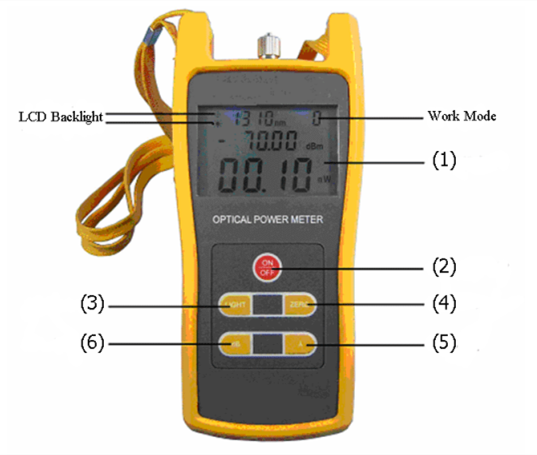
optical-power-meter

Here is a simple function explanation of the optical power meter.
(1) LCD: display the measurement tested, the selected wavelength, the current operation situation and so on
(2) ON/OFF Key: control turning on or off
(3) dB Key: choose the display unit
(4) ZERO Key: press this key for 3s then enter into zero calibration procedure
(5) “λ” Key: choose different wavelengths
(6) LIGHT Key: turn on or off LCD backlight

Steps of Fiber Optic Loss Measurement with Optical Power Meter

Before using an optical power meter, we should do several preparations. First, getting familiar with the function of each button. And it’s better to do some practice tests before going to do testing works. Second, make clear that how and where your fiber cables are installed in case of unnecessary problems. Last but not least, remember to take notes of your testing results. Besides, it’s important to follow safety notes while doing testing with an optical power. After you have done all the preparing works, it’s time to start the testing tasks. Here are the steps.

  • Turn on the optical power meter and press the λ key to choose the wavelength to be tested.
  • Turn on the emitting source and select the tested wavelength, waiting for a while until it becomes stable.
  • Connect the light source (emitting source) to the optical power meter using the fiber cable that is as same as the fiber under test.
  • The optical power meter gets the power measurement value. This value should get close to the tested one.
  • Press the dB key, the reading figure will be shown on the screen. The tested power value will be set to the reference one.
  • Do not cut down the connection between the emitting source and the light source. Then connecting them to the optical fiber link respectively. The reading in dB unit shown on the screen is the tested optical fiber link loss.

Notes: all the connectors and fiber ends should be cleaned with alcohol to ensure an accurate testing result.

Tips for Maintenance

Most fiber optic testers are the instruments providing precise functions for technicians. Therefore they need to be used and maintained properly. Here are some tips for optical power meter maintenance, which should be paid attention to.

  • All the connectors and surfaces should be free from oil, dirt or other contamination to avoid damage and to ensure an accurate result.
  • Dust proof cap should be used to avoid scratch or contamination when optical power meter is not in operation.
  • The light interface is very sensitive, so the connectors should be carefully plugged in and out.
  • If the optical power meter does not need to be used for a long time, it’s better to take out the battery.
Summary

In a word, optical power meter can be used for both optical power measurements and relative loss measurements. Using it properly can help evaluate the quality of fiber optic links transmission. And now on the market, there are different types of optical power meter such as standard type and multifunctional type. Different types have different features. Selecting a suitable one is helpful for a right and reliable cable connection.

Things You Should Know Before Choosing an OTDR

OTDR that is short for optical time domain reflectometry, is a fiber optic tester for the characterization of optical networks that support telecommunications. It can be used to measure loss, optical return loss (ORL) and optical distance on a fiber optic link. Besides, by providing pictorial trace signatures of the fibers under test, an OTDR can offer a graphical representation of the entire fiber optic link. However, there are so many OTDR brands in the market. Choosing the right OTDR for your application can be challenging. So this post is intended for giving some reminders when choosing an OTDR. Hope it may help you.

otdr-application

Why You Need an OTDR?

As we all know, fiber testing is an essential procedure to make sure that the network is optimized to deliver reliable and robust services without fault. So here are two reasons for why an OTDR is needed.

First, service providers and network operators want to insure that their investments into fiber networks are protected. Installers need to use OTDR performing bi-directional tests and providing accurate cable documentation to certify their work. Of course, OTDRs can be used for troubleshooting problems such as break locations due to dig-ups.

Second, premises fiber networks have tight loss budgets and less room for error. Therefore installers have to test the overall loss budget with a light source and power meter, which is a big task. While OTDR can easily pinpoint the causes for excess loss and verify that splices and connections are within appropriate tolerances, which saves lots of time. Besides, it is also the only way to know the exact location of a fault or a break.

What and Where Will You Test?

Before choosing a suitable OTDR, ask yourself the following two questions.

Loss, reflectance, splicing alignment and distance, which one are you going to test? Make sure the OTDR you choose can do what you want easily, quickly and accurately. If you need to make “live” test (like during a “hot cut”—splicing of fibers in a working cable), you need an OTDR that can do an active splice loss measurement in “real time”.

Where are you going to do testing? A good understanding of the applications of an OTDR will help you make the right choice for specific needs. For example, what kind of networks will you test? LAN (local area network), metro or long haul? What is the maximum distance you might have to test? 700 m, 25 km, 150 km?

What Should Be Focused on When Choosing an OTDR?

Many people may be familiar with OTDR but not know how to choose a real right one. Except for the quality that we must focus on, the following three factors also should be attached great importance to.

A Simplified and Task-focused User Interface

Maintaining fiber health is just as challenging and makes fast troubleshooting critical. Almost every OTDR on the market today is designed to cover carrier applications. As a result, many OTDR have very complex user interfaces which require the user to make sense numerous buttons and controls and navigate cumbersome multi-level menus. It’s bad for users improving operating efficiency. So a simplified and task-focused user interface test equipment is important.

simplied-interface

Precision Fiber Channel Information

With the wide use of short patch fibers and various types of fiber connectors, details on network link—loss, connector and reflectance—are critical to ensuring performance. However, OTDR with an attenuation dead zone of more than 3m are no longer applicable for testing data center fiber. But when problems arise, an OTDR with precision fiber channel information can help users with various skill levels efficiently perform troubleshooting and accelerate network recovery.

otdr-wavelengths

Effective Planning and Documentation

As data centers grow and change, it’s challenging to ensure all fibers are installed with certificated quality. Therefore, integrated project management capabilities with cable-by-cable granularity can save time and planning effort. An OTDR with built-in project management capability that allows users plan day-to-day activities without using a personal computer or laptop.

Summary

Selecting a proper OTDR to test your network not only can strengthen its reliability, but also improve the efficiency of the testing job as well as documenting the quality of work. Therefore, before selecting an OTDR, considering the applications and specific needs of your testing work will ensure that it is suited for your applications. FS.COM provides various types of OTDR with different wavelengths such as 850 nm, 1310 nm, 1550 nm and 1625 nm. You can find one that best suits for your network.

Four Questions You May Ask About Fiber Optic Connector Cleaning

Fiber optic connectors, as one of important linking components, can be found everywhere in fiber optic networks. With fiber optic connectors, you can easily add, drop, move and change the networks. And it’s also well known that a clean and reliable optical connector can provide high performance fiber infrastructure and extend the life of network. Then how much do you know about fiber optic connectors cleaning? Today, these questions may help you know more about  it.

Why Fiber Optic Connector Should Be Cleaned?

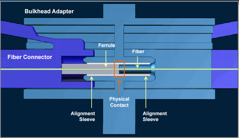
Cleaning consideration is a crucial issue in fiber optic cable technology today. If not cleaned properly, the ferrule in connectors is easy to be damaged when connecting, which can result in high costs. What’s more, it’s known to us that the fiber ferrules in the connectors make physical contact with another within the connectors alignment sleeve. Any contamination or dirt on one of the ferrules can easily be transferred to the mating ferrule, which can cause physical damage to the fiber’s end-face and further lead to information transmission failures. Hence, fiber optic connectors should be cleaned carefully.

fiber-optic-connector

How to Clean Fiber Optic Connectors?

Generally, there are two ways to clean fiber optic connectors. One is dry cleaning, and another is wet cleaning. Following is a brief introduction.

Usually, dry cleaning is to use a reel-based cassette cleaner to wipe the connector end-face against a dry cleaning cloth in one direction. For APC (angled physical contact) polished connectors, it’s essential to ensure the end-face surface mates with the cleaning cloth. Generally, dry cleaning can remove airborne contamination.

As for wet cleaning, first wipe the end-face against the wet area and then onto a dry area to clean potential residue from the end-face. Wet cleaning is more aggressive than dry cleaning, and can remove both airborne contamination and light oil residue.

What Types of Fiber Optic Cleaners Are There?

With more and more fiber optic components widely used, fiber optic cleaning is required for an optimum connection between both active fiber equipment and passive fiber equipment. Without cleaning, your network performance and reliability can be influenced. Here recommends two common types of fiber optic cleaners.

One-Push Cleaner

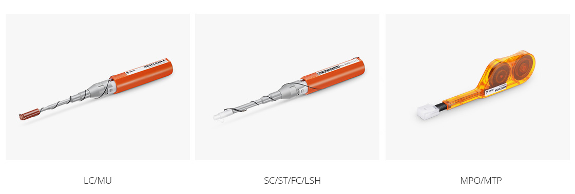
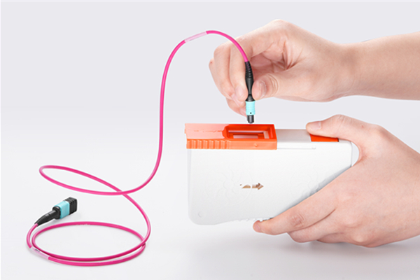
One-push cleaner is designed to clean male connectors, female bulkhead adapters, fiber patch cables and test equipment. It cleans the ferrule end-face by removing dust, oil and other contamination without scratching the end-face. FS provides several kinds of this cleaners such as one-push cleaner for LC/MU 1.25mm ferrules, one-push cleaner for SC/ST/FC/LSH 2.5mm ferrules, one-push cleaner for MTP/MPO connector and so on.

Pen cleaners

Fiber Optic Cassette Cleaner

The cassette cleaner can wipe away contamination from optical connector end-face with ease. It’s very easy to use and suitable for LC/SC/FC/ST/MU/D4/DIN connectors. Usually, the body of this cleaner is made from antistatic materials which will not produce dust. And the common type of cassette cleaner is CLE-BOX fiber optic cassette cleaner.

cassette cleaner

What Should Be Noticed When Cleaning Fiber Optic Connectors?

There are various ways to clean fiber optic connectors. But we still should be careful when cleaning fiber optic connectors because they are easily damaged. Following are some helpful notes that should be given attention to when cleaning connectors.

  • Do not forget to inspect the fiber optic connector, component, or bulkhead before starting cleaning.
  • Do not allow the end of the fiber optic connectors to contact with any surface including fingers.
  • Do not use alcohol or wet cleaning if no residue left on the end-face. It can do harm to the equipment.
  • Do not push it with heavy pressure. Use the fiber optic cleaner correctly by inserting it at the correct angle and clean connectors carefully.
  • Do not forget to reinspect the connectors when cleaning has been finished.
Conclusion

Keeping fiber optic end-face clean is extremely important and one of the most critical requirements for ensuring accurate measurements and operation. Hence, choosing suitable cleaning tools for fiber optic connectors is significant. FS provides a number of fiber optic cleaning tools such as pen cleaner, cassette cleaner and so on. All this cleaning tools have good quality and high performance, which can make your fiber optic cleaning works easier and more convenient. Welcome to contact sales@fs.com.

Introduction to Fiber Optic Cleaving

Optical fiber has brought changes to the telecommunication industry throughout the world, therefore, it is essential for us to learn some skills necessary for working with optical fiber. It is known to all that when adopting or splicing a fiber, clean ends should be assured. And fiber optic cleaving serves as one of the basic and important steps to ensure fiber ends clean and smooth, thus the significance of cleaving process cannot be underestimated. This article aims at providing some basic knowledge about cleaving and introducing common tools for cleaving.

Basics of Fiber Optic Cleaving

Fiber optic cleaving is one of the several processes in the preparation for a fiber splice operation. The purpose of cleaving is to prepare the end of the fiber so that it makes a very nearly perfect right angle with the body of the fiber and that this end face is nearly perfectly smooth. With a well-performed cleaving operation, a clean and flat endface was created perpendicular to the length of the fiber, with no protruding glass on either end. Besides it can also help to achieve a successful low loss splice of an optical fiber.

The technique of Fiber Optic Cleaving

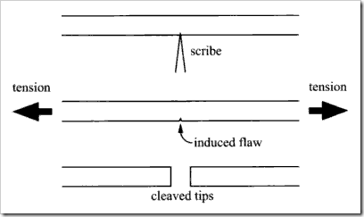
A general strategy involved in the technique of fiber optic cleaving is known as the scribe-and-tension or scribe-and-break strategy. With the use of cutting tool made from materials such as diamond, sapphire or tungsten carbide, this process involves the introduction of a crack in the fiber, then followed by the application of tensile stress in the vicinity of the crack.

Cleaving technique

However, the specific implementations of the cleaving can be various thus lead to cleaves of different qualities. Some implementations may apply the tensile force uniformly across the cross section of the fiber while others might bend the fiber around a curved surface, causing excessive tensile stress on the outside of the bend. Besides, the crack in the fiber may also be generated in different ways: the crack may be introduced at a single point on the circumference or it may be generated all along the circumference of the fiber prior to the application of the tensile force. The circumferential introduction of the crack often allows fibers of considerably large diameters to be cleaved while maintaining high quality of the cleave.

Common Cleaving Tools

Basically, there are two kinds of cleaving tools which are commonly employed in fiber optic cleaving: pen-shaped scribe and mechanical cleaver.

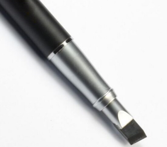
Pen-shaped scribe looks like a ballpoint pen, but with a small wedge tip made of diamond or other hard material that is used to scratch the fiber manually. After scratching the fiber, the operator pulls the fiber to break it. In essence, both the scribing and breaking process are under manual control, making it more dependent on operator technique and less predictable as they require operators to exert force manually for breaking the fiber. So, an experienced operator is required to produce good cleaves.

Fiber optic scribe

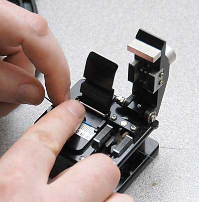
And the other tool is mechanical cleaver, which is widely used because it can produce nicer and more repeatable cleaves. This cleaver is much easier to use thus the specific training is not essential. Just clamp the fiber in the correct position into the cleaver. Then, a force is applied and the fiber gives a nice break at the scribe.

Mechanical cleaver

Conclusion

Since fiber splicing requires mating two fiber ends together, any defect of the ends would impact the performance of fiber splicing. So in order to achieve good fiber optic splices or terminations, it is extremely important to cleave the fiber properly. And a good cleaver can help better finish the whole cleaving process.

A Brief introduction of MTP One-Push Cleaner

As fiber optics is now widely used in telecommunication and networking, more attention should be paid to the cleanliness of the interfaces since it can directly influence the quality of transmission. The newly published MTP one-push cleaner is designed to solve this problem thus to make it ever easier to clean the MPO/MTP connectors.

The Introduction of MTP One-Push Cleaner

This one-push cleaner is a high-performance and user friendly device aimed to clean the ferrule end-faces of MPO&MTP connectors. And it can be implemented to clean both connectors and adapters with the innovative one-push action. Unlike the traditional cleaning methods, it uses the latest cleaning technologies and free from any alcohol or other harsh chemicals. Moreover, it is supposed to clean all 12 fibers at once, meanwhile, to clean both exposed jumper ends and connectors in adapters, which are proved to be cost effective and time saving.

The Importance to Use MTP One-Push Cleaner

It is claimed that more than 85% of the fiber optic network failures in optical communication facilities is resulted from contaminated optical connector end face. However, to clean the connectors regularly may help prevent things like performance degradation, network failure and transmission error from happening. So, in order to enable connectors to operate in the best condition, it is essential to make sure that all optical fibers are clean and free of dust and dirt. And the maintenance of fiber optic systems attaches great importance to the cleaning of fiber optic facilities.

The Features of MTP One-Push Cleaner

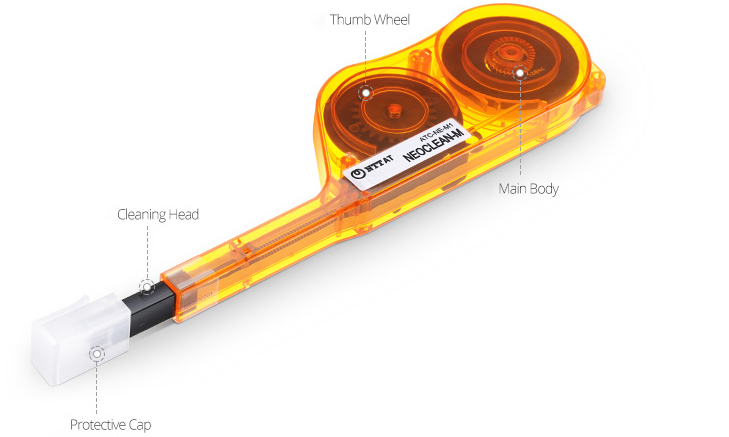
The NEOCLEAN-M MTP/MPO one-push cleaner, a newly published product that is specific to the cleaning of MPO/MTP connectors. It is designed to achieve efficient and quick cleanliness of the connector end faces by removing dust, oil and other debris alike. Without nicking or scratching the end face, it serves as an ideal instrument for all MPO/MTP connectors. The one-push cleaner obtains several features:

  • Easy one-hand operation
  • 600+cleanings per unit
  • Clean ferrules with or without guide pins
  • Narrow design reaches tightly spaced MPO adapters
  • Intermateability with FOCIS-5 (MPO)

The Application of MTP One-Push Cleaner

The one-push cleaner can be commonly used in various working environments,such as:

  • Fiber network patch panels
  • Cable assembly manufacturing
  • Suitable for field or laboratory use
  • Outside Plant and Fiber To The Home
  • Data Centers

As one of the most popular fiber cleaner which is generally accepted in the field of networking, the one-push cleaner offers much convenience and flexibility for users with outstanding performance. In the following, I would like to illustrate how to use this one-push cleaner efficiently.

The picture below shows the whole details of an one-push cleaner, a guide cup is placed on the cleaning tip of the cleaner, and on the top of which exists a cover used for protection.

MTP One-Push Cleaner

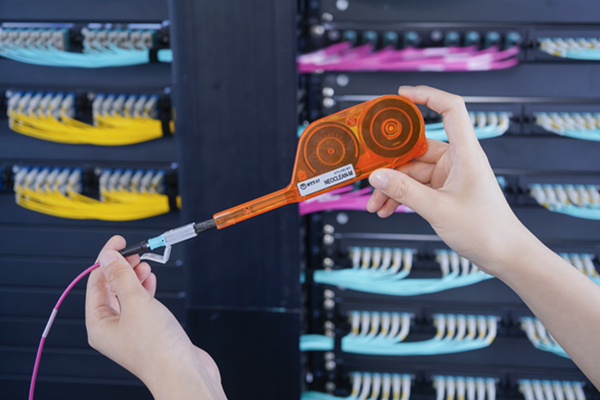
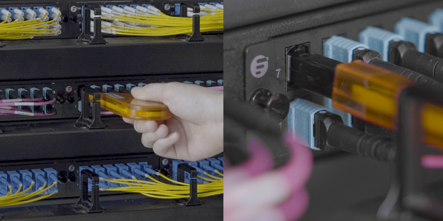
If you want to clean a connector, insert the cleaning tip into the connector with the guide cup as the following picture, then press the cleaner until you hear a click. The whole process of cleaning is then finished.

MTP MPO cleaner

If you want to clean an adapter, firstly remove the entire protective cap, then insert the cleaning tip into the adapter. Pressing the cleaner, after you hear a click, a cleaning for a fiber optic adapter is done. It is especially useful during the test since the equipment for testing usually have an interface of the adapter.

MTP MPO adapter cleaning

This NEOCLEAN-M MTP/MPO one-push cleaner mentioned above only account a very small part of the cleaning products offered by FS. For more detailed information and other fiber optic cleaning choices, please visit www.fs.com.

A Guide to Fiber Optic Splicing

Fiber Optic Splicing Basis

It is vital for any company or fiber optic technician involved in telecommunications to grasp knowledge of fiber optic splicing methods. Fiber optic splicing refers to joining two fiber optic cables together. It can result in lower light loss and back reflection. Two methods of fiber optic splicing are available: fusion splicing and mechanical splicing. Which technique best fits your economic and performance objectives? Keep reading the following statement and find the answer.

Fusion Splicing vs. Mechanical Splicing

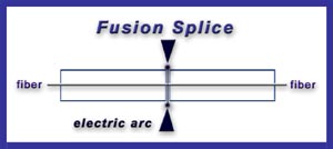
Fusion splicing is an optical junction of two optical fibers by permanently welding them together with heat generated by an electronic arc (called arc fusion). It is the most widely used method of splicing because it provides least reflectance and lowest loss, as well as providing the strongest and most reliable joint between two fibers.

fusion splicing

Fusion splicing steps:

  1. Prepare the fiber: strip the protective coatings, jackets, tubes, strength members, and leave only the bare fiber showing. Pay attention to cleanliness.
  2. Cleave the fiber: using a good fiber optic cleaver here is essential to a successful fusion splice. The cleaved end must be mirror-smooth and perpendicular to the fiber axis to obtain a proper splice.
  3. Fuse the fiber: alignment and heating are the two steps within this step. Alignment can be automatic or manual depending upon the equipment you have. Once the fusion splicer unit are properly aligned, then you can use an electrical arc to melt the fibers and permanently weld the two fiber ends together.
  4. Protect the fiber: protecting the fiber from bending and tensile forces will ensure the splice not break during normal handling. Using heat shrink tubing, silicone gel and/or mechanical crimp protectors will keep the splice protected from outside elements and breakage.

Aligning and holding in place by a self-contained assembly, a mechanical splice is a junction of two or more optical fibers. Not permanently joined, the fibers are just precisely held together so that light can pass from one to another.

mechanical splicing

Mechanical splicing steps:

  1. Prepare the fiber: same with the step of fusion splicing.
  2. Cleave the fiber: the process is identical to the cleaving for fusion splicing.
  3. Mechanically join the fibers: simply position the fiber ends together inside the mechanical splice unit. The index matching gel inside the mechanical splice apparatus will help couple the light from one fiber end to the other.
  4. Protect the fiber: the completed mechanical splice will provide its own protection for the splice.
Tips for Better Splicing
  1. Clean your splicing tools thoroughly and frequently.
  2. Operate and maintain your cleaver properly.
  3. For fusion splicing, the fusion parameters must be adjusted minimally and methodically.
Which Method Is Better?

Cost and performance are the two deciding factors for choosing one method over the other. Mechanical splicing has a low initial investment ($1,000 – $2,000) but costs more per splice ($12-$40 each). Fusion splicing has lower cost per splice ($0.50 – $1.50 each) but higher initial investment ($15,000 – $50,000). As for the performance, fusion splicing produces lower loss and less back reflection than mechanical splicing. Fusion splices are primarily used with single-mode fiber, while mechanical splices work with both single-mode and multimode fiber.

Conclusion

To sum up, the two fiber optic splicing methods have its own advantages. Fusion splicing is invested for long haul single-mode networks, while mechanical splicing is used for shorter local cable runs. For better fiber optic splicing, besides the above splicing steps, high-quality fiber optic splicing tools are also essential, such as fusion splicers, fiber optic cleavers, etc. After all, good methods and excellent tools will produce the best performance.

Why Is Fiber Cleaning Necessary?

At a BICSI Conference in 2008, JDSU stated, “Contamination is the number-one reason for troubleshooting optical networks.” For the long-term reliability of any network, fiber cleaning is critical and it is at the heart of the profitability of successful fiber deployment. This paper will introduce the necessity of fiber cleaning and then give two tips on fiber protection against dust contamination.

Four reasons for fiber cleaning are listed below:

Signal Failure

As you know, fiber optic networks work by carrying pulses of light between transmitters and receivers. Contamination and dirt will block the signal and lead to light loss, reducing power and efficiency. The amount of light loss shrinks correspondingly as links carry higher data rates, which makes cleaning even more essential. Dirty equipment can give rise to network failure or paralysis.

Equipment Failure

Dirt can cause permanent damage to the end-face, digging into the surface and creating pits that increase back reflection. Failures in the network caused by dirt can increase costs and install time because damaged equipment may need to be tracked down and replaced, which means more time on-site and greater expenditure. Both of the two will impact the overall budget for a deployment.

Angry Occupants

It is naturally going to enrage consumers and building owners by leaving a mess in a subscriber’s home or the common areas of an apartment building. They’d like to have the benefits of fiber broadband rather than the dirt or damage to their property when it is installed.

Adopting Proper Cleanliness Procedures

While it is easy to focus on more visible debris, dirt is most dangerous at a microscopic level, particularly when it comes to the end-faces of connectors. For example, simply touching the ferrules of a connector will deposit significant amounts of body oil onto the end face. Best practice for this issue is to use high-grade, completely lint-free wipes (aiming for clean room quality) and pure Isopropyl Alcohol (IPA).

On top of this, here are two areas to keep an especially close eye on:

Mating and Unmating

The actual process of mating and unmating connectors can also cause damage to the ceramic. Therefore, aim to minimize this plugging and unplugging as much as possible and ensure you inspect the two end-faces for dirt or debris that could be crushed between them. This can cause permanent damage, such as scratches, cracks or pits that will require re-termination, not just cleaning. Moreover, make sure you inspect any other equipment ports that the connector is being plugged into, as they can also harbour contamination.

Don’t Rely on Dust Caps

Many people may think that if you don’t take the dust cap off your factory terminated connector until you plug it in, it’ll keep dirt free. After all, it was packaged in a sterile factory environment. In fact, dust caps are preventing damage to the end-face, rather than stopping all contamination reaching the connector.

FS Fiber Cleaning Solution

As a professional supplier in the optical industry, FS has various high-quality and low-price fiber optic cleaning tools, such as fiber connector cleaner, optical connector cleaning cards, one push fiber optic cleaner for 1.25mm connectors, etc. These tools can help to ease or remove all kinds of dirty particles, such as dust, dripping and moist. Choosing any kind of fiber optic cleaning tools in FS will give you a surprise!

The Applications and Basic Settings of OTDR

OTDR refers to Optical Time-Domain Reflectometer, a test instrument that analyzes the light loss in an optical fiber and verify inline splices on concatenated fiber optic cables and locate faults. If you use fiber optic cables for network connectivity, you ought to know about the applications and basic setting of OTDR.

Applications:
application of OTDR in life

  • OTDR can be used for return loss measurements, although quoted accuracy is not particularly high. It is very useful for measuring points loss on installed systems where it is used to find faults and measure point losses such as caused by splicing. However, to do this accurately is more complicated and time consuming than is commonly supposed. Since a measurement should be taken from both ends of the system and then averaged.
  • OTDR is useful for testing fiber optic cables. It can verify splice loss, measure length and find faults. It simply shows you where the cables are terminated and confirm the quality of the fibers, connections and splices. What’s more, OTDR trace could be also used for troubleshooting, since it can show where breaks are in fiber when trace is compared to installation documentation.
  • OTDR is also widely used for optical cable maintenance and construction. Because it can evaluate the fiber cable length, measure optical transmission and connection attenuation, as well as detect the faulty location of the fiber links.
  • In addition to fiber characterization, OTDR can also be used for sensing chemicals and gases. Because certain substances cause changes to the light guiding properties of the fiber and those can be observed as changes in the measurement curve.

According to the contents above, we could learn that OTDR is a valuable fiber optic tester in many applications. However, if you use it in an improper way, it can be misleading and can lead to some unnecessary mistakes. So it is necessary to understand some basic settings when using OTDR. Using an OTDR is not very difficult, but it does require familiarity. Here are some tips on how to minimize the chance of making a costly mistake.

Basic Settings:

  • Fiber Type – first you should choose singlemode or multimode.
  • Wavelength – you usually start with 850 nm on multimode fiber and 1310 nm on singlemode, since the shorter wavelength has more backscatter so the trace will be less noisy.
  • Measurement Parameters – the typical parameters to be set are distance range, resolution, and pulse width.
  • Event Threshold – it determines how much loss or change will be tagged as an event.
  • Index of Refraction – it is the speed of light in the fiber. You can obtain this figure from the fiber manufacturer. In most cases, you can take it directly from a standard specific sheet.
  • Display Units – they are usually labeled in feet or meters.
  • Storage Memory – this should be cleared so a new figure can be saved or stored.
  • Dead Zone Jumper – you must connect this fiber which should be sufficiently long between the OTDR and the fiber under test. Sometimes you may also have to connect it at the far end of the cable.

OTDR is valuable test instruments that can illuminate problems in your optical fiber. Once you’re acquainted with what it is used for and learn some basic settings about it, you’ll be prepared to detect and eliminate your optical fiber events. It is an ideal test instrument applied to return loss measurement, fiber optic cables testing, optical cable maintenance and construction, as well as sensing chemicals and gases etc.

Introduce Two kinds of Fiber Optic Termination Tools

What is termination? according to the Wikippedia, you can find nearly 20 different uses and meanings of this word. But here in the fiber termination tools which used in fiber cabling, the termination is the preparation of the end of a fiber so that it may be connected to another fiber or device. Fiber optic termination kit is used for fiber termination and contains tools those used to strip, prep, terminate, crimp, polish and inspect fiber optic cable connectors.

Fiber Connector Termination Tool Kit FB-3601

FiberStore Fiber Connector Termination Tool Kit FB-3601

This tools kit included: Fiber Optic Stripper CFS-2, Kevlar Scissor KC-1, Carbide Scribe Tool, Tri-Hole Fiber Optic Stripper, Fiber Jacket Stripper, Universal Connector Crimp Tool, Buffer Tube Stripper, Round Cable Jacket Stripper,400x Universal Fiber Microscope, LC adapter for 400x Microscope, Flexible Piano Wire, Precision tweezers, 24 Part Connector Hot Oven, Thermometer, EPO-TEK 353ND Epoxy 4g/Pkg, Epoxy Application Syringe 3ml, 15µm Polish Film, 5µm Polish Film, 1µm Polish Film, 0.02µm Polish Film, 2.5mm Universal Polish Puck(SC/ST/FC), LC polish puck, 5.9 Rubber Polish Pad, Glass Polish Plate, Safety Glasses, IPA Fiber Cleaning Wipes(Pre-Moistened), KimWipes 280piece/box, NTT fiber optic connector cleaner, Alcohol Dispensing Bottle with Locked 100ml,Water bottle, 3M Electrician Tape, Utility Knife, Cleaning Swabs, Utility Component Box, Black Marker, Carrying Case (430×330×135mm).

Fiber Optic Termination HT-K3032

FiberStore Tool Kit for Fiber Optic Termination HT-K3032

The HT-K3032 it included: Carbide Scribe, Syringe, Stripper, A/B Fast Epoxy Glue, Cleanser, ST Polish Disc, SC Polish Disc, Wipe Paper, Kevlar Cutter, Glass Working Pad, Ratcheting Crimp Tool
with Die, 6µm Diamond Polish Film, 1µm Diamond Polish Film, 05µm Aluminum Oxide Polish Film, Rubber Working Pad.

A fiber termination tool can be used for varying purposes, and it can be used in the following process:

The first, using a chemical solvents or mechanical strippers to strip the buffer and coating material from fiber before being cleaned with alcohol;

The second, we have to using a metal or diamond blade to nick the fiber before the tension which applied causing it to break;

The third procedure is using grit abrasive paper to polish the fiber until the fiber end is smooth;

The four procedure comes to using a microscope (be better with high power pixel, so you can see it clearly) to inspect the end of fiber which to insure that the end of fiber is really smooth;

Then let’s come to last step, we have to attach the connectors to the fibers or splicing them to make them joined together.

Fiber Optic Tool Kit is very important in fiber optic installation and maintenance works. It puts a certain type of fiber optic tools into one kit to make work easier. The tools used in the kit are thoughtfully assembled and stored in high-quality cases which keep them safe, neat and in proper working order. If you would like to know the fiber optic tool kit price, and want to know more fiber optic cable lineman tools, please visit our website.

Sumitomo FC-6S Precision Fiber Cleaver

Before introduce Sumitomo FC-6S fiber cleaver, let’s talk about what is optical fiber cleaving? Simply put, optical fiber cleaving is the art of cutting glass optical fibers at a perfect 90°angle with a mirror like surface. This isn’t as easy as it sounds. As we know the quality of the bare fiber end face will determine the quality of the joint of the fibers in the fiber optic fusion process, and the joint point quality means higher or lower attenuation of the fiber connection line. So the fiber cleaver is very important in the fiber splicing process, it works together with the fusion splicer to meet the end needs.

Why do we need to cut the fiber at a perfect 90°angle at all? Well, this is required when we want to fuse two optical fibers together. Optical fiber fusion splicing always requires that the fiber tips have a smooth end face that is perpendicular to the fiber axis. The cleave quality is very important in determining the fusion splicing loss. This is especially true for specialty fibers such as erbium-doped fibers and dispersion compensating fibers.

The basic idea of optical fiber cleaving is first to scratch the fiber with a very hard diamond edge scribing tool, which induces a sufficiently large surface crack, then the fiber cleaver applies a tensile stress to the fiber which causes the crack to expand rapidly across the fiber cross section. Some other fiber cleavers apply the tensile stress first and then scratch the fiber with the diamond edge scribing tool.

Sumitomo FC-6S Introduction

FiberStore

With the introduction of FC-6 series, Sumitomo now has the utimate tool for single and ribbon cleaving. Built on a robust high quality platform, the FC-6 is ideal for use with fusion splicing or other precision applications, setting a new standard for flexibility and performance.
The FC-6 is available with a single fiber adapter for 250 to 900 micron coated single fibers. It is a simple operation for the user to remove or install the single fiber adapter and alternate between mass and single fiber cleaving.

An optional fiber scrap collector can be installed to help maintain loose scraps resulting from cleaving. The scrap collector works to automatically grab and store the scrap fibers as the cleaver’s lid is raised following a completed cleave.

Sumitomo FC-6S Main Features

. Used for single fiber cleaving
. Utilizes an Automatic Anvil Drop for Fewer Required Steps and Better Cleave Consistency
. Prevents Double Scoring of the Fibers.
. Has Superior Blade Height and Rotational Adjustment.
. Available With Automatic Fiber Scrap Collection.
. Can Be Operated With Minimal Steps

FiberStore supply all kinds of high precision fiber cleavers and fiber testers . Welcome to contact us if you need this Sumitomo FC-6S fiber cleaver at a large quantity or have some questions, we will do our best to provide you the best service.