Things to Know About Bend Insensitive Multimode Fiber

Bend insensitive multimode fiber (BIMMF) has become a very active area within the telecommunication industry once it was introduced and popularized. It typically signifies technical advancements in the production of multimode optical fiber for easier installation, and cable management for multimode fiber cables through improvements in bend insensitivity. This article will focus on some useful information about BIMMF from the perspective of its working principle, performance in networking and unique advantages as well.

What Is Bend Insensitivity?

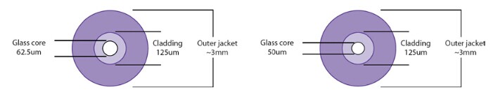
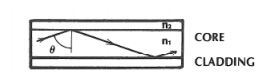
An optical fiber consists of a core and a cladding. Although both of these regions are made from glass in telecommunications grade fibers, they are significantly different from each other. Each region is designed to capture light within the core and transmit it to the opposite end of the fiber. During this process, the light may follow many paths, depending on the angle at which the light hits the boundary, it is either reflected back into the core, or it gets lost into the cladding. Therefore, the light losses during transmission cause a weaker optical signal at the other end.

light traveling in fiber

Optical fiber is sensitive to stress, particularly bending. When conventional fibers are bent tightly, some of the signal will leak out of the fiber at the site of the bend due to macrobend loss, which will results in system failure and unplanned downtime. Various attributes in the fiber determine when this occurs. The relative ease with which this happens is known as bend sensitivity. On the contrary, bend insensitivity is a positive feature that can provide for additional robustness and simplify installation of multimode fiber.

Introduction to Bend Insensitive Multimode Fiber (BIMMF)

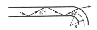
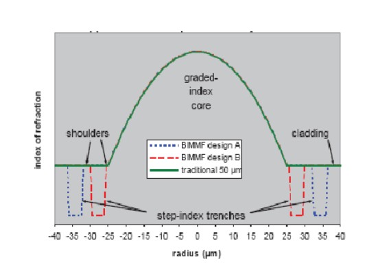
Bend-insensitive multimode fiber (BIMMF) has an innovative core design that enables it to significantly reduce macrobend loss even in the most challenging bend scenarios. It is hence natural that bend insensitive multimode fiber can withstand tough treatment. The difference between traditional multimode fiber and BIMMF mainly lies in the fact that the BIMMF design can include an optical trench. This trench effectively improves the fiber’s macrobend performance by retaining more of the light that would have escaped the core of a traditional multimode fiber. So when compared with standard multimode fibers, BIMMF is proved to be a good candidate for loss and bend critical applications because of their higher immunity to bending losses, without loosing performances or compatibility to other standard high bandwidth multimode fibers.

Compatibility With Conventional Fibers

There is a lot of buzz around the issue of bend insensitive fiber— is it compatible with regular fibers? Can they be spliced or connected to other conventional fibers without problems? Modeling and testing on BIMMF has shown that an optimized BIMMF is backward compatible and can be mixed with non-BIMMF without inducing excess loss. Hence, BIMMF and MMF could easily be mixed in an optical channel without complicating the estimation of losses. Moreover, BIMMF may lead to higher tolerance to possible misalignments when two connectors are mated. This is an additional positive feature for 40 and 100 Gigabit applications.

In summary, a well-designed BIMMF complies with all relevant industry standards and adheres to the following:

  • BIMMF OM2, OM3 and OM4 multimode fibers are fully compliant and fully backward-compatible with all relevant industry standards.
  • BIMMF is fully backward-compatible and may be used with the existing installed base of 50/125um multimode grades including OM2, OM3 and OM4.
  • BIMMF may be spliced or connectorized to conventional 50/125um fiber types with commercially available equipment and established practices and methods, no special tools or procedures are required.
  • BIMMF not only meets all relevant macrobend standards, but sets a new level of bend performance.
Advantages of BIMMF

Bend insensitive multimode fiber is available in all laser optimized grades, OM2, OM3 and OM4, and exhibits 10 times less signal loss in tight bend scenarios and therefore protects enterprise and data center systems from unplanned downtime due to signal loss and associated significant revenue loss.

This fiber type offers extremely low bending loss at both the 850 and 1300 nm operating windows, while maintaining excellent long term fiber strength and reliability. The fiber can be installed in loops as small as 7.5 mm radius with less than 0.2 dB bending loss at 850 nm and 0.5 dB at 1300 nm.

Maximum induced bend loss performance at 850 nm Standard for multimode fibers IEC 60793-2-10 Bend Insensitive MMF (no standard currently)
Bend radius 37.5 mm 7.5 mm
Number of turns 100 2
Conventional MMF 0.5 dB
Bend Insensitive MMF 0.05 dB 0.2 dB

In addition, bend insensitive multimode fibers enable new possibilities for cable and patch panel design to further improve the benefits of using fiber. Optical cable manufacturers can now design thinner, more flexible trunk cables, making for easier cable installation and further improving airflow in conduits, patch panels and racks. Due to the ability of the fib cable to be bent tightly with significantly less signal loss, connector modules can be made smaller which in turn leads to an increased density within racks and smaller racks.

Conclusion

Bend insensitive multimode fiber has been widely employed to enhance fiber management in data centers, high performance computing and enterprise LANs. Since it is a real advance to current standard multimode fibers, BIMMF is recommended for bend and loss critical applications. What should be noticed is that BIMMF also should be handled with appropriate care as all optical glass fibers.

Establishing 40G Links With OM3 and OM4

To meet the needs of Internet users, the business users in particular, who require faster speeds, greater scalability, and higher levels of network performance and reliability, data centers have experienced infrastructure transformation, from 10 Gbps to 40 Gbps and then to 100 Gbps, or even higher, never-ceasing. Actually, during this bandwidth migration, 40G provides an efficient use of hardware and a more logical upgrade path to 100G. And in establishing 40G links, fiber optic cabling, (eg OM3 and OM4) has become an integral part of the overall system design.

Background Information

The Institute of Electrical and Electronics Engineers (IEEE) 802.3ba 40/100G Ethernet Standard was ratified in June 2010 to support the fast-growing demands for bandwidth in data centers. The standard provides specific guidance for 40G/100G transmission with multi-mode fibers (MMFs) and single-mode fibers (SMFs). OM3 and OM4 are the only approved multi-mode fibers included in this standard.

Using OM3 and OM4 for 40G Links

The IEEE 802.3ba only specified OM3 for a maximum reach of 100 m in its original draft. Later, efforts have been made to win the approval to include OM4 in the standard. As a matter of fact, OM4 can achieve the greater reach of 150 m compared with OM3. In 40 GbE transmission which uses MMFs, an optic module interface is used for the simultaneous data transmission and data reception. Like JNP-QSFP-40G-LX4, this Juniper Networks proprietary 40G-LX4 transceiver listed on FS.COM realizes 100 m transmission on OM3, and 150 m transmission on OM4. Besides, JNP-QSFP-40G-LX4 can also run over SMF for 2 km link lengths.

, transmission media :SMF ,MMF

Evaluating OM3 and OM4 Performance

When evaluating the performance of the OM3 and OM4 cabling infrastructure for 40GbE transmissions, three aspects should be taken into consideration: bandwidth, channel connector insertion loss (CIL) and skew.

  • Bandwidth

In the standard, the bandwidth is ensured by meeting the effective modal bandwidth (EMB) specification. The EMB measurement techniques utilized nowadays are effective modal bandwidth calculate (EMBc) which combines the properties of both the source and fiber. The EMBc process predicts source-fiber performance by integrating the fundamental properties of light sources with the MMF’s modal structure which has been measured using a standardized differential modal delay (DMD) measurement. Within 40G links using OM3 and OM4 fibers measured by the EMBc technique, the optical infrastructure shall meet the performance criteria set forth by IEEE for bandwidth.

  • Channel Insertion Loss (CIL)

CIL is a critical performance parameter in current data center cabling deployments. It refers to the total insertion losses that happen when the signal moves along a fiber optic cable. Within a system channel, CIL impacts the ability to operate over the maximum distance at a given data rate. With total connector loss increasing, the maximum distance at that given data rate decreases. The 40/100G standard specifies the OM3 to a 100m distance with a maximum channel loss of 1.9dB, while OM4 is specified to a 150m distance with a maximum channel loss of 1.5dB.

  • Skew

Skew is classified as the difference between the arrival times of simultaneously launched light signals traveling through parallel cable lanes. When evaluating OM3 and OM4 performance for 40applications, selecting one that meets the 0.75ns skew requirement can ensure the performance.

Establishing 40G Links With OM3 and OM4

40G is deployed using eight of the twelve fibers in a MPO connector. Four of these eight fibers are used to transmit while the other four to receive. Each Tx/Rx is operating at 10G. The 40GBASE-SR4 (eg. QFX-QSFP-40G-SR4) interface is as follows: 4 x 10G on four fibers per direction.

40GBASE-SR optical lane: 4 x 10G on four fibers per direction

OM3 and OM4 for 40G connectivity provide a significant value proposition when compared to SMF, as MMF utilizes low cost 850nm transceivers for serial and parallel transmissions. OM3 and OM4 ensure today’s bandwidth needs.

Conclusion

To continue to accommodate the bandwidth needs, OM3 and OM4 are the ideal solution for 40G links in the data center. FS.COM offers broad selections of OM3 and OM4 fibers of high quality, as well as fiber optic transceivers working over OM3 and OM4, such as JNP-QSFP-40G-LX4 and QFX-QSFP-40G-SR4 mentioned above. You can visit FS.COM for more information about OM3 and OM4, MMF.

MPO/MTP Technology for 40GbE Parallel Optic Solutions

Nowadays, data centers are witnessing a rise in the number of network connections, and it’s necessary for data centers to achieve even higher-density in both ports and cabling to accommodate the bandwidth demands. Parallel optics combining the use of cables and fiber optics serve as the medium to satisfy the growing need for transmission speed and data volume.

Multi-fiber connectors bring together 12 or 24 fibers in a single interface just as compact as a RJ45 connector. The multi-fiber push-on or also multi-path push-on (MPO) technology and especially the MTP connectors from the manufacturer US Conec have proven themselves as a practical solution for high-performance data networks in data centers. This paper mainly introduces MPO/MTP technology, and parallel optics which utilizes this multi-mode connectors in 40 Gigabit Ethernet (GbE) transmission.

Before going into the main body, a table showing the 40GbE standard, cable types and maximum allowable distances is below.

Transmission technology Cable type Signal Rate Maximum distance
40GBASE-KR4 PCB (bus) 4 x 10 Gb/s 1 m
40GBASE-CR4 Copper, Twinax 4 x 10 Gb/s 7 m
40GBASE-SR4 OM3, OM4 4 x 10 Gb/s OM3 100m, OM4 150m
40GBASE-LR4 Single-mode Fiber 4 x 10 Gb/s 10 km
How MPO/MTP Comes out?

As is shown in the table, while establishing 40GbE links, parallel optical channels with multi-mode fiber (MMFs) of the categories OM3 and OM4 are used. The ports have to accommodate four or even ten times the number of connectors. This large number of connectors can no longer be covered with conventional individual connectors, which explain the reason why the 802.3ba standard incorporated the MPO multi-fiber connector for 40GBASE-SR4 and 100GBASE-SR10. It can contact 12 or 24 fibers while saving space.

MPO Connectors Structure

IEC 61754-7 and TIA/EIA 604-5 defined MPO connector that can accommodate up to 72 fibers in the tiniest of spaces, most commonly used for 12 or 24 fibers. This MPO connector is designed for the high-density connection of MMFs, allowing easy connection and disconnection. MPO connector has two alignment pins to align the ferrule, and a clamp spring. When closed, the MT connector is extremely compact and is thus well suited for high-density fiber connection within closures or cabinets. The kind of multi-mode connector combines high-density connection with convenient disconnecting action, ideal in satisfying the need for high-density packaging in equipment. In 40G links, QSFP+ transceivers use MPO connectors as the interface for high performance. Just like, this HP JG709A 40GBASE-CSR4 QSFP+ transceiver listed on FS.COM achieves 300m link length with MPO connector.

JG709A

Laser-optimized MMF OM3 and OM4 for 40G Solution

Category OM3 and OM4 MMF are the future-proof cabling choices for 40G links. Lasers are used for OM3 and OM4. These lasers are generally vertical-cavity surface-emitting lasers (VCSELs) which are cheaper than distributed feedback lasers. The VCSELs are able to transmit data at higher rates. According to the table shown above, OM3 has a link length of 100 meters so it supports about 85 percent of all data center channels depending on architecture and size, and OM4 fibers have a link length of 150 meters so they cover nearly 100 percent of the required reach.

Parallel Optical Channels in 40G Links

As noted in the table, the 802.3ba standard defines the parallel operation of four OM3/OM4 fibers for 40GbE in 40GBASE-SR4. Two fibers have to be used per link because this arrangement is full duplex operation, i.e. Simultaneous transmission in both directions. Therefore the number of fibers increases to eight for 40GBASE-SR4. That is four of the twelve fibers remain unused and eight of the twelve fibers are used in each case in connection with 12-fiber and MPO connectors. In the parallel optical link, the signal is split, transmitted over separate fibers and then joined again. That means the individual signals have to arrive at the receiver at the same time.

Conclusion

MPO/MTP technology is performance- and quality-assured as a trend for decision makers in to carefully plan their fiber optics infrastructure for 40GbE transmission. FS.COM provides not only high-quality MPOMTP connectors, but also MPO-based patch cables (eg. Push-Pull MPO cable). You can visit FS.COM for more information about MPO connectors and MPO-based cables.

OM3 vs. OM4 Multi-mode Fiber Cables

With each passing year, the demands for higher data rates and greater bandwidth in data centers grow. An increasing number of sophisticated fiber optical products have been introduced into the telecommunication market, including fiber patch cables (single-mode fibers (SMFs) and multi-mode fibers (MMFs)), with MMFs being preferred by users. MMFs have four types, OM1, OM2, OM3 and OM4. This article mainly details the differences between OM3 and OM4, helping you clear off the confusion of these two types.

OM3 and OM4 Compatibility

The first thing to note is that OM4 is completely backwards compatible with existing OM3 systems. The connectors and termination of OM3 and OM4 are same. Besides, both OM3 and OM4 are Laser Optimised Multi-mode Fiber (LOMMF) share the same fiber core size of 50/125. So, what are the differences between them?

OM3 vs. OM4

OM4 differs from OM3 mainly in their attenuation and dispersion provided. Let’s first see the following table which shows the attenuation and dispersion of OM3 and OM4.

Type Maximum Attenuation at 850nm Minimum Fiber Bandwidth at 850nm
OM1 3.5 dB/Km 2700 megahertz*Km
OM2 3.0 dB/Km 4700 megahertz*Km
  • Attenuation Analysis

OM4 cable has lower attenuation than OM3. Attenuation refers to the reduction in power of the light signal as it is transmitted (dB). It’s caused by losses in light through the passive components, such as cables, and connectors, relatively simple to explain. The maximum attenuation at 850nm permitted by OM3 is less than 3.5 dB/Km, while the OM4 is less than 3.0 dB/Km. OM4 causes fewer losses.

  • Dispersion Analysis

Dispersion is the spreading of the signal in time due to the differing paths the light can take down the fiber. Two types of dispersion are available: chromatic and modal. Chromatic is the spreading of the signal in time resulting from the different speeds of light rays, while modal is the spreading of the signal in time resulting from the different propagation modes in the fiber. Here the focus is put on the modal dispersion. The modal dispersion determines the modal bandwidth that the fiber can operate, and this is what the difference between OM3 and OM4 lies in. The minimum fiber bandwidth at 850nm allowed by OM3 is 2700 megahertz*Km, by OM4 is 4700 megahertz*Km, meaning that OM4 can operate at higher bandwidth.

  • Other Considerations Between OM3 and OM4

OM4 is more network reliable than OM3, providing great design flexibility. What’s more, OM4 is able to reach an additional 60% links in the core-to-distribution and in the access-to-distribution channels compared to OM3 in 40G/100G Ethernet applications. In 40G Ethernet transmission using 40G QSFP, OM4 enables 150m length reach. Like Arista QSFP-40G-SR4, this 40G QSFP, when runs over OM4, enables 150m reach with MTP/MPO connector at a data rate of 40 Gbps. The image below shows what the Arista QSFP-40G-SR4 transceiver looks like.

Arista QSFP-40G-SR4

Use OM3 or OM4 for Your Network?

On the one hand, since OM3 are compatible with OM4, these two types are interchangeable when the transmission distance limitations are accessible. But on the other, the additional bandwidth and lower attenuation of OM4 make it more ideal for MMF cabling infrastructure. Whether use OM3 or OM4 for your network, it depends on the specific situations, like cost, and distance required.

Conclusion

After detailed discussion, you may have gained a better understanding of the OM3 and OM4 differences and you can quickly choose MMF types to meet your higher bandwidth system requirements. Fiberstore OM3 and OM4 provide solutions that allow more effective and bandwidth-providing network installations. Besides fiber patch cables, Fiberstore also offers copper cables for your networks, such as QSFP-H40G-CU5M. This Cisco QSFP-H40G-CU5M product listed on Fiberstore is 100% compatible with the equivalent Cisco direct attach copper cables. For more information about fiber patch cables and copper cables, you can visit Fiberstore for more information.

Data Center 10 Gigabit Ethernet Cabling Options

With the dramatic growth in data center throughput, the usage and demand for higher-performance servers, storage and interconnects have also increased. As a result, the expansion of higher speed Ethernet solutions, especially 10 and 40 Gigabit Ethernet has been ongoing. For 10 Gigabit Ethernet solution, selecting the appropriate 10-gigabit physical media is a challenge, because 10GbE is offered in two broad categories: optical and copper. This article will introduce both optical and copper cabling options for 10 Gigabit Ethernet.

Fiber Optic Cables

Two general types of fiber optic cables are available: single-mode fiber and multimode fiber.

Single-mode Fiber (SMF), typically with an optical core of approximately 9 μm (microns), has lower modal dispersion than multimode fiber. It is able to support distances of at least 10 kilometers, depending on transmission speed, transceivers and the buffer credits allocated in the switches.

Multimode Fiber (MMF), with an optical core of either 50 μm or 62.5 μm, can support distances up to 600 meters, depending on transmission speed and transceivers.

When planning data center cabling requirements, be sure to consider that a service life of 15-20 years can be expected for fiber optic cabling. Thus the cable chosen should support legacy, current and emerging data rates.

10GBASE-SR — a port type for multimode fiber, 10GBASE-SR cable is the most common type for fiber optic 10GbE cable. It is able to support an SFP+ connector with an optical transceiver rated for 10GbE transmission speed. 10GBASE-SR cable is known as “short reach” fiber optic cable.

10GBASE-LR — a port type for single-mode fiber, 10GBASE-LR cable is the “long reach” fiber optic cable. It is able to support a link length of 10 kilometers.

OM3 and OM4 are multimode cables that are “laser optimized” and support 10GbE applications. The transmission distance can be up to 300 m and 400 m respectively.

Copper Cables

Common forms of 10GbE copper cables are as follows:

10GBASE-CR — the most common type of copper 10GbE cable, 10GBASE-CR cable uses an attached SFP+ connector and it is also known as a SFP+ Direct Attach Copper (DAC). This fits into the same form factor connector and housing as the fiber optic cables with SFP+ connectors. Many 10GbE switches accept cables with SFP+ connectors, which support both copper and fiber optic cables.

Passive and Active DAC — passive copper connections are common with many interfaces. As the transfer rates increase, passive copper does not provide the distance needed and takes up too much physical space. So the industry is moving towards an active copper type of interface for higher speed connections. Active copper connections include components that boost the signal, reduce the noise and work with smaller gauge cables, improving signal distance, cable flexibility and airflow.

10GBASE-T — 10GBASE-T cables are Cat6a (category 6 augmented). Supporting the higher frequencies required for 10GbE transmission, category 6a is required to reach the distance of 100 meters (330 feet). Cables must be certified to at least 500 MHz to ensure 10GBASE-T compliance. Cat 6 cables may work in 10GBASE-T deployments up to 55 meters (180 feet) depending on the quality of installation. Some 10GbE switches support 10GBASE-T (RJ45) connectors.

When to Use Different Type of 10GbE Cables

To summarize, currently the most common types of 10GbE cables use SFP+ connectors.

  • For short distances, such as within a rack or to a nearby rack, use DAC with SFP+ connectors, also known as 10GBASE-CR.
  • For mid-range distances, use laser optimized multimode fiber cables, either OM3 or OM4, with SFP+ connectors.
  • For long-range distances, use single-mode fiber optic cables, also known as 10GBASE-LR.

50µm and 62.5µm Multimode Optical Fiber: Which Is More Preferable?

Multimode optical fiber is a type of optical fiber mainly used for transmission over short distances, such as in a building or on a campus. Typical multimode optical fibers support data rates from 10 Mbps to 10 Gbps over link lengths of up to 600 meters. It can offer reliable, flexible and cost effective cabling solutions for local area networks, central offices and data centers.

What Are 50/125µm and 62.5/125µm Multimode Optical Fiber?

According to the core and cladding diameters, multimode optical fiber can be divided into 50/125 µm and 62.5/125 µm. 50 µm and 62.5 µm refer to the diameters of the fiber core, which is the area that carries light signals. 125 µm means the cladding diameter of the fiber. The cladding confines the light to the core as it has a lower index of refraction. Cable construction is shown in the following diagram indicating the cable core, cladding and outer jacket diameters. Currently, there are four types of multimode optical fibers: 62.5µm multimode optical fiber (OM1), 50µm multimode optical fiber (OM2), laser-optimized 50µm multimode optical fiber (OM3) and laser-optimized 50µm multimode optical fiber (OM4).

multimode optical fiber

Why Two Core Diameters?

When optical fiber was introduced for 10Mbps and then 100Mbps Ethernet, light-emitting diode (LED) light sources and 62.5µm fiber were used. LEDs overfill the fiber core, so larger core diameters mean more light is collected, and thus data can be carried farther as shown in the following picture A.

In order to achieve 1Gbps performance, the light source was upgraded to vertical-cavity surface-emitting laser (VCSEL). VCSELs can switch more rapidly than LEDS, which makes them better for higher data rates. Moreover, VCSELs emit much smaller and more sharply focused beams, coupling more power into the fiber for greater efficiency as the following picture B shown. With a VCSEL light source, all of the light is coupled into the fiber, so a larger core diameter does not gather more light. In fact, a larger core diameter transmits the light less efficiently as a result of modal dispersion. Using 50µm fiber decreased modal dispersion and then increased the reach of 1Gbps fiber cabling.

LED and VCSEL

Which Is More Preferable?

62.5µm fiber could support 2km campuses at 10 Mbps because more light for LEDs could be coupled into its larger core. And it dominated the premises market for more than a decade. However, with faster transmission rates and higher bandwidth demands, changing market conditions was imperative. So 50µm fiber has been established as the best solution for applications > 10 Mbps. The 100Mbps Fast Ethernet standard invited the use of LEDs that take advantage of lower fiber attenuation at 1300nm wavelength, which offset the LED coupling loss into 50µm fiber caused by its smaller core diameter. Hence, 50µm fiber could support the same 2km reach at 100 Mbps as 62.5µm fiber.

As data rates rise to Gigabit speeds, 62.5µm fiber is stretched beyond its performance limit because of its lower bandwidth at 850 nm. By contrast, 50µm fiber has as much as ten times the bandwidth of the 62.5µm fiber, which enables support of 1Gbps and 10Gbps applications. As 1Gbps and 10Gbps transmitters use small spot-size lasers, concerns over power coupling efficiency into 50µm fiber are no longer an issue. Moreover, the laser-optimized 50µm multimode optical fiber can offer the most secure and least-cost upgrade path to higher-speed networks as it is able to support 40 and 100Gbps data transmission.

Conclusion

As stated above, 50µm multimode optical fiber is more preferable than 62.5µm multimode optical fiber. Using 50µm multimode optical fiber can bring benefits of faster transmission rates and higher bandwidth. If you have not put 50µm multimode optical fiber into use, it is time to employ 50µm multimode optical fiber for higher performance on your network.

The Introduction Of Bend Insensitive Multimode Fiber

Multimode optical fiber transmission performance is mainly limited by the phenomenon of DMD multimode fiber. Multimode optical fiber in the transmission during the pulse, an optical pulse broadening will diverge when such severe divergence condition to a certain extent, between the front pulse is superimposed on each other, so that the receiver can not accurately distinguish each of the optical fiber pulse signal, this phenomenon we called DMD (Differential Mode Delay).There are two main reason, first, the core refractive index distribution is not perfect. Multimode fiber cables DMD is the combined effect of the dispersion characteristic of the propagation time between the different radial positions of the incident pulse and the optical mode, the index multimode fiber refractive index profile can be designed well DMD characteristics. But DMD of refractive index profile is very sensitive to small deviations, and therefore it must be very precisely controlled in multimode fiber production, to achieve the perfect design values of the refractive index profile distribution. Second, the fiber central depression. A central depression is the refractive index of the fiber core center of decreased phenomenon. This recesses is connection with optical fiber manufacturing process. This will affect the transmission characteristics of the central depression of the fiber, the fiber properties decrease.

Therefore, precise control of the refractive index profile of the fiber and the elimination of the central depression is 10Gb / s Ethernet multimode fiber (OM3 fiber) R & D and production of the main tasks. MCVD and PCVD process is more suitable for the production of OM3 fiber preform. PCVD is the preferred method of manufacturing a multi-mode optical fiber having a number of layers deposited, precise control of the cross-sectional characteristics, the deposition process thousands layer can effectively control the doping amount of the deposited layer to obtain a refractive index distribution required to comply with the theoretical. While the process of collapsing, the recess etching amount by controlling the appearance of pore size can be avoided and the central hub.

10Gb / s Ethernet standard IEEE802.3ae get through, it will a 10Gb / s Ethernet market presented. Development in line with standard Gigabit Ethernet communication products is imperative. Long Fei, Draka, Corning, OFS have been successfully developed in line with TIA/EIA-4Array2AAAC standard 50/125mm laser optimized multimode graded-index optical fiber distribution products. Full bandwidth and DMD injection test results show that the 850nm wavelength, the optical fiber can support the transmission distance of 300 meters above the 10Gigabit network system. Meanwhile, the fiber also supports 10Gigabit Fibre Channel abd 10Gigabit of the OIF (Optical Internetworking Forum) standards, and is compatible with low-rate LED light transmission network.

With the rapid development of FTTx, a large multi-mode optical fiber into the interior, in the indoor environment and the narrow wiring, fiber is subjected to high bending stresses, especially in applications where long fibers are usually more compact wound storage box, it will be under a lot of fiber bending stress. With this, the attenuation properties and mechanical resistance to bending the cable put forward higher requirements. To solve these problems, bend-insensitive multimode fibers into being, similar bend insensitive singlemode fiber (G.657), it becomes a major field of research focus on multi-mode fiber.

In recent years, Draka, Corning, OFS has released OM3/OM4 bend-insensitive multimode fiber products. The fiber is compatible with the current conventional OM3/OM4 multimode fiber and optical fiber refractive index profile by optimizing the design, greatly reduces the fiber macrobend additional attenuation, minimum bend radius is generally up to 7.5mm. OM3/OM4 uses bend insensitive multimode fiber patch cables in a way interior simplifies installation, reducing installation costs and reduce the risk of system interruption or failure. Since the bend-insensitive OM3 / OM4 multimode fiber has many advantages, once launched, it was favored on the market of all ages.

As we know, whether single-mode or multi-mode optical fiber, the numerical aperture (NA) is larger, the better its anti-bending performance. This is because the numerical aperture (NA) is greater, the difference by which the core and cladding refractive index is greater, the stronger the fiber waveguide ability. In a multimode fiber, the refractive index difference between the core of the fiber 62.5μm is twice the fiber core 50μm, and therefore the latter bending performance is poor, because the basic pattern of the fiber core 50μm Design is fixed, unable to improve its performance by increasing its resistance to bending refractive index difference. In the design of the fiber, due to lower Young’s modulus of the inner layer of the coating material, the outer layer of the coating material to increase the Young’s modulus is effective in improving the bending resistance properties. Furthermore, due to lower glass transition temperature Tg of the inner layer of coating material can be improved fiber bending properties at low temperatures. However, in order to more effectively improve the core 50μm anti-bending performance multimode fiber, the fiber must find a way out design from a structure (refractive index profile) .

Bend-insensitive multimode fibers OM3/OM4 structure is similar to the standard multimode fiber, bend-insensitive multimode fibers (bend insensitive multimode fiber, BIMMF) the refractive index profile shown in Figure 12. Wherein the green line is a conventional 50μm multimode graded index profile of the optical fiber, blue and red dotted line for bend-insensitive optical fiber in two designs, the three-section of a multimode optical fiber shown in Figure 13. BIMMF distribution index profile, and the same in the core region 50μm conventional multimode fiber, only the ring groove is provided in the region depressed refractive-index cladding region near the core (called trench-assisted multimode fiber ). In conventional multimode fiber, when the fiber bend radius is too small, light intensity conduction mode will escape the core, causing signal distortion. In the bend-insensitive multimode fiber, the refractive index of the ring groove type subsidence area will form an obstacle to escape the intensity wakefield core barriers, thus effectively reduce the fiber macro bending loss.

Figure 12 50μm multimode fiber refractive index profile

Multimode OM3 Fiber

Figure 13 Conventional 50μm multimode fiber bend insensitive MMF, and two cross-sectional view BIMMF

OM4 Multimode Fiber

The Multimode Fiber Proucts on market

FC-FC Duplex OM1

FC-FC Duplex  62.5/125 OM1 Multimode Fiber Patch Cable

FC-SC Simplex OM2

FC-SC Simplex 50/125  OM2 Multimode Fiber Patch Cable

BIMMF bend-insensitive fiber mode field shown in Figure 14: In the conventional multimode fiber MMF, the guided mode in strong low conductivity state, and in close proximity to the core – cladding interface propagating order modes, because the effective refractive index neff close to the refractive index of the cladding n2, it is weakly conducting state (when the guided mode is equal to the effective refractive index neff cladding refractive index n2, the mode cutoff). Conduction state is weak order modes in the fiber bend radius is too small, its intensity will escape the core, causing signal distortion. In the bend-insensitive fiber BIMMF ring depressed trench type refractive index distribution has two light guide interface, the refractive index in the descending interface, the interface to form a light guide. Because of this interface, enhanced guided mode fiber core conductivity, so that the original order modes weak to lead the state into a strong lead state, shown in Figure 14. In addition, the external interface subsidence ring groove type refractive index distribution of the refractive index of small to large, the formation of refractive interface. Since the refractive index profile of this special structure, there is a leakage conductivity mode (leaky mode) in BIMMF fiber. Leakage mode is the solution of the equation in the intrinsic region outside the cutoff, leaky guided mode parsing mode is outside the cutoff continuous, their field is the same, but its intrinsic value, or the propagation constants are complex solutions Eigenequation, thus There are inherently leaky mode attenuation can not normally spread dissemination. The effective refractive index neff leakage mode of the cladding is less than n2. In the conventional multi-mode fiber, a leaky mode consumption decline rapidly, since the refractive index of a conventional optical fiber structure can not support its propagation in the fiber. And it BIMMF fiber, the refractive index in the form of this particular cross-sectional structure, a strong core to maintain close – cladding interface order modes propagating conductivity, thus effectively improve the flexural properties of the fiber.