MPO/MTP Technology for 40GbE Parallel Optic Solutions

Nowadays, data centers are witnessing a rise in the number of network connections, and it’s necessary for data centers to achieve even higher-density in both ports and cabling to accommodate the bandwidth demands. Parallel optics combining the use of cables and fiber optics serve as the medium to satisfy the growing need for transmission speed and data volume.

Multi-fiber connectors bring together 12 or 24 fibers in a single interface just as compact as a RJ45 connector. The multi-fiber push-on or also multi-path push-on (MPO) technology and especially the MTP connectors from the manufacturer US Conec have proven themselves as a practical solution for high-performance data networks in data centers. This paper mainly introduces MPO/MTP technology, and parallel optics which utilizes this multi-mode connectors in 40 Gigabit Ethernet (GbE) transmission.

Before going into the main body, a table showing the 40GbE standard, cable types and maximum allowable distances is below.

Transmission technology Cable type Signal Rate Maximum distance
40GBASE-KR4 PCB (bus) 4 x 10 Gb/s 1 m
40GBASE-CR4 Copper, Twinax 4 x 10 Gb/s 7 m
40GBASE-SR4 OM3, OM4 4 x 10 Gb/s OM3 100m, OM4 150m
40GBASE-LR4 Single-mode Fiber 4 x 10 Gb/s 10 km
How MPO/MTP Comes out?

As is shown in the table, while establishing 40GbE links, parallel optical channels with multi-mode fiber (MMFs) of the categories OM3 and OM4 are used. The ports have to accommodate four or even ten times the number of connectors. This large number of connectors can no longer be covered with conventional individual connectors, which explain the reason why the 802.3ba standard incorporated the MPO multi-fiber connector for 40GBASE-SR4 and 100GBASE-SR10. It can contact 12 or 24 fibers while saving space.

MPO Connectors Structure

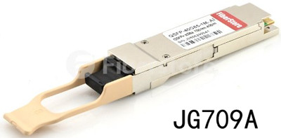
IEC 61754-7 and TIA/EIA 604-5 defined MPO connector that can accommodate up to 72 fibers in the tiniest of spaces, most commonly used for 12 or 24 fibers. This MPO connector is designed for the high-density connection of MMFs, allowing easy connection and disconnection. MPO connector has two alignment pins to align the ferrule, and a clamp spring. When closed, the MT connector is extremely compact and is thus well suited for high-density fiber connection within closures or cabinets. The kind of multi-mode connector combines high-density connection with convenient disconnecting action, ideal in satisfying the need for high-density packaging in equipment. In 40G links, QSFP+ transceivers use MPO connectors as the interface for high performance. Just like, this HP JG709A 40GBASE-CSR4 QSFP+ transceiver listed on FS.COM achieves 300m link length with MPO connector.

JG709A

Laser-optimized MMF OM3 and OM4 for 40G Solution

Category OM3 and OM4 MMF are the future-proof cabling choices for 40G links. Lasers are used for OM3 and OM4. These lasers are generally vertical-cavity surface-emitting lasers (VCSELs) which are cheaper than distributed feedback lasers. The VCSELs are able to transmit data at higher rates. According to the table shown above, OM3 has a link length of 100 meters so it supports about 85 percent of all data center channels depending on architecture and size, and OM4 fibers have a link length of 150 meters so they cover nearly 100 percent of the required reach.

Parallel Optical Channels in 40G Links

As noted in the table, the 802.3ba standard defines the parallel operation of four OM3/OM4 fibers for 40GbE in 40GBASE-SR4. Two fibers have to be used per link because this arrangement is full duplex operation, i.e. Simultaneous transmission in both directions. Therefore the number of fibers increases to eight for 40GBASE-SR4. That is four of the twelve fibers remain unused and eight of the twelve fibers are used in each case in connection with 12-fiber and MPO connectors. In the parallel optical link, the signal is split, transmitted over separate fibers and then joined again. That means the individual signals have to arrive at the receiver at the same time.

Conclusion

MPO/MTP technology is performance- and quality-assured as a trend for decision makers in to carefully plan their fiber optics infrastructure for 40GbE transmission. FS.COM provides not only high-quality MPOMTP connectors, but also MPO-based patch cables (eg. Push-Pull MPO cable). You can visit FS.COM for more information about MPO connectors and MPO-based cables.

MPO/MTP Technology Overview

Along with the development of fiber technologies over the past a couple of years, tools for easier fiber connection have been invented—fiber optic connectors (or so-called “better mousetrap”). Given there are various fiber optic connectors (eg. ST, SC, LC, MPO/MTP) available for network designers to set up fiber connectivity in bandwidth-demanding applications, this article introduces MPO/MTP in details.

MPO/MTP technology with multi-fiber connectors ensures ideal conditions for establishing high-performance and high-speed data networks to handle bandwidth requirements. The term MTP is a registered trademark of US Conec used to describe their connector. The US Conec MTP product is fully compliant with the MPO standards. As such, the MTP connector is a MPO connector. The following passages will mention MPO only instead of MPO/MTP for simplicity. To let readers gain a better understanding of MPO technology, MPO components introduction goes first followed by the applications of MPO technology.

MPO Components

MPO (multi-position optical) connector contains up to 24 fibers in a single connection. It’s available in a male version (with pins) or a female version (without pins). The pins ensure that the fronts of the connectors are exactly aligned on contact and that the endfaces of the fibers are not offset. MPO connector components mainly contain two parts: adapter and cable.

MPO Adapters

There are two types of MPO adapters based on the placement of the key: key-up to key-down, and key-up to key-up. In the former type, the key is up on one side and down on the other. The two connectors are connected turned 180° in relation to each other. In the latter type, both keys are up. The two connectors are connected in the same position in relation to each other. Just like what’s shown in the figure below.

MPO Cables

MPO fiber cables are available in two primary types: MPO trunk cables and MPO harness cables.

MPO trunk cables are available in 12-144 counts. They serve as a backbone connecting the MPO modules to each other, intended for high-density applications.

MPO harness cables, also called MPO breakout cables or MPO fanout cables, are available in 8-144 counts. As terminated with MTP/MPO connectors on one end and standard LC/FC/SC/ST/MTRJ connectors (generally MTP to LC) on the other end, MPO harness cables provide a transition from multi-fiber cables to individual fibers or duplex connectors.

MPO Applications: 10 GbE to 40 GbE/100 GbE Migration

The remaining parts describe how MPO technology is utilized to permit successful migration from 10 GbE to 40/100 GbE.

It’s no doubt that converting or expanding existing infrastructure to accommodate higher bandwidth applications is more ideal and practical in data centers. In 10 GbE to 40 GbE/100 GbE migration, the most key point that should be kept in mind is the capacity expansion in which MPO modules are used to enable faster transmission. Many 40G QSFP transceiver modules utilize MPO technology for 40G links, among which the Cisco QSFP is the most widely-used module. Take Cisco for example, QSFP-40G-SR4 realizes 40G links over 850nm multi-mode fiber (MMF) with MPO-12 as its connector type.

In 40G to 100G migration, there requires the use of 24-fiber MPO cables. The existing 12-fiber connection can either be expanded with the addition of a second 12-fiber connection or can be replaced with the installation of a 24 fiber connection.

Conclusion

With these MPO components and technology applications, it’s easier for network designers to select the right MPO types to meet the bandwidth requirements. As a professional fiber optical product manufacturer and supplier, FS supplies various MPO modules and cables, including QSFP-40G-SR4 (one of Cisco QSFP products) mentioned above. You can visit FS for more information about MPO modules.

The MPO and MTP Connectors For Plug-n-Play Systems

Today’s Data Centers are critical to the IT infrastructure of most large enterprises. Thanks to their quick-connect design, Plug-n-Play (PnP) fiber systems are becoming the prevalent choice for modern Data Centers. With Plug-n-Play, installation is fast and easy, and network downtime is minimized during expansions, scheduled maintenance, and emergency restoration procedures. The mainstays of modern PnP Systems are the relatively new multi-fiber connectors that allow for the interconnecting of several fibers at a time in a very dense footprint.

MPO stands for “Multi-Fiber Push On” and was originally designed by NTT. The design is based on the MT (mechanical transfer) ferrule. It is defined by the Telecommunications Industry Association’s (TIA) Fiber Optic Connector Intermateability (FOCIS 5) document, the TIA 604-5B Standard, and internationally by the IEC-61754-7 standard. The MTP connector is the “latest-generation MPO” connector with flaws fixed and features added to improve reliability and performance. Some improvements include lower insertion loss, the possibility of restoring the tip by polishing it, and the use of interferometers for better quality control(2). The MTP’s superior performance allows for optical insertion losses of 0.5dB or less. Figure 1 shows superior mechanical test performance results, another of the clear advantages of the MTP connector.

MTP

Both connectors are intermateable, meaning it is possible to connect an MTP to an MPO and vice-versa. Each connector will support some fibers, the most common being 12, while some versions are available with 24 fibers or even more. However, one should consider whether the space savings and easy connection convenience provided by connectors terminating more than 12 fibers will potentially impact reliability. Servicing a single fiber that may have been damaged will require the disconnecting of all other fiber channels linked through that connector. MTP and MPO connectors have guide pins to ensure proper fiber alignment and minimize optical insertion loss. These pins are present on the “male” connectors only. However, MTP connectors can be easily converted from “male” to “female” by removing the pins and, conversely, “female” to “male” by adding the pins.

Fiberstore has announced the release of a full suite of MPO MTP products designed to support the next generation of high-density fiber networks in data centers. The new product group includes MPO/MTP patch cables, trunk assemblies, fan-out assemblies, and related distribution hardware.

Fiberstore series rack-mounted patch panel is designed to manage and house easy-plug MTP/MPO to LC fiber cassette modules, for connecting plug-and-play pre-terminated high-density MTP / MPO Fiber cabling system. This solution contributes to greater network availability that is especially suitable for SAN, LAN, and Data Center applications. Each easy-plug MPO MTP cassette is accommodated with 12/24-fiber MTP / MPO-based fiber assemblies, and pre-loaded with LC adapters in different fiber modes for your choices.

FS High Fiber Count Plug-and-Play Trunks provide the backbone cabling for the TrueNet Plug-and-Play system. These high-count fiber trunk cables come pre-terminated with high-density MTP/MPO connectors on both ends and provide an easy and efficient way to pull large numbers of fibers at one time to help in the rapid deployment of the TrueNet Plug-and-Play system either in the data center or Local Area Network (LAN). Each fiber trunk cable has custom breakouts designed to work with ADC TrueNet Plug-and-Play connectivity. The FS High Fiber Count Trunks can simply be plugged into any plug-and-play cassette in the optical distribution frame or fiber enclosure which eliminates the need for on-site fiber termination and preparation.

Data Centers host expensive equipment and process very sensitive information for networks that must be always available. This level of reliability imposes stringent requirements on a Data Center’s infrastructure. A Data Center manager must be able to quickly perform adds, moves, and changes, as well as restorations in case of an outage. A very good analogy is a racecar making a pit stop and being serviced as quickly as possible.  In a data center hosting mission-critical applications, every second also counts. Therefore, the ability to quickly connect new equipment or service existing equipment is crucial. To accomplish this “quick-connect” capability, the fiber optics industry formulated a new de facto fiber standard, sometimes referred to as “Plug-n-Play” (PnP), based on an existing philosophy already adopted by many vendors in the computer industry. PnP systems are based on trunk cables, cassettes, harnesses, etc, which are comprised of pre-connectorized fiber optics elements.

Another solution for achieving quick connection is the use of multi-fiber connectors. By connecting several fibers at once, the installer or administrator saves a considerable amount of time. Since the time to connect a 12-fiber MTP connector is the same as to connect a single fiber connector (also called a discrete connector) one can make the same number of connections in roughly 1/12th the time. A common data center can easily reach 1,000 fiber terminations or more. Consequently, the time savings can be significant. Because PnP systems also allow for pre-engineered solutions, it is possible to determine cable lengths during the planning phase and, therefore, order only what is needed. This not only helps save money on fiber infrastructure but also helps to alleviate cable congestion under the raised floor. Since one of the main issues data center administrators have to face is cooling increasingly dense computing infrastructure, the use of a pre-engineered PnP system also helps to optimize cold air distribution. As previously mentioned, the building blocks of a PnP system are cable trunks, harnesses, PnP modules (often called cassettes), patch cords (also called jumpers), and accessories such as patch panels and enclosures. Multi-fiber connectors are present in virtually all these elements, and, along with small form factor connectors such as the LC, allow for reducing the “real estate footprint” in the data center. A solution using MTP and small form factor connectors can be almost twice as dense as a solution using previous-generation optical connectors. Therefore, more floor space is left available for mission-critical equipment such as switches, routers, servers, and storage.