Basic Knowledge About Fiber Optic Attenuator

It seems to be a commonplace for us to use an amplifier in fiber optic transmission which helps to improve signal electricity. However, it may occur sometimes that there is just too much light delivering through a fiber optic receiver and should better be reduced. In this case, a component known as fiber optic attenuator can help to reduce the power level of the signal. This article will focus on describing the fiber optic attenuator in details from the perspective of its types and applications.

What Is Fiber Optic Attenuator?

A fiber optic attenuator, generally known as optical attenuator, is a passive device used to reduce the power level of an optical signal. It can be adopted in both free space and in an optical fiber. Besides, to employ a fiber optic attenuator in single-mode long-haul application contributes to decreasing the chance of optical overload at the receiver.

By means of absorption, reflection, diffusion, scattering, deflection, diffraction and dispersion, etc, the fiber optic attenuator works efficiently to reduce the power of the signal. Optical attenuators usually function by absorbing the light, that resembles sunglasses absorb extra light energy. There exists a working wavelength range in which they absorb the light energy equally. They should not reflect the light since that could cause unwanted back reflection in the fiber system.

The Types of Fiber Optic Attenuator

There are a number of different forms of fiber optic attenuators by various classified methods, but basically, fixed attenuators and variable attenuators serve as the most common types that we can find in the market.

Fixed Attenuator

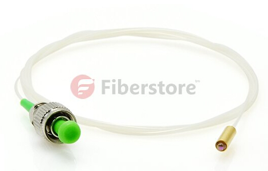
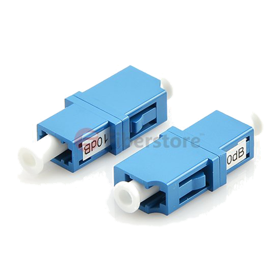
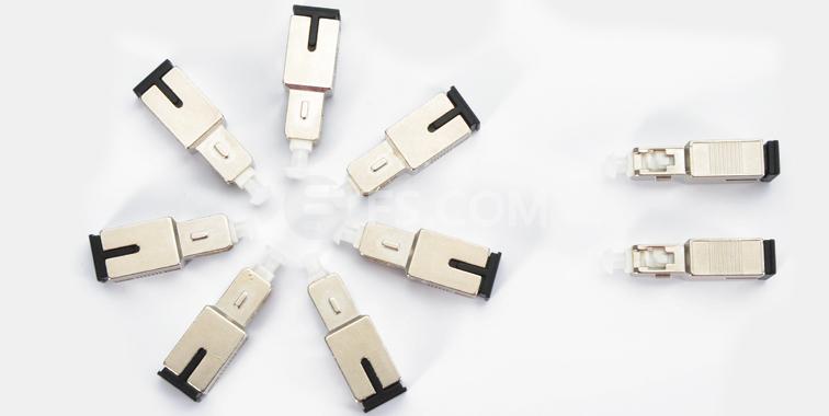
Fixed attenuator, as the name of which has indicated clearly, is designed to have an unchanging level of attenuation. It can theoretically be designed to provide any amount of attenuation that is desired. Fixed attenuator are typically used for single-mode applications and it consists of two groups: in-line type and connector type. In-line type appears like an ordinary fiber patch cable with a fiber terminated by two connectors. Connector type attenuator looks like a bulk head fiber connector, which has a male end and a female end as well. Fixed attenuator mates to regular connectors of the identical type such as FC, ST, SC and LC. The picture below shows a fixed male-female-SC/UPC SM 10dB fiber optic attenuator.

fixed attenuator

Variable Optical Attenuator

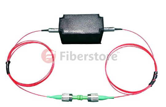
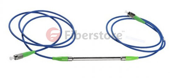
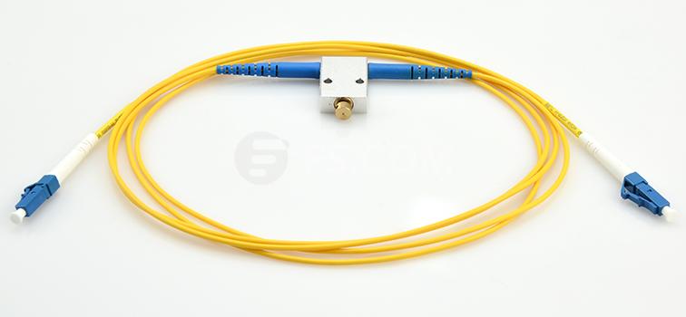
Variable optical attenuators generally use a variable neutral density filter. It has advantages of being stable, wavelength insensitive, mode insensitive, and offering a large dynamic range. Variable optical attenuator is generally used for testing and measurement, but it is also widely adopted in EDFAs (Erbium-Doped Fiber Amplifier) for equalizing the light power among different channels. Basically, there are two types of variable attenuators: stepwise variable attenuator and continuously variable attenuator. Stepwise variable attenuator can change the attenuation of the single in known steps such as 0.1 dB, 0.5 dB or 1 dB. Continuously variable attenuator produces precise level of attenuation with flexible adjustment. Thus, operators are able to adjust the attenuator to accommodate the changes required quickly and precisely without any interruption to the circuit. The following picture shows LC/UPC to LC/UPC variable fiber optic VOA in-line attenuator 0-60 dB.

variable optical attenuator

The Applications of Fiber Optic Attenuator

Fiber optic attenuator can be used to test power levels margins by temporarily adding a calibrated amount of signal loss. Besides, it is often installed permanently to properly match transmitter and receiver levels. And the sharp bends stress optic fibers and can cause losses.

Conclusion

From what we introduced above, you may have had a better understanding of the basic elements related to fiber optic attenuators. As an essential device in fiber optic transmission, it plays an indispensable role in controlling the power level of the optical signal. Those basic knowledge mentioned above may help provide a guideline to select the right fiber optic attenuator that matches the required applications precisely.

Fiberstore Passive Optical Components Solution

Passive optical components market is propelled by the accelerating bandwidth requirements coupled with the growth of passive optical network (PON). Usage of passive optical components to obtain energy efficient network solutions is gaining popularity. This article will introduce some Fiberstore passive optical components.

Optical Attenuators: an optical attenuator is a device that is used to reduce the power level of an optical signal. Optical attenuators are commonly used in fiber optic communications, either to test power level margins by temporarily adding a calibrated amount of signal loss, or installed permanently to properly match transmitter and receiver levels.

optical attenuators

Optical Circulator: an optical circulator is a multi-port (minimum three ports) non-reciprocal passive component. The function of an optical circulator is similar to that of a microwave circulator — to transmit a light wave from one port to the next sequential port with a maximum intensity, but at the same time to block any light transmission from one port to the previous port.

optical circulator

Fiber Collimator: a fiber collimator is a device for collimating the light coming from a fiber, or for launching collimated light into the fiber. It is used to expand and collimate the output light at the fiber end, or to couple light beams between two fibers. Both single-mode fiber collimators and multimode fiber collimators are available.

fiber collimator

Optical Isolator: an optical isolator is a passive optical component that allows light to propagate in only one direction. Optical isolators are typically used to protect light sources from back reflections or signals that can cause instabilities and damage. The operation of optical isolators depends on the Faraday effect, which is used in the main component, the Faraday rotator.

optical isolator

Fiber Optic Sensor: a fiber optic sensor is a sensor that uses optical fiber either as the sensing element (intrinsic sensors), or as a means of relaying signals from a remote sensor to the electronics that process the signals (extrinsic sensors). Fiber optic sensors are immune to electromagnetic interference, and do not conduct electricity so they can be used in places where there is high voltage electricity or flammable material such as jet fuel.

fiber optic sensor

Pump Combiner: a pump combiner is a passive optical component built based on fused biconical taper (FBT) technique. Pump combiners are widely used in fiber laser, fiber amplifier, high power EDFA, biomedical and sensor system etc. Three types of pump combiners are available: Nx1 Multimode Pump Combiner, (N+1)x1 Multimode Pump and Signal Combiner, PM(N+1)x1 PM Pump and Signal Combiner.

pump combiner

Polarization Components: polarization is the state of the e-vector orientation. Polarization components are used to isolate and transmit a single state of polarized light while absorbing, reflecting, and deviating light with the orthogonal state of polarization. Polarization components can be utilized in high power optical amplifiers and optical transmission system, test and measurement.

polarization components

Fiberstore has all of the above passive optical components with high quality and reasonable price. You can select excellent passive optical components or other optical products for your network at www.fs.com.

Guide to Optical Attenuators

Attenuators Overview

An optical attenuator, or fiber optic attenuator, is a device used to reduce the power level of an optical signal, either in free space or in an optical fiber. The optical attenuators can have a tuning control to set the level of attenuation into a range of selectable values (variable optical attenuators), or can introduce a fixed level of attenuation (fixed optical attenuators).

Variable optical attenuators are normally used for testing and measurement. Also they could be used in EDFAs (erbium doped fiber amplifier) for equalizing the light power among separate channels. Fixed optical attenuators have fixed values specified in decibels. The attenuation is expressed in dB and its value cannot be varied. It is ideal for attenuating single-mode fiber connectors in various applications.

Why Use Optical Attenuators?

Optical attenuators is a critical component of any fiber optic network. Using an attenuator, the transmission signal into the dynamic range of the receiver could be adjusted. This increases the life span of the optical equipment and ultimately provides a clearer transmission signal. Moreover, the utilization of optical attenuators could assure the linear behaviour of optical fiber receivers avoiding optical power overloading. At the same time, it is able to balance the optical power into passive optical network branches and can make measurements on an optical telecommunication system.

How Optical Attenuators Work?

Optical attenuators usually work by absorbing the light, like sunglasses absorb the extra light energy. Typically, they have a working wavelength range in which they absorb the light energy equally. However, they should not reflect the light since that could cause unwanted back reflection in the fiber system. Another type of attenuator utilizes a length of high-loss optical fiber, that operates upon its input optical signal power level in such a way that its output signal power level is less than the input level.

Application of Optical Attenuators

Optical attenuators are commonly used in fiber optic communications. They could be used to test power level margins by temporarily adding a calibrated amount of signal loss, or installed permanently to properly match transmitter and receiver levels.

One of the important applications of optical attenuators is channel balancing in WDMs (wavelength division multiplexing). As illustrated in the following picture, an eight channel wavelength multiplexed signal from a trunk line is demultiplexed into individual signals. The signals are of different intensities, and need to be balanced to avoid saturating any of the receivers. So each channel is sent through a corresponding port on an eight channel MEMS (micro-electro-mechanical systems) VOA (variable optical attenuator). The signal strength through the optical attenuator outputs is monitored by a control circuit. If the output signal gets too high or too low, the corresponding optical attenuator is adjusted to bring the light level to the correct range.

optical attenuator in WDM network

As stated above, an optical attenuator is used to reduce the power level when there is too much light deliver through a fiber optic receiver. It is used to adjust optical signal levels thereby increasing network flexibility and providing management of optical power. If you are looking for an optical attenuator, Fiberstore is a primary option. It has many different fixed optical attenuators and variable optical attenuators including fixed LC/APC fiber optic attenuator, fixed SC/UPC fiber optic attenuator, BVA610 optical variable attenuator(0-60dB), etc. For more information, you can visit www.fs.com.

How to Test the Sensitivity of a Fiber Optic Receiver by using an Optical Attenuator

Knowing how to test the sensitivity of a fiber optic receiver is an important skill. A fiber optic receiver provides optimal performance when the optical input power is within a certain range. But how do you test the receiver to see if it will provide optimal performance at the lowest optical input powers? One way is to use Optical Attenuators, such as bulkhead attenuators. Typically only a couple of values are required to complete your testing. This process involves three steps shown as following.

  1. Measure the optical output power of the fiber optic transmitter with the power meter. Remember that industry standards define transmitter optical output power and receiver optical input power for a particular network standard. If you are testing a 100BASE-FX receiver, you should be using a 100BASE-FX transmitter. The optical output power of the transmitter should be within the range defined by the manufacturer’s data sheet.
  2. Connect the transmitter to the receiver and verify proper operation at the maximum optical output power that the transmitter can provide. You need to test the receiver at the minimum optical input power that the receiver can accept while still providing optimal performance. To do this, you need to obtain the lowest optical input power level value from the manufacturer’s data sheet.
  3. Calculate the attenuation level required for the test. For example: The transmitter’s optical output power is -17 dBm and the minimum optical power level for the receiver is -33 dBm. The difference between them is 16 dB. You would use a 16 dB bulkhead attenuator at the input of the receiver and retest the receiver. If the receiver still operates properly, it’s within specifications.

Note: The optical loss is not considered about in the example above. Suppose that the transmitter is located 10 km from the receiver and the loss for the whole optical fiber link (including interconnections) is 6 dB, then you should use a 10 dB bulkhead attenuator rather than the 16 dB one for your test.

10dB Bulkhead Attenuator

This article source is from fiberopticshare blog.