As large-scale data centers transition to faster and more scalable infrastructures and with the rapid adoption of hyperscale cloud infrastructures and services, existing 100G networks fall short in meeting current demands. As the next-generation mainstream port technology, 400G significantly increases network bandwidth, enhances link utilization, and assists operators, OTT providers, and other clients in effectively managing unprecedented data traffic growth.
To meet the demand for higher data rates, FS has been actively developing a series of 400G products, including 400G switches, optical modules, cables, and network adapters.
FS 400G Switches
The emergence of 400G data center switches has facilitated the transition from 100G to 400G in data centers, providing flexibility for building large-scale leaf and spine designs while reducing the total number of network devices. This reduction can save costs and decrease power consumption. Whether it’s the powerful N9510-64D or the versatile N9550 series, FS 400G data center switches can deliver the performance and flexibility required for today’s data-intensive applications.
Of particular note is that, as open network switches, the N8550 and N9550 series switches can enhance flexibility by freely choosing preferred operating systems. They are designed to meet customer requirements by providing comprehensive support for L3 features, SONiC and Broadcom chips, and data center functionalities. Additionally, FS offers PicOS-based open network switch operating system solutions, which provide a more flexible, programmable, and scalable network operating system (NOS) at a lower total cost of ownership (TCO).
FS 400G Transceivers
FS offers two different types of packaging for its 400G transceivers: QSFP-DD and OSFP, developed to support 400G with performance as their hallmark. Additionally, FS provides CFP2 DCO transceivers for coherent transmission at various rates (100G/200G/400G) in DWDM applications. Moreover, FS has developed InfiniBand cables and transceivers to enhance the performance of HPC networks, meeting the requirements for high bandwidth, low latency, and highly reliable connections.
FS conducts rigorous testing on its 400G optical modules using advanced analytical equipment, including TX/RX testing, temperature measurement, rate testing, and spectrometer evaluation tests, to ensure the performance and compatibility of the optical modules.
FS 400G Cables
When planning 400G Ethernet cabling or connection schemes, it’s essential to choose devices with low insertion loss and good return loss to meet the performance requirements of high-density data center links. FS offers various wiring options, including DAC/AOC cables and breakout cables. FS DAC/AOC breakout cables provide three connection types to meet high-density requirements for standard and combination connector configurations: 4x100G, 2x200G, and 8x50G. Their low insertion loss and ultra-low crosstalk effectively enhance transmission performance, while their high bend flexibility offers cost-effective solutions for short links.
FS 400G Network Adapters
FS 400G network adapters utilize the industry-leading ConnectX-7 series cards. The ConnectX-7 VPI card offers a 400Gb/s port for InfiniBand, ultra-low latency, and delivers between 330 to 3.7 billion messages per second, enabling top performance and flexibility to meet the growing demands of data center applications. In addition to all existing innovative features from previous versions, the ConnectX-7 card also provides numerous enhanced functionalities to further boost performance and scalability.
FS 400G Networking Soluitons
To maximize the utilization of the 400G product series, FS offers comprehensive 400G network solutions, such as solutions tailored for upgrading from 100G to high-density 400G data centers. These solutions provide diverse and adaptable networking options customized for cloud data centers. They are designed to tackle the continuous increase in data center traffic and the growing need for high-bandwidth solutions in extensive 400G data center networks.
In the era of ultra-high-speed data transmission, MTP/MPO cables have become a key player, especially in the context of 800G networks. In essence, MTP/MPO cables emerge as catalysts for the evolution toward 800G networks, offering a harmonious blend of high-density connectivity, reliability, and scalability. This article will delve into the advantages of MTP/MPO cables in 800G networks and provide specific solutions for constructing an 800G network, offering valuable insights for upgrading your existing data center.
Challenges Faced in 800G Data Transmission
As a critical hub for storing and processing vast amounts of data, data centers require high-speed and stable networks to support data transmission and processing. The 800G network achieves a data transfer rate of 800 Gigabits per second (Gbps) and can meet the demands of large-scale data transmission and processing in data centers, enhancing overall efficiency.
Therefore, many major internet companies are either constructing new 800G data centers or upgrading existing data centers from 100G, 400G to 800G speeds. However, the pursuit of 800G data transmission faces numerous complex challenges that necessitate innovative solutions. Here, we analyze the intricate obstacles associated with achieving ultra-fast data transmission.
Insufficient Bandwidth & High Latency
The 800G network demands extensive data transmission, placing higher requirements on bandwidth. It necessitates network equipment capable of supporting greater data throughput, particularly in terms of connection cables. Ordinary optical fibers typically consist of a single fiber within a cable, and their optical and physical characteristics are inadequate for handling massive data, failing to meet the high-bandwidth requirements of 800G.
While emphasizing high bandwidth, data center networks also require low latency to meet end-user experience standards. In high-speed networks, ordinary optical fibers undergo more refraction and scattering, resulting in additional time delays during signal transmission.
Limited Spatial Layout
The high bandwidth requirements of 800G networks typically come with more connection ports and optical fibers. However, the limited space in data centers or server rooms poses a challenge. Achieving high-density connections requires accommodating more connection devices in the constrained space, leading to crowded layouts and increased challenges in space management and design.
Complex Network Architecture
The transition to an 800G network necessitates a reassessment of network architecture. Upgrading to higher data rates requires consideration of network design, scalability, and compatibility with existing infrastructure. Therefore, the cabling system must meet both current usage requirements and align with future development trends. Given the long usage lifecycle of cabling systems, addressing how to match the cabling installation with multiple IT equipment update cycles becomes a challenging problem.
High Construction Cost
Implementing 800G data transmission involves investments in infrastructure and equipment. Achieving higher data rates requires upgrading and replacing existing network equipment and cabling management patterns, incurring significant costs. Cables, in particular, carry various network devices, and their required lifecycle is longer than that of network equipment. Frequent replacements can result in resource wastage.
Effectively addressing these challenges is crucial to unlocking the full potential of a super-fast, efficient data network.
The significance of MTP/MPO cables in high-speed networks, especially in 800G networks, lies in their ability to manage the escalating data traffic efficiently. The following are key advantages of MTP/MPO cables:
High Density, High Bandwidth
MTP/MPO cables adopt a high-density multi-fiber design, enabling the transmission of multiple fibers within a relatively small connector. This design not only provides ample bandwidth support for data centers, meeting the high bandwidth requirements of an 800G network, but also helps save space and supports the high-density connection needs for large-scale data transfers.
Additionally, MTP/MPO cables exhibit excellent optical and mechanical performance, resulting in low insertion loss in high-speed network environments. By utilizing a low-loss cabling solution, they effectively contribute to reducing latency in the network.
Flexibility and Scalability
MTP/MPO connectors come in various configurations, accommodating different fiber counts (8-core, 12-core, 16-core, 24-core, etc.), supporting both multimode and single-mode fibers. With trunk and breakout designs, support for different polarities, and male/female connector options, these features allow seamless integration into various network architectures. The flexibility and scalability of MTP/MPO connectors enable them to adapt to evolving network requirements and facilitate future expansions, particularly in the context of 800G networks.
Efficient Maintenance
The high-density and compact design of MTP/MPO cables contribute to saving rack and data room space, enabling data centers to utilize limited space resources more efficiently. This, in turn, facilitates the straightforward deployment and reliable operation of 800G networks, reducing the risks associated with infrastructure changes or additions in terms of cost and performance. Additionally, MTP/MPO cables featuring a Plenum (OFNP) outer sheath exhibit fire resistance and low smoke characteristics, minimizing potential damage and saving on cabling costs.
Scaling the 800G Networks With MTP/MPO Cables
In the implementation of 800G data transmission, the wiring solution is crucial. MTP/MPO cables, as a key component, provide reliable support for high-speed data transmission. FS provides professional solutions for large-scale data center users who require a comprehensive upgrade to 800G speeds. Aim to rapidly increase data center network bandwidth to meet the growing demands of business.
Newly Built 800G Data Center
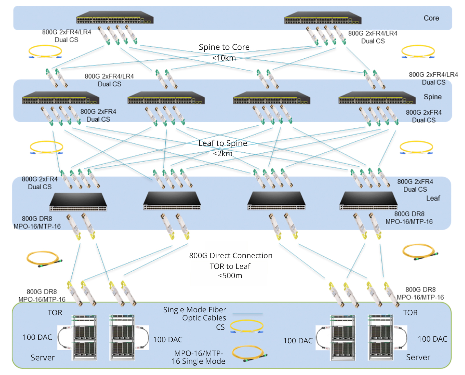
Given the rapid expansion of business, many large-scale internet companies choose to build new 800G data centers to enhance their network bandwidth. In these data centers, all network equipment utilizes 800G switches, combined with MTP/MPO cables to achieve a direct-connected 800G network. To ensure high-speed data transmission, advanced 800G 2xFR4/2xLR4 modules are employed between the core switches and backbone switches, and 800G DR8 modules seamlessly interconnect leaf switches with TOR switches.
To simplify connections, a strategic deployment of the 16-core MTP/MPO OS2 trunk cables directly connects to 800G optical modules. This strategic approach maximally conserves fiber resources, optimizes wiring space, and facilitates cable management, providing a more efficient and cost-effective cabling solution for the infrastructure of 800G networks.
Upgrade from 100G to 800G
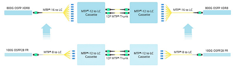
Certainly, many businesses choose to renovate and upgrade their existing data center networks. In the scenario below, engineers replaced the original 8-core MTP/MPO-LC breakout cable with the 16-core version, connecting it to the existing MTP cassettes. The modules on both ends, previously 100G QSFP28 FR, were upgraded to 800G OSFP XDR8. This seamless deployment migrated the existing structured cabling to an 800G rate. It is primarily due to the 16-core MTP/MPO-LC breakout cable, proven as the optimal choice for direct connections from 800G OSFP XDR8 to 100G QSFP28 FR or from 800G QSFP-DD/OSFP DR8 to 100G QSFP28 DR.
In short, this solution aims to increase the density of fiber optic connections in the data center and optimize cabling space. Not only improves current network performance but also takes into account future network expansion.
Elevating from 400G to the 800G Network
How to upgrade an existing 400G network to 800G in data centres? Let’s explore the best practices through MTP/MPO cables to achieve this goal.
Based on the original 400G network, the core, backbone, and leaf switches have all been upgraded to an 800G rate, while the TOR (Top of Rack) remains at a 400G rate. The core and backbone switches utilise 800G 2xFR4/2xLR4 modules, the leaf switches use 800G DR8 modules, and the TOR adopts 400G DR4 modules. Deploying two 12-core MTP/MPO OS2 trunk cables in a breakout configuration between the 400G and 800G optical modules facilitates interconnection.
Furthermore, there is a second connectivity option where the 800G port optical module utilises OSFP SR8, the 400G port uses OSFP SR4 optical module, and the intermediate cables are connected using 12-core MTP® OM4 trunk cables.
These two cabling solutions enhance scalability, prevent network bottlenecks, reduce latency, and are conducive to expanding bandwidth when transitioning from lower-speed to higher-speed networks in the future. Additionally, this deployment retains the existing network equipment, significantly lowering cost expenditures.
Ultimately, the diverse range of MTP/MPO cable types provides tailored solutions for different connectivity scenarios in 800G networks. As organizations navigate the complexities of high-speed data transmission, MTP/MPO cables stand as indispensable enablers, paving the way for a new era of efficient and robust network infrastructures.
How FS Can Help
The comprehensive networking solutions and product offerings not only save costs but also reduce power consumption, delivering higher value. Considering an upgrade to 800G for your data center network? FS tailors customized solutions for you. Don’t wait any longer—Register as an FS website member now and enjoy free technical support.
Optical fiber cables have become one of the key points in the 5G competition. It’s known that 5G networks will offer consumers high-speed and low-latency services with more reliable and stronger connections. But to make this happen, more 5G base stations have to be built due to the higher 5G frequency band and limited network coverage. And it’s estimated that by 2025, the total number of global 5G base stations will reach 6.5 million, which puts forward higher requirements for the optical fiber cable performance and production.
Currently, there are still some uncertainties in 5G network architectures and the selection of technical solutions. But in the basic physical layer, the 5G fiber cables should meet both current application and future development needs. The following are five types of optical fiber cables that address problems in 5G networks built to some degree.
1. Bend Insensitive Optical Fiber for Easy 5G Indoor Micro Base Stations
The dense fiber connections between massive 5G new macro base stations and indoor micro base stations are the main challenge in the 5G access network constructions. The complex cabling environments, especially the indoor fiber cabling, and the limited space and bend request high requirements for the fiber bend performance. Optical fiber compliant ITU G.657.A2/B2/B3 has great bend-improved performance, which can be stapled and bent around corners without sacrificing performance.
Many fiber manufacturers have announced bend-insensitive fiber (BIF) cables with low loss to address such problems in 5G indoor applications.
Company
Product Name
ITU Standards
Bend Radius (1 turn around a mandrel)
Induced Attenuation (dB)
Corning
ClearCurve LBL fiber
G.652.D, G.657.A2/B2
7.5 mm
≤ 0.4
YOFC
EasyBand® Ultra BIF
G.652.D, G.657.B3
5 mm
≤ 0.15
Prysmian Group
BendBright XS fiber
G.652.D, G.657.A2/B2
7.5 mm
≤ 0.5
Note: The induced attenuation is caused due to fiber wrapped around a mandrel of a specific radius.
2. OM5 Multimode Fiber Applied to 5G Core Networks
5G service providers also have to focus on the fiber optic network build of the data centers where the content is stored. At present, the transmission speed of data centers is evolving from 10G/25G, 40G/I00G to 25G/I00G, 200G/400G, which put forward new requirements for the multimode optical fibers used for interconnection inside the data centers. Multimode optical fibers need to compatible with the existing Ethernet standard, cover the future upgrades to higher speed like 400G and 800G, support multi-wavelength multiplexing technologies like SWDM and BiDi, and also need to provide excellent bending resistance to adjust to dense data centers cabling scenarios.
Figure 1: OM5 fiber in 100G BiDi and 100G SWDM applications
Under such conditions, the new broadband OM5 multimode fiber becomes the hotspot option for data center constructions. OM5 fiber allows multiple wavelengths to be transmitted simultaneously in the vicinity of 850 nm to 950 nm. By adopting the PAM4 modulation and WDM technology, OM5 optical fiber is able to support 150 meters in 100Gb/s, 200Gb/s, and 400Gb/s transmission systems, and ensure the ability of future short-distance and high-speed transmission networks, making it the optimal choice for intra-data center connections under the 5G environment.
Here is a comparison of the link length of OM5 and other multimode fiber over 850nm wavelength.
Link Length (M) @850nm wavelength
Fiber Type
10GBASE-SR
25GBASE-SR
40GBASE-SR4
100GBASE-SR4
400GBASE-SR16
400GBASE-SR8
400GBASE-SR4.2
OM3
300
70
100
70
100
70
70
OM4
550
100
150
100
150
100
100
OM5
550
100
150
100
150
100
150
3. Micron Diameter Optical Fibers Enable Higher Fiber Density
Due to the complex deployment environments of the access layer or aggregation layer of 5G bearer networks, it’s easy to encounter problems like the limited existing cable pipeline resources. To ensure the limited space can hold more optical fibers, cable manufacturers are working hard to reduce the size and diameter of cable bundles. For example, recently the Prysmian Group has introduced the BendBright XS 180µm single-mode fiber to meet the 5G technology demands. This innovative optical fiber enables cable designers to offer strongly reduced cable dimensions while still keeping the 125µm glass diameter.
Figure 2: Prysmian’s BendBright XS 180µm fiber
Similarly, with the same principles, Corning has introduced the SMF-28 Ultra 200 fiber that allows fiber cable manufacturers to shave 45 microns off previous cable coating thicknesses, going from 245 microns down to 200 microns, to achieve a smaller overall outer diameter. And YOFC, another optical fiber manufacturer, also provides EasyBand plus-Mini 200μm reduced diameter bending insensitive fiber for 5G networks, which can reduce the cable diameter by 50% and significantly increase the fiber density in pipelines when compared with common optical fibers.
4. ULL Fiber with Large Effective Area Can Extend 5G Link Length
5G fiber manufacturers are actively exploring ultra low-loss (ULL) optical fiber technologies to extend the fiber reach as long as possible. The G.654.E optical fiber is such a type of innovative 5G fiber. Different from the common G.652.D fiber often used in 10G, 25G, and 100G, the G.652.E fiber comes with a larger effective area and ultra-low loss features, which can significantly reduce the nonlinear effect of optical fiber and improve the OSNR that are easily affected by higher signal modulation format in 200G and 400G connections.
Speed (bps)
40G
100G
400G
400G
Fiber Type
common G.652
low-loss G.652
low-loss G.652
innovative G.654.E
Maximum Capacity (Tbs)
3.2
8
20
20
Limit Relay Distance (km)
6000
3200
<800
<2000
Typical Link Attenuation (dB/km)
0.21
0.20
0.20
0.18
Fiber Effective Area (µm²)
80
80
80
130
With the continuous increase of the transmission speed and capacity of the 5G core network and the clouded data center, fiber optic cables like this will be needed more. It’s said that the latest Corning’s TXF fiber, a type of G.654.E fiber, comes with high-data-rate capabilities and exceptional reach, able to help network operators deal with growing bandwidth demands while lowering their overall network costs. Recently, Infinera and Corning have achieved 800G across 800km using this TXF fiber, which shows this fiber is expected to offer excellent long-haul transmission solutions for 5G network deployment.
5. Optical Fiber Cable for Faster 5G Network Installation
5G network deployment covers both indoor and outdoor scenarios, the installation speed is a factor needed to consider. Full-dry optical cable using dry water-blocking technology is able to improve fiber splicing speed during cable installation. Air-blown micro cables are compact and lightweight and contain high fiber density to maximize the fiber count. This type of cable is easy to be installed in longer ducts with multiple bends and undulations, and it can save in manpower & installation time and improved installation efficiency via the blowing installation methods. For the outdoor fiber cable deployment, some anti-rodent and anti-bird optical cables also need to be used.
Get Ready for 5G Networks
Currently, optical fiber is the optimal medium capable of scaling to the 5G demands. 5G networks’ enhanced bandwidth capacity, lower latency requirements and complicated outdoor deployments bring challenges as well as unlimited possibilities for optical fiber manufacturers, but our optical networks must quickly adapt to meet such new demands. Except for the optical fiber mentioned above, it remains to be seen if the 5G fiber manufacturers will put forward other innovative fiber for the market as quickly as possible.
An optical fiber cable uses light wave for voice and data transmission, its data transmission capacity is 4.5 times more than conventional copper cables. So in the past several decades, we have seen that fiber optic cables are superior to traditional copper twisted-pair cable or coaxial cable because of its unique physical characteristics, allowing information to travel at speeds increasingly approaching the speed of light without interference between adjacent wavelengths. In leading market, the global drive to implement FTTx into more new venues is good news for the market of optical fiber cables. Another good trend is that the price erosion of optical fiber cables had been 10 to 15 percent annually, in result that the demand of optical fiber cable is expected to continue growing in the foreseeable future. And the growing data transmission workloads placed by high-performance computers, servers and network storage systems is helping spur growth in the market. Consequently, fiber optic cables are now the indispensable backbone of today’s communication network. This article will analyse the global optical fiber cable market in three main applications, including long-distance communication, submarine cable and FTTx network.
Global Optical Fiber Cable Market to Grow at 9.8% till 2021
According to the report “Fiber Optics Market by Cable – Global Forecast to 2021”, the optical fiber cable market is anticipate to grow at a CAGR of over 9.8% during 2016-2021. The growing importance of cloud computing, data transfer & storage, and IoT is driving the use of Internet, which is driving the fiber optic cable market, as it acts as the backbone for data transmission. Moreover, growing technological advancements increase in number of connected devices and data centers are expected to positively influence global optical fiber cable market. In addition, next generation technologies such as LTE and FTTx, which require last mile connectivity, is expected to propel the demand for optical fiber cables in the coming years. All these factors have led to an increase in Internet users, which in turn has led to the higher usage of optical fiber cable to transfer information over the Internet, thus driving the fiber optics market.
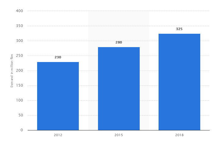
Global Optical Fiber Cable Demand from 2012 to 2018 (Source: Statista)
Optical Fiber Cable Market in Long-distance Communication
Currently, the growing adoption of optical technology in the telecommunications appears to be promising. Optical fiber has virtually unlimited capacity and low signal attenuation allowing long distances without amplifier or repeater, no exposure to parasite signals or crosstalk, and no electromagnetic interference (EMI). So fiber optic cable is especially advantageous for high-speed data transfer services in long-distance communications over electrical cabling. Furthermore, the increasing cloud-based applications, audio-video services, and Video-on-Demand (VoD) services further stimulate the demand for optical fiber cable installations.
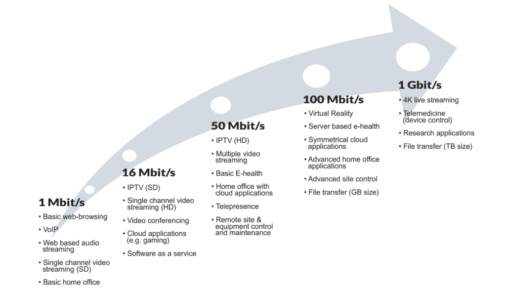
Growing Need for Capacity (Source: Goldmedia)
Submarine Optical Fiber Cable Market
Submarine optical fiber cables are undersea cables used for carrying data across interconnected networks between continents. With the advancements of technology, most of the submarine optical fiber cables that currently form the backbone of the Internet connect the U.S. to Europe and Asia by crossing the Atlantic or Pacific oceans. Instead, there is a proposal for deployment of Trans-polar submarine cable system in Arctic Ocean. Laying an undersea fiber optic cable is meant to connect Asia and Europe by crossing the Arctic Circle – the shortest practical distance yet for Internet signals traveling between the two continents. According to the report by Global Industry Analysts (GIA), cumulative installations of submarine optical fiber cables globally are projected to reach 2 million kilometers by 2020, driven by the growing demand for fiber broadband and the ensuing deployment of fiber optic cables in the Internet backbone. Presently, submarine optical fiber cables transmit 100% of the international Internet traffic, and more than 95% of the world’s combined data and voice traffic.
In recent years, the market for optical fiber cable has shifted dramatically to local deployments, away from long haul and regional. This is the impact of FTTx, which calls for far more dense applications in neighborhoods, cities and other highly focused areas. Optical fiber cable is being caught up in the global move to broadband in the near future. The next generation of high bandwidth applications, along with the proliferation of connected devices, is expected to require faster and higher bandwidth networks which will require the use of multimode fiber cable for data transfer. This growth in the FTTx networks in turn is expected to drive the fiber optics market. Future Market Insights (FMI) forecasts the global fiber to the home (FTTH) market’s value will grow from $9.5 billion in 2017 to more than $37 billion by the end of 2027, a 14.4% compound annual growth rate (CAGR). In the leading Asian economies, more than 44% of all homes and buildings are already directly connected to the fiber optic cable network; in North America penetration is 8.4%, in Europe 5.6%.
Final Thought
Fiber optic cable is widely used for data transmission and is increasingly being used in place of metal wires because of its efficiency and high transmission capacity. Since the use and demand for great bandwidth and fast speed, there is no doubt that fiber optic transmission will bring more opportunities and be continuously researched and expanded to cater for future demands. However, although fiber optic cable in itself is considered a long-term stable investment, it also faces huge challenge. The major restraint in the fiber optics market is the growing use of wireless communications systems in remote areas.
The 100BASE-FX fiber optic media system provides all of the advantages of a 10BASE-FL fiber optic link segment, while operating ten times faster. Distances of 2 km (6561.6 feet) over multimode fiber optic cables are possible when operating 100BASE-FX segments in full-duplex mode. Considerably longer distances are possible when using single mode fiber segments. This is why the 100BASE-FX media system is a popular choice for Ethernet backbone networks. The following set of media components are used to build a 100BASE-FX fiber optic segment:
● Fiber optic cable.
● Fiber optic connectors.
Fiber Optic Cable
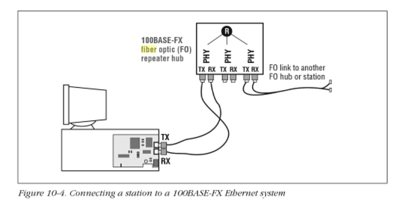
The 100BASE-FX specification requires two strands of multimode fiber optic (MMF) cable per link, one for transmit data, and one for receive data, with the signal crossover (TX or RX) performed in the link as shown in Figure 10-4. There are many kinks of fiber optic cables available, ranging from simple two-strand jumper cables with PVC plastic for the outer jacket material on up to large inter-building cables carrying many fibers in a bundle.
The typical fiber optic cable used for a 100BASE-FX fiber link segment consists of a graded-index MMF cable. These fibers optic cables have a 62.5 um fiber optic core and 125um outer cladding (62.5/125). The wavelength of light used on a 100BASE-TX fiber link segment is 1350 nanometers (nm). Signals sent at that wavelength over MMF fiber can provide segnment lengths of up to 2000 meters (6561 feet) when operating the link in full-duplex mode. More details on installing and using fiber optic cables and connectors can be found, Fiber optic cables and connectors.
Fiber Optic Connector
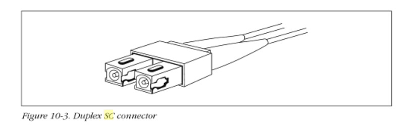
The medium-dependent interface (MDI) for a 100BASE-FX link may be one of three kinks of fiber optic connector. Of the three, the duplex SC connector shown in Figure 10-3 is the recommended alternative in the standard an is the one most widely used gy vendors. The SC connector is designed for ease of use; the connector is pushed into place and automatically snaps into the connector housing to complete the connection.
The ST connector may also be used. This is the same connector used for a 10BASE-FL link. It is a spring-loaded bayonet-type connector that has a key on an inner sleeve and an outer baynoet ring. To make a connection, you line up the key on the inner sleeve of the ST plug with a corresponding slot on the ST receptacle, then push the connector in and lock it in place by twisting the outer bayonet ring. According to the standard, the FFDI fiber optic media interface connector (MIC) may also be used on 100BASE-FX equipment: however, this optional connector has not been adopted by equipment vendors.
Connecting a Station to 100BASE-FX Ethernet
Figure 10-4 shows a computer equipped with a 100BASE-FX Ethernet adapter. In this example, the adapter card comes with an SC duplex connector, which makes a connection to the fiber cables that connect to the repeater hub. The repeater hub in the figure is shown with three pairs of 100BASE-FX SC connectors and built-in transceivers. A signal crossover is required to make a connection between the 100BASE-FX transceiver in the station, and the 100BASE-FX transceiver located in each repeater or switching hub port.
Fiberstore as the main professional fiber optic products manufacturer in china offer a various kinds of fiber cable connectors, FC Connectors, LC Connectors, SC Connectors, MPO Connectors and ST Connectors. You can buy fiber optic connection products on our store with your confidence. All of fiber optics supplies with high quality but low price. Except fiber optic connector, we provide various types of fiber patch cords including single mode, multimode, multi core, and armored versions. You can aslo find fiber optic pigtails and other special patch cables here. For most of them, the SC, ST, FC, LC, MU, MTRJ, E2000, APC/UPC connectors are all available, even we supply MPO/MTP fiber cables.
A fiber optic cable is a network cable that contains strands of glass fibers inside an insulated casing. These fiber optic cables are designed for long distance and very high bandwidth network communications. The optical fiber elements are typically individually coated with plastic layers and contained in a protective tube suitable for the environment where the cable will be deployed. Different types of cable are used for different applications, for example long distance telecommunication, or providing a high speed data connection between different parts of a building.
Fiber optic cables carry communication signals using pulses of light. While expensive, these cables are increasingly being used instead of traditional copper cables, because fiber offers more capacity and is less susceptible to electrical interference. So called Fiber To The Home (FTTH) installations are becoming more common as a way to bring ultra high speed Internet service to residences.
What are the color codes for fiber optic cable?
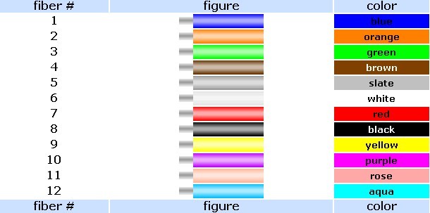
The fibers in optical fiber cables are numbered according to their color code, which simplifies connecting hardware installation and connector termination as well as further administration and testing of the cabling system.
The fibers are numbered in accordance with the individual standard color code given in figure 1. 250- and 900-micron buffer coatings are subject to color-coding. In modular design multifiber cables, the same color coding is applied with respect to modules.
In loose tube cables, with over 12 fibers in one tube, fibers can be combined to form a single unit fixed by colored threads.
In some cases to facilitate pair grouping the fibers are painted the same colors with collar marks every 2-3 cm (0.8 – 1.2 in) on the second fiber of the pair.
Colored outer jackets or print may be used on Premises Distribution Cable, Premises Interconnect Cable or Interconnect Cord, or Premises Breakout Cable to identify the classification and fiber sizes of the fiber.
When colored jackets are used to identify the type of fiber in cable containing only one fiber type, the colors shall be as indicated in Table 1. Other colors may be used providing that the print on the outer jacket identifies fiber classifications in accordance with subclause 4.3.3. Such colors should be as agreed upon between manufacturer and user.
Unless otherwise specified, the outer jacket of premises cable containing more than one fiber type shall use a printed legend to identify the quantities and types of fibers within the cable. Table 3 shows the preferred nomenclature for the various fiber types, for example “12 Fiber 8 x 50/125, 4 x 62.5/125.”
When the print on the outer jacket of premises cable is used to identify the types and classifications of the fiber, the nomenclature of Table 3 is preferred for the various fiber types. Distinctive print characters for other fiber types may be considered for addition to Table 1 at some future date.
Notes:
1. Natural jackets with colored tracers may be used instead of solid-color jackets.
2. Because of the limited number of applications for these fibers, print nomenclature are to be agreed upon between manufacturer and end-user.
3. Other colors may be used providing that the print on the outer jacket identifies fiber classifications.
4. For some premises cable functional types (e.g, plenum cables), colored jacketing material may not be available. Distinctive jacket colors for other fiber types may be considered for addition at some future date.
How does a fiber optic cable work?
To understand how a fiber optic cable works, imagine an immensely long drinking straw or flexible plastic pipe. For example, imagine a pipe that is several miles long. Now imagine that the inside surface of the pipe has been coated with a perfect mirror. Now imagine that you are looking into one end of the pipe. Several miles away at the other end a friend turns on a flashlight and shines it into the pipe. Because the interior of the pipe is a perfect mirror, the flashlight’s light will reflect off the sides of the pipe (even though the pipe may curve and twist) and you will see it at the other end. If your friends were to turn the flashlight on and off in a morse code fashion, your friend could communicate with you through the pipe. That is the essence of a fiber optic cable.
Transmitter
A transmitter is a device found at the beginning of a fiber optic cable network. The transmitter takes information and turns it into a pulsing light wave that can be sent along a fiber optic cable. A lens is then used to send the light into a fiber optic cable. The light will travel along the fiber optic cables more quickly and with less signal degradation than occurs when sending data along traditional coper wires.
Fiber Optic Cable
The core of a fiber optic cable is made of a very clear glass tube that transmits light. This glass core is surrounded by a coating called cladding. Light will travel down the fiber optic tube in a straight line. Unfortunately, not all fiber optical cables can be laid along a straight path, so the cladding surrounding the cable is mirrored. The light bounces off of the mirrors on the cladding and is directed back into the fiber optic core to continue its journey along the cable.
Optical Regenerator
Sometimes a light signal must travel through a fiber optic cable over a very long distance. Although signal degradation is minimal in a fiber optic cable, some degradation does occur. When a cable covers a long distance, optical regenerators are placed at certain intervals along the cable. Optical regenerators are fibers that have been treated with a laser. The molecules in the fiber allow the signal traveling through the fiber optic cable to take on laser properties themselves, which strengthens the light signal. Optical regenerators essentially strengthen the light signal that is traveling through a fiber optic cable.
Optical Receiver
At the end of the fiber otic network there is an optical receiver. This receiver is essentially performs the opposite function of the transmitter found at the beginning of the system. Optical receivers receive the light signal from the fiber optic cable and turn it back into information that a computer or television know how to understand and use. It then sends the decoded signal to the computer or television.
Types of loose tube fiber optic cables
FiberStore have many types of loose tube fiber optic cables, such as All -Dielectric Loose Tube Cables, Gel-Filled Loose Tube Cables, Double-Jacket Loose Tube Cables, Central Loose Tube Cables.
FiberStore provide OTDR JDSU MTS-2000 tester by US$ 4,050.00 for sale.The price is very resonable.The MTS-2000 is the smallest and the most mobile and compact test platform designed to test all phases of the fiber optic network lifecycle, from the installation to the maintenance of Access and FTTx networks. Working with the same optical module than T-BERD/MTS-4000, the MTS-2000 is an additional alternative for field technicians.
Highlights
1. Mono-modular platform
2. 5″ touch screen display
3. Wireless access and testing: Wifi 802.11b/g and Bluetooth
4. Modules already available: OTDR, PON (SPM)
5. Optional VFL and power meter/source (multi-function port)
6. Compatible with P-5000i digital connector inspection probe via USB 2.0
7. Web browser, calculator, 2 x USB 2.0 ports, Jack/Bluetooth audio output, PDF reader, etc.
Key Features
1. Large 5-inch touch screen display
2. Test applications include OTDR, automatic IL/ORL, CWDM analyzer, selective PON power meter and connector inspection with IEC pass/fail analysis
3. Built-in optical power meter, VFL and optical talkset options
4. New generation lithium polymer (LiPo) battery for up to 8 hours operation
5. Flexible connectivity with ethernet, USB, bluetooth and wifi capabilities
6. Special hands-free bag as standard
7. Cross-compatibility with T-BERD 4000 multiple services test platform
Applicatons
1. LAN/WAN/Metro/Access/PON OTDR applications. Ensure fast and consistent fiber deployments across your network with the Smart OTDR test mode
2. FiberComplete application for automated Insertion Loss and ORL testing with fault finding
3. CWDM optical spectrum analyzer application
4. PON/FTTH selective power meter application
5. Digital analysis microscope to inspect connectors end faces and perform IEC Pass/Fail analysis
6. Other test applications: optical power meter, visual fault locator and optical talkset
Benefits
1. Hands-free testing. Hands-free case optimizing productivity whether the task is “up poles or down holes” and ensuring all the essential fiber test tools are close at hand comes standard and makes daily work for technicians easier.
2. Built for simplicity. Simple interface and one-touch button operation ensures straightforward use of the instrument. Results are displayed on a large high resolution color touchscreen.
3. Widest range of applications. The modular form factor enables to outfit the test set with the exact capabilities needed in the field.
4. Combining such a large array of applications into one handheld test set maximizes return on investment and drives common test methods and procedures
OTDR (Optical Time Domain Reflectometer) is classic fiber optic test equipment used to characterize an optical fiber. It is most easy to use but it is also one of the most expensive, OTDR could give you an overview of the wholes system you test. OTDR testers may be used for estimating the fiber optic cable length and fiber optic cable overall attenuation. It may also be used to locate faults, such as breaks, bend and so on by measuring the return loss.
1. Daily maintenance of the fiber is very important, it is to ensure the safety of the fiber, stable and reliable operation of the fundamental guarantee;
2. Six months or a year to deal with the technical data of each optical fiber is given measured again and compared to the original data. Found that the issues discussed as soon as possible and troubleshooting to avoid unexpected accidents;
3. Inspections are carried out regularly on the cable line, cable sheath, cable connectors, line sag and other issues to make detailed records to facilitable early detection and treatment of problem on the tour, this is a very important aspect in the maintenance;
4. Regularly test export of RF receiver entrance optical power level, and found that large difference with the original records, failure should be analyzed from cable or optical receiver, is from live splice site or reasons caused by the optical transmitter itself.
Fiber Optic Cable Testing
Fiber optic cable connectors and test equipment is dedicated cable connector with ordinary tools and testing equipment is completely different. Cable connector with automatic fusing machine and the measured distance, loss Optical Time Domain Reflectometer expensive, but the quality of the joint good loss, the detection distance error, accurate and fast. A handheld optical power, the light level is very lightweight tester. In addition, there are several special instruments. The following describes the run out of time-domain reflectometer tests optical fiber cable.
In the construction of the fiber, the fiber length, the transmission loss is the main outcome measure, run out of time domain reflectometry measurement of these indicators is easy to operate, accurate measurement data, the TFS3031 micro-optical time domain reflectometer is a rugged, easy-to-use micro optical domain reflectometer (OTDR), well adapted to the field site for construction, while also providing accurate measurement of single mode or multi mode fiber optic systems.
Cable at the location of each connection, reflection loss extemely fast and clearly displayed on a 7-inch screen. Tekranger is the only micro-optical time donmain reflectometer, just press the speed, it will tell you in 5 m-100km away connector. Optical Time Domain Reflectometer (Mini-OTDR) can automatically adjust the capture parameters to provide the best possible resolution, while maintaining the dynamic range necessary for accurate measurement. Using a variety of different pulse widths, which will obtain extremely precise waveform capture. Readout on the display is very easy to curve, and simultaneously display one event table indicates that all of the relevant junction.
1. Fiber length of the test
The instrument to be tested to determine, fixed line obstacles. Before the test to determine impairment, the instrument cursor should be located at the end of the line curve crack breakpoint Fresnel reflection peak rising edge of the starting point. Test accuracy with optional fiber core refractive index n and the pulse width of the test optical. Due to test the length of the derivation of the formula D=ct/2n (where in C is the vacuum speed of light, C=3x10m/s, t is a light pulse from the transmitter to the end of the via line Fresnel reflection OTDR receiver to the light pulse time) n value, the more accurate the measurement results more real, so the test must be set to plant a given value of n, For example: construction melon seeds floor – Majiawan, fiber optical cable, all four joint construction after run out of time domain reflectometry check the technical specifications of each fiber, a fiber core shorten the distance half to prove that this fiber interrupted, and upon inspection of the raw data, is the second joint 4.2KM cable connector in a fiber break. Position to
judge accurately, open the connector box, and found to be construction, the fiber in the connector box, the joint financial contacts small bending radius, a larger force, so disconnect the re-connector, the indicators are normal.
2. Loss of the optical fiber line testing
The optical cable construction is completed, if run out of time domain reflectometry measured by an optical fiber splice loss is particularly large, determine the distance, be sure to open the connector box, re-connector this situation is generally the construction of the problems left behind.
Running fiber optic cable problems, as measured by the few fiber attenuation curve step, distance measurement, based on the original data to find the point of failure, the result is powder gun shot and wounded due to optical fiber but not completely disconnected.
3. Optical fiber splice loss test
One of the methods of measuring the splice loss, FSM-30S fusion splicing machines of the two optical fibers are connected together, the joint is completed, to display just joint Claim attenuation loss values on the display, the operator may be determined according to the data displayed on the head is qualified, if the loss is too large to disconnect re-fused.
The second metod is the OTDR measuring splice loss, generally using a five-point average method, set the cursor on the fiber contacts, The cursor to the left of the two points, respectively, in the near the test client that the curve of the optical fiber is smooth, so that two points into lines and curves overlap, as far as possible under the cursor on the right side of the two points on the curve of a single fiber is smooth, also let two straight lines and curves overlap as far as possible. So through the cursor on either side of the linear form of “steps” to show the size of the loss of fiber splice.
In order to accurately determine the point of failure, and maintenance and technical personnel should be familiar with the inherent error of the OTDR instrument, grasp the random variation of the refractive index of the instrument and the speed of light take the approximation of the deviation, but also pay attention to the improper operation of the instrument of the deviation, but also pay attention to the improper operation of the instrument error. OTDR measurement line, must be adjusted scale according to the actual situation, select the appropriate pulse width (pw), setting the refractive index of the fiber core values of n, in the two wavelengths (1310 nm, 1550nm) laser options, depending on the line future transmission wavelength of light used to select the appropriate wavelength value. Line optical characteristics test only after the above setting several parameters.
The above three error will affect the accuracy of the measurement line fault. The error of the instrument itself is reflected in the distance resolution, it is determined by the sampling frequency and the sampling pulse width, the smaller the errer is smaller, conversely, the greater the error and vice versa. The method of operation of the refractive index of the randomness and maintenance personal directly affect the distance error is the main reason for the different types of fiber have different refractive indices, the optical fiber measurement should be the first to know the refractive index of the fiber under test, so that the test errors to a minimum.
Fiber optic cable is unlike most types of cables; it draw on light instead of electricty to transmit signals. As you have already known, the light is the fasterst way to transfer information, and fiber optic cable has additional advantages are immune to electrical interference. So, you can run it anywhere and at any time. Because light meets litter or no resistance, you can run the fiber optic cable in a long distance, literally countries apart, without increasing or clean signal. Imagination process thousands of miles away. It will be impossible.
Optical fiber velocity also has its own advantages. It has a cleaner signal than conventional copper wire and transmit signals over 10 gb/s. Put it into perspective, fiber optic wiring is digital information as an electrical wiring is analog information. They are completely different.
At present, the fiber optic cable used to connect to the network, basically make the short run, the connection layer, construction and connection electric copper cable, fiber optic cable through the Ethernet converters. Despite the fiber optic cable can be very expensive, but because it is becoming more and more popular, it will be, the price of fiber optic cable (and related equipment including Ethernet converter and fiber optic transceiver) should be reduced.
Knowing what’s inside this very functional invention is good to know. A fiber optic cable including the core, cladding, strength member, buffer and jacket as its components. Let’s get to know them more!
Core cable to the path of the transmitted light can flow, by one or more of the glass or plastic fiber. The cladding which provides a refractor light beam reflected back to the core, to continue its journey is usually made of plastic. The buffer consists of one or more layers of plastic and strengthens the cable and prevents damage to the core. As the same implies, the strength members very hard materials, such as glass fiber, steel or kevlar, and provides additional strength for the cable. Finally, the jacket which can either be plenum or non plenum is the outer convering or shield of the cable.
Fiber optic cable comes in two forms: single mode and multi mode. Because single mode cable is so narrow, light can only travel through it in a single path. This cable is very expensive and is hard to work with. Multi mode cable, on the other hand, there are a wide range of core diameter of the optical flow of the freedom to travel several paths. Unfortunately, the multipath configuration multimode optical fiber allows the possibility of signal distortion at the receiving end.
Sometime in your connection, you will come across connecting either a single mode or multi mode fiber optic cable to conventional copper cable. This can be a problem which can cut the communication you have already established. But you don’t have to worry as there are Ethernet converters and transceiver modules that serve to router, boost, and deliver the signals across these two opposite cables. On top of these, there are other related devices such as gigabit converters and SFP mini GBICs readily available on the market that you might find useful in your network.
An optical multiplexer, basically, a device, an input can be routed to the many different output, usually is 16. It utilizes fibr optic technology, is usually controlled by use of software and a totator block, and has an optical path that is actually coupled through several COL-UV/VIS collimating lenses. So, this is basically what a fiber optic multiplexer is…but what exactly do these devices do, and what are they used for? Well, that is a good question, and here is some information that might help you. Although it is hard to tell you all about optical multiplexer in an article, here are some things that may help you better understand the complex operation of equipment.
Basically, optical multiplexer using one side of a fiber optic cable, so a lot of things can send information in the same line. It is like a giant multiple input connector that allow several signal input, and then send a fiber optic cable. This information travels along this wire until, it comes into contact with a demultiplexer, which is like another attachment at the end of the cable that again splits up the signals and sends them on their way.
One of the most obvious uses for a optical multiplexer is the fact that it saves a lot money. Therefore, by placing one end of the multiplexer, a signal separator in another company can save a lot of money in the fiber optic cable.
To some extent, the resulting network information, and the way to travel, can be compared to a large highway. This large highway connections may be two very big city, in the morning, there may be a lot of traffic on a highway to go to other city. However, although all use the same highway, traffic is it does not actually come from the same place, also is not all in the same place.
On the highway traffic slowly from a different side of the road in a city, it will exit in the same way when it arrives at destination. In this way, the illustration is a lot like a fiber multiplexer/demultiplexer system, with the cars being the information, the cities being the multiplexers, and the freeway being the fiber optic cable.
This is a very basic method to describe the optical multiplexer how to work, and i hope it can help you to understand. It is not a too hard to master the concept of, even if the fiber is still a technology, can make people don’t use it all the time. The best way to learn about fiber optic cable is to either research it, or to actually work with it in a network or a system. A lot of different industries now make use of the speed with which fiber optic can deliver information. Light travels a lot faster than electric signals, after all. Optical Multiplexer is popularly with telecommunication operator and suitable in business for communication operator, government and kinds of entities. It is one of the most transmission equipment in point-point fiber optic network. Typical optical multiplexers are Video & Data & Audio Multiplexers, PDH Multiplexer.