Considerations About Optical Transceiver Designing

The rapid expansion of fiber optic networks, including data services measured by data volume or bandwidth, shows that fiber optic transmission technology is and will continue to be a significant part of future networking systems. Network designers are becoming increasingly comfortable with fiber solutions, since the use of which allows for more flexible network architecture and other advantages, such as EMI (Electromagnetic Interference) resilience and data security. Optical transceiver plays an really important role in these fiber connections. And while designing fiber optic transceivers, three aspects need to be considered: environmental situation, electrical condition and optical performance.

What Is a Optical Transceiver?

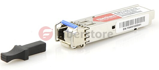
The optical transceiver is a self-contained component that transmits and receives signals. Usually, it is inserted in devices such as routers or network interface cards which provide one or more transceiver module slot. The transmitter takes an electrical input and converts it to an optical output from a laser diode or LED. The light from the transmitter is coupled into the fiber with a connector and is transmitted through the fiber optic cable plant. Then the light from the end of the fiber is coupled to a receiver where a detector converts the light into an electrical signal which is then conditioned properly for use by the receiving equipment. There are a full range of optical transceivers available in telecommunication market, like SFP transceiver, SFP+ transceiver (eg. SFP-10G-SR shown below), 40G QSFP+, 100G CFP, etc.SFP-10G-SR optical transceiver

Optical Transceiver Designing Considerations

It’s true that fiber links can handle higher data rates over longer distances than copper solutions, which drive the even wider use of optical transceivers. While designing fiber optic transceivers, the following aspects should be taken into consideration.

  • Environmental Situation

One challenge comes to the outside weather—especially severe weather at elevated or exposed heights. The components must operate over extreme environmental conditions, over a wider temperature range. The second environmental issue related to the optical transceiver design is the host board environment which contains the system power dissipation and thermal dissipation characteristics.

A major advantage of the fiber optic transceiver is the relatively low electrical power requirements. However, this low power does not exactly mean that the thermal design can be ignored when assembling a host configuration. Sufficient ventilation or airflow should be included to help dissipate thermal energy that is drawn off the module. Part of this requirement is addressed by the standardized SFP cage which is mounted on the host board and also serves as a conduit for thermal energy. Case temperature reported by the Digital Monitor Interface (DMI), when the host operates at its maximum design temperature, is the ultimate test of the effectiveness of the overall system thermal design.

  • Electrical Condition

Essentially, the fiber transceiver is an electrical device. In order to maintain error free performance for the data passing through the module, the power supply to the module must be stable and noise-free. What’s more, the power supply driving the transceiver must be appropriately filtered. The typical filters have been specified in the Multisource Agreements (MSAs) which have guided the original designs for these transceivers. One such design in the SFF-8431 specification is shown below.

filter

  • Optical Performance

Optical performance is measured as Bit Error Rate, or BER. The problem facing designing optical transceiver lie in the case that the optical parameters for the transmitter and receiver have to be controlled, so that any possible degradation of the optical signal while traveling along the fibers will not cause poor BER performance. The primary parameter of relevance is the BER of the complete link. That is, the start of the link is the source of the electrical signals which drive the transmitter, and at the end, the electrical signal is received and interpreted by the circuitry in the host by the receiver. For those communication links which use optical transceivers, the primary goal is to guarantee BER performance at different link distances, and to ensure broad interoperability with third party transceivers from different vendors.

Conclusion

Fiber technology is becoming maturer, leading to the wider use of optical transceivers. With the three aspects mentioned above in mind, designing fiber optic transceivers should be easier. FS.COM supplies many transceivers which are fully compatible with major brands, including HP compatible transceivers (eg. J4858C).

BiDi Transceiver Overview

For several years ago, when talked about fiber optic transceiver, almost most of people engaged in telecommunication industry would tell that a transceiver is a device comprising both a transmitter and a receiver which are combined and share common circuitry. Almost all fiber optic transceivers uses two fibers to transmit data between routers and switches. One fiber is devoted to transmitting data to the networking equipment, while the other one is devoted to receiving data from the networking equipment. For recent years, a new kind of fiber optic transceiver has been available — Bi-Directional transceiver (BiDi transceiver).

BiDi Transceiver Basis

BiDi transceiver is a type of fiber optic transceiver which uses WDM (wavelength division multiplexing) bi-directional transmission technology so that it can achieve the transmission of optical channels on a fiber propagating simultaneously in both directions. BiDi transceiver is only with one port which uses an integral bidirectional coupler to transmit and receive signals over a single optical fiber (see the following picture). BiDi transceivers are specifically designed for the high-performance integrated duplex data link over a single optical fiber and used in bi-directional communication applications. The BiDi transceivers interface a network device mother board (for a switch, router or similar device) to a fiber optic or unshielded twisted pair networking cable.

BiDi transceiver

Working Principle of BiDi Transceiver

The difference between BiDi transceivers and the two-fiber optical transceiver mainly lies in that BiDi transceivers are fitted with WDM couplers, also known as diplexers, which help to combine and separate data transmitted over a single fiber based on the wavelengths of the light. So BiDi transceivers are also called WDM transceivers. BiDi transceivers are usually deployed in matched pairs to get the work most efficiently. And the diplexers of BiDi transceivers are tuned to match the expected wavelength of the transmitter and receiver that they will be transmitting data from or to.

As can be seen from the following diagram, the paired BiDi transceivers are being used to connect two devices. Device A is used to get upstream data, and Device B is used to get downstream data. Tx means transmit. Rx means receive. The diplexer in one transceiver (Device A) should have a transmitting wavelength of 1310 nm and have a receiving wavelength of 1550 nm. The diplexer in the other transceiver (Device B) should have a transmitting wavelength of 1550 nm and have a receiving wavelength of 1310 nm.

BiDi transceiver

Advantages of BiDi Transceiver

The decisive advantage of using BiDi transceiver is that it helps to reduce the cost of fiber cabling infrastructure. This is caused by reducing the number of fiber path panel ports as well as reducing the amount of tray space dedicated to fiber management. The deployment of BiDi transceiver enables the bandwidth capacity of the optical fiber to be doubled.

FS.COM BiDi Transceiver Solution

FS.COM supplies a series of BiDi transceivers with different types such as BiDi SFP. These BiDi Gigabit SFP transceivers support Fast Ethernet, Gigabit Ethernet, and Fibre Channel, etc. And they can be available for simplex SC or LC connector interface, which is used for data transmitting and receiving. Also, the BiDi SFPs are able to support a wide range of physical media from copper to long-wave single-mode optical fiber with transmission distance up to hundreds of kilometers. The most typical Tx and Rx wavelength combinations are 1310/1490 nm, 1310/1550 nm and 1490/1550 nm. FS.COM has a large selection of BiDi transceivers in stock. Choosing a FS.COM BiDi transceiver can help your fiber optic network to be most economical and efficient.

Related Article: A Brief Introduction of BiDi SFP Transceiver

A New Age for Fiber Optic Transceiver

For transceivers, an optical interoperation with the associated circuitry is the key to success of application. Copper transceiver and fiber optic transceiver, as the two leading transceiver modules for data transmission, have their own unique benefits and drawbacks. This article has a brief comparison between copper transceiver and fiber optic transceiver, then explain why fiber optic transceiver is more preferable than copper transceiver.

Copper Transceiver vs Fiber Optic Transceiver

Copper is the de-facto standard for transmitting data between devices due to its low cost, easy installation and flexibility. Certainly, it possesses distinct defects too. Copper transceiver is best when applied in short length. Typically copper transceiver supports transmission distances of up to 100 meters or less. When employed over long distances, the electromagnetic signal characteristics will hinder performance.

On the other hand, fiber optic transceiver is often used for remote campus connectivity, crowded wiring closets, long-distance communications and environments that need protection from interference, such as manufacturing areas. It is extremely reliable and less susceptible to attenuation. Fiber optic transceiver supports multimode and single mode fiber optic cable types with transmission distances up to 120 kilometers. So fiber optic transceiver has a longer transmission distance than copper transceiver.

Fiber Optic Transceiver: A More Preferable Solution

Nowadays, more and more organizations choose to utilize fiber optic transceiver as it offers greater advantages than the conventional copper transceiver.

fiber optic transceiver

Firstly, fiber optic is made of glass, so it does not conduct electricity. And it is immune to electromagnetic interruption and lightning. Copper cable will produce electromagnetic currents that can interfere network if not properly installed. So fiber optic transceiver has more interference resistance than copper transceiver.

Secondly, fiber optic is generally free from corrosion as it is made of glass and not water or chemically sensitive. Thus it has no risk of being destroyed by any harsh elements. Also it can bear the living conditions that conventional copper cable fail to do, such as direct contact with the soil. Moreover, fiber optic is of small size and weight, for the same transmission capacity, copper cable requires more lines than fiber optic. The reduced number of lines allows for maximum space utilization. Thus for fiber optic transceiver, the maintenance and service expenses are much lower than the copper transceiver.

Thirdly, fiber optic can make the transmission of data with greater flexibility due to its unlimited bandwidth. It can support the increased information carrying capacity. The practical bandwidth far exceeds that of copper cable. Using fiber optic transceiver helps to minimize attenuation in your system. As a result, fiber optic transceiver provides greater data safety and efficiency.

As stated above, fiber optic transceiver is more preferable than copper transceiver. And it has been lauded as an innovation that would push broadband speeds forward. Hence, it is widely employed by more and more organizations. Fiberstore offers large kinds of high quality fiber optic transceiver at very low price. It’s a primary option for you.

Optimistic about the Development of 40G and 100G Network Devices in the Future

In June of 2010, the IEEE 802.3 ba 40G/100G standard issued. The Standard Approval timeline for IEEE 802.3ba is depicted in the figure. It makes me looking good forward to its development in the future. Traditional 10G port modules usually adopt LC connector, they are connected by dual cores while 40G Ethernet specification requires 8 cores connections, just 4 cores used for transmitting and another 4 cores used for receiving. Better advice for 40G Ethernet is that the 12 cores fiber cabling solution, each channel has 4 special transmitting fiber and 4 special receiving fiber, middle 4 fibers remain free. 100G Ethernet solution requires to make 24 fibers, it divided into two 12 fibers, one for receiving and another for transmitting, and each of the array, middle 10 fibers used for transit traffic, the two fibers on the ends are setting free.

Several years ago, once we met customers who wants to know if our transceiver modules support 40G and 100G ports, we will tell them that some suppliers who launched the 40G and 100G optical transceiver module are mostly based on previous 40G/100G draft, they are not the standard ports, and different vendors exist connection trouble, so we are all not sure. But nowadays, with the mature development of 40G and 100G cores, many supplier launched them their own fiber optic transceiver. In the field of 40G and 100G, device manufacturers adopt the advantage of long term evolution and 40G network which focus on 100G network communication equipment. In fact, it is the estimated results that operator who faces with 40G and 100G network. In the next year, 40G long distance transmission network market supplier will launch the 100G network transmission devices, it will bring a big challenge to the operator. The fact dedicates that fiber optic device operators will do double budgets for current production to meet the demand of the future developments.

In the network market, WDM devices are quite popular between global operators. It makes the sales of the products to improve highly. Adjustable and pluggable optical transceiver module, such as XFP, become quite popular in the ROADM network market, it will broaden the network scopes of operators, includes IP/Ethernet CMTs, OLTs FTTH, DSLAMs. As for the 10G SFP+ transceiver module, such as 10G SFP+ 1550nm 80km, it sales reached three times, they are primarily applied into 10G Ethernet and 8G/16G fiber channel. The main reason why development speed of 100G fiber network faster than 40G is that the price of 100G network is lower than 40G, so the much lower LR4 modules will have a great future. Related product: SFP-10G-LR, see at the figure.

Faced with the rapid progress of 40G and 100G optical transceiver modules, FS.COM also research its brand. Including production and sales of 40G and 100G. FS.COM has high quality and reasonable price. Our fiber optical transceivers all pass certification. If you have fiber optical transceivers needs, FS.COM will be your first choice.

What Is Inside of a Fiber Optic Cable

Fiber optic cable is unlike most types of cables; it draw on light instead of electricty to transmit signals. As you have already known, the light is the fasterst way to transfer information, and fiber optic cable has additional advantages are immune to electrical interference. So, you can run it anywhere and at any time. Because light meets litter or no resistance, you can run the fiber optic cable in a long distance, literally countries apart, without increasing or clean signal. Imagination process thousands of miles away. It will be impossible.

Optical fiber velocity also has its own advantages. It has a cleaner signal than conventional copper wire and transmit signals over 10 gb/s. Put it into perspective, fiber optic wiring is digital information as an electrical wiring is analog information. They are completely different.

At present, the fiber optic cable used to connect to the network, basically make the short run, the connection layer, construction and connection electric copper cable, fiber optic cable through the Ethernet converters. Despite the fiber optic cable can be very expensive, but because it is becoming more and more popular, it will be, the price of fiber optic cable (and related equipment including Ethernet converter and fiber optic transceiver) should be reduced.

Knowing what’s inside this very functional invention is good to know. A fiber optic cable including the core, cladding, strength member, buffer and jacket as its components. Let’s get to know them more!

Core cable to the path of the transmitted light can flow, by one or more of the glass or plastic fiber. The cladding which provides a refractor light beam reflected back to the core, to continue its journey is usually made of plastic. The buffer consists of one or more layers of plastic and strengthens the cable and prevents damage to the core. As the same implies, the strength members very hard materials, such as glass fiber, steel or kevlar, and provides additional strength for the cable. Finally, the jacket which can either be plenum or non plenum is the outer convering or shield of the cable.

Fiber optic cable comes in two forms: single mode and multi mode. Because single mode cable is so narrow, light can only travel through it in a single path. This cable is very expensive and is hard to work with. Multi mode cable, on the other hand, there are a wide range of core diameter of the optical flow of the freedom to travel several paths. Unfortunately, the multipath configuration multimode optical fiber allows the possibility of signal distortion at the receiving end.

Sometime in your connection, you will come across connecting either a single mode or multi mode fiber optic cable to conventional copper cable. This can be a problem which can cut the communication you have already established. But you don’t have to worry as there are Ethernet converters and transceiver modules that serve to router, boost, and deliver the signals across these two opposite cables. On top of these, there are other related devices such as gigabit converters and SFP mini GBICs readily available on the market that you might find useful in your network.

Source: fiberstore

The Data Center Infrastructure of 40G and 100G

Once the server upgrade, top of rack switch uplink require a higher speed. However, during the transition from 1G to 10G full of frustrations. In the past, server vendors comes 1GbE RJ-45 LAN-on-motherboard is free of charge. But now a dual-port 10GBASE-T expensive. Cat5e is almost free, Interconnect never in the past is not a serious cost problem, and now it is. The server companies sale 10G ports, can be mounted on pluggable “daughter card”, cut off the posterior of the subsequent market competitiors and monopoly high prices. Daughter card can and 1G 10GBASE-T, 2-4 SFP+ port and dual-port QSFP combination. With 100G CXP and CFP /2 will be collocation is used. Due to server company in 10G/40G upgrades made a large sums of money, we will ask such a question: “server company will return to the LOM mode, buyers will not need to pay?” Our answer: Yes. But just before the transition to 40G! 10GBASE-T has a problem in high power consumption, size and cost, therefore, when the market of the 10GBASE-T in the development of 28-nm version, so that the SFP+ DAC take advantage. This makes the entire industry landscape has changed greatly. DAC also has its problems. Because it is electrically connected to two different systems, not all of the SFP+ port is the same.

The server-switch link update from 1G to 10G, and the switch uplink increased to 40G, TOR (Top of Rack) switch to connect to the EOR (End of Row) switch until the aggregation switching layer. Data center operators just the economic gloom stood up, still tight budget. “Incremental upgrade” is the investment strategy of the operators. Increase “necessary” 10G/40G link is the current investment. 100G seems to be the exhibition and media attention, but 40G is to make money in the next 2-3 years. Data center began to need 4 ~ 6g, not even to 10G. Therefore, many data center is still in excess, will need to upgrade “. Google, Facebook, Microsoft and other so-called $ 1 billion super data center so that people stare, but they do not represent the mainstream of the data center.

To chase fiber transceiver opportunities, multiple transceiver suppliers is the first to provide less than 50 meters transmission distance of 40G QSFP SR transceiver and Ethernet AOC. 40G QSFP MSA blessed with multi-mode fiber can support short-range (SR) – 100 meters, with the dual-core single-mode fiber with 10km-all in the same QSFP switch port can support. QSFP can plug 36-44 ports per line card, while the CFP can only be inserted 2 in 32W. Although it is very popular in the telecommunications, but not in data communication! OEM prices ranging from $2000 to $3000, it depending on the needs of the data center or telecommunications.

The urgent need for the data center to support tens of thousands of 100G medium transmission link length from the information explosion in demand. Industry conference clamoring. These flow requirements from server virtualization, big data, smart phones, tablet PCs and even software defined network (SDN). Large core switch companies mainly 10-Channel CXP for multi-mode, working together with the transceiver and the AOC. In 4x25G the 25G transmission, multi-mode noise spikes may pose a threat to the multimode transceiver down to 25-50 meters FEC and / or equalization may be required to reach 125 meters. This will make 25-125 meters away from the transceiver higher prices. With 2km Single mode Fiber Optic Transceiverprices narrowed.

At present, the transmission distance of 100m – 600m, there is no economically feasible 100G solutions (unless it can be described with two 40G and 10G transceivers). When the data center becomes greater, which is a hot spot, the IEEE focus of debate. Each additional add 1m, causes the transceiver OEM Price from CXP $ 1,000 he went to the telecentres CFP $ 16,000! Usually claimed transmission 2 km, in fact, can only transmit 400-600 meters, in a loss of data center environments, patch panel and dirty connector can only get 4-5 dB, 10 km link you need to 6dB. Next-generation lasers and instead of SiGe CMOS electronic devices are being developed, but, CMOS electronic harder to develop.

The 40G and 100G are two main data center “form”. Short-range transceiver (SR4), the use of multimode optical fiber can transmit about 100 meters. Using single-mode fiber can transmit 100 meters to 10 kilometers long range transceiver (LR4). This so-called, no formal terminology NR4 aspirations 2km 4dB. SR transceivers typically used to connect a computer cluster and switch layer in the data center. SR transceiver and OM4 fiber combination, can transmit about 300 meters. 125-200 meters, the conversion using single-mode fiber, transceivers and fiber can bring benefit return; even in 25G transmission, also can bring benefits.

The 40G usually in the QSFP or QSFP MSA, usually in four of the 10G channels laying. SR transceiver uses eight multimode fiber (corresponding to one direction), VCSEL lasers and QSFP MSA. LR transceiver uses edge-emitting lasers, multiplex four 10G channels to two single-mode fiber, the single-mode fiber in the transmission of the CFP module MSA 10km, soon also be reached in 28 CFP / 2 and QSFP MSA on this distance. 40G, SR4 and LR4 can be used for the same QSFP switch interface, no problem – just plug in, you can run – you can reach one meter -10 km without any problems. (But still does not work in the 100G)

The 100G SR10 use 20 multimode fiber, VCSELs and CXP MSA. 100G LR4 CFP and two single-mode fiber. Though he promised transmission 100 meters, but the SR10 CXP transceiver typically used to connect large-scale aggregation and core switches from less than 50 meters, when the distance becomes longer, the more than 20-mode fiber will be very expensive, because the multi-mode the optical fiber is about 3 times more expensive than the single-mode fiber. Only in 2012, a number of transceiver companies have announced the development of the CXP 100G SR transceiver. The the 40G QSFP transceiver and the AOCs since 2008 come out. Later on, 4x25G QSFP SR transceiver may to appear CXP transceiver market 10x10G.

Source: fiberstore.com