To address the efficiency challenges of rapidly growing data storage and retrieval within data centers, the use of Ethernet-converged distributed storage networks is becoming increasingly popular. However, in storage networks where data flows are mainly characterized by large flows, packet loss caused by congestion will reduce data transmission efficiency and aggravate congestion. In order to solve this series of problems, RDMA technology emerged as the times require.
What is RDMA?
RDMA (Remote Direct Memory Access) is an advanced technology designed to reduce the latency associated with server-side data processing during network transfers. Allowing user-level applications to directly read from and write to remote memory without involving the CPU in multiple memory copies, RDMA bypasses the kernel and writes data directly to the network card. This achieves high throughput, ultra-low latency, and minimal CPU overhead. Presently, RDMA’s transport protocol over Ethernet is RoCEv2 (RDMA over Converged Ethernet v2). RoCEv2, a connectionless protocol based on UDP (User Datagram Protocol), is faster and consumes fewer CPU resources compared to the connection-oriented TCP (Transmission Control Protocol).
Building Lossless Network with RDMA
The RDMA networks achieve lossless transmission through the deployment of PFC and ECN functionalities. PFC technology controls RDMA-specific queue traffic on the link, applying backpressure to upstream devices during congestion at the switch’s ingress port. With ECN technology, end-to-end congestion control is achieved by marking packets during congestion at the egress port, prompting the sending end to reduce its transmission rate.
Optimal network performance is achieved by adjusting buffer thresholds for ECN and PFC, ensuring faster triggering of ECN than PFC. This allows the network to maintain full-speed data forwarding while actively reducing the server’s transmission rate to address congestion.
Accelerating Cluster Performance with GPU Direct-RDMA
The traditional TCP network heavily relies on CPU processing for packet management, often struggling to fully utilize available bandwidth. Therefore, in AI environments, RDMA has become an indispensable network transfer technology, particularly during large-scale cluster training. It surpasses high-performance network transfers in user space data stored in CPU memory and contributes to GPU transfers within GPU clusters across multiple servers. And the Direct-RDMA technology is a key component in optimizing HPC/AI performance, and NVIDIA enhances the performance of GPU clusters by supporting the function of GPU Direct-RDMA.
Streamlining RDMA Product Selection
In building high-performance RDMA networks, essential elements like RDMA adapters and powerful servers are necessary, but success also hinges on critical components such as high-speed optical modules, switches, and optical cables. As a leading provider of high-speed data transmission solutions, FS offers a diverse range of top-quality products, including high-performance switches, 200/400/800G optical modules, smart network cards, and more. These are precisely designed to meet the stringent requirements of low-latency and high-speed data transmission.
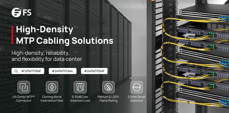
In the era of ultra-high-speed data transmission, MTP/MPO cables have become a key player, especially in the context of 800G networks. In essence, MTP/MPO cables emerge as catalysts for the evolution toward 800G networks, offering a harmonious blend of high-density connectivity, reliability, and scalability. This article will delve into the advantages of MTP/MPO cables in 800G networks and provide specific solutions for constructing an 800G network, offering valuable insights for upgrading your existing data center.
Challenges Faced in 800G Data Transmission
As a critical hub for storing and processing vast amounts of data, data centers require high-speed and stable networks to support data transmission and processing. The 800G network achieves a data transfer rate of 800 Gigabits per second (Gbps) and can meet the demands of large-scale data transmission and processing in data centers, enhancing overall efficiency.
Therefore, many major internet companies are either constructing new 800G data centers or upgrading existing data centers from 100G, 400G to 800G speeds. However, the pursuit of 800G data transmission faces numerous complex challenges that necessitate innovative solutions. Here, we analyze the intricate obstacles associated with achieving ultra-fast data transmission.
Insufficient Bandwidth & High Latency
The 800G network demands extensive data transmission, placing higher requirements on bandwidth. It necessitates network equipment capable of supporting greater data throughput, particularly in terms of connection cables. Ordinary optical fibers typically consist of a single fiber within a cable, and their optical and physical characteristics are inadequate for handling massive data, failing to meet the high-bandwidth requirements of 800G.
While emphasizing high bandwidth, data center networks also require low latency to meet end-user experience standards. In high-speed networks, ordinary optical fibers undergo more refraction and scattering, resulting in additional time delays during signal transmission.
Limited Spatial Layout
The high bandwidth requirements of 800G networks typically come with more connection ports and optical fibers. However, the limited space in data centers or server rooms poses a challenge. Achieving high-density connections requires accommodating more connection devices in the constrained space, leading to crowded layouts and increased challenges in space management and design.
Complex Network Architecture
The transition to an 800G network necessitates a reassessment of network architecture. Upgrading to higher data rates requires consideration of network design, scalability, and compatibility with existing infrastructure. Therefore, the cabling system must meet both current usage requirements and align with future development trends. Given the long usage lifecycle of cabling systems, addressing how to match the cabling installation with multiple IT equipment update cycles becomes a challenging problem.
High Construction Cost
Implementing 800G data transmission involves investments in infrastructure and equipment. Achieving higher data rates requires upgrading and replacing existing network equipment and cabling management patterns, incurring significant costs. Cables, in particular, carry various network devices, and their required lifecycle is longer than that of network equipment. Frequent replacements can result in resource wastage.
Effectively addressing these challenges is crucial to unlocking the full potential of a super-fast, efficient data network.
The significance of MTP/MPO cables in high-speed networks, especially in 800G networks, lies in their ability to manage the escalating data traffic efficiently. The following are key advantages of MTP/MPO cables:
High Density, High Bandwidth
MTP/MPO cables adopt a high-density multi-fiber design, enabling the transmission of multiple fibers within a relatively small connector. This design not only provides ample bandwidth support for data centers, meeting the high bandwidth requirements of an 800G network, but also helps save space and supports the high-density connection needs for large-scale data transfers.
Additionally, MTP/MPO cables exhibit excellent optical and mechanical performance, resulting in low insertion loss in high-speed network environments. By utilizing a low-loss cabling solution, they effectively contribute to reducing latency in the network.
Flexibility and Scalability
MTP/MPO connectors come in various configurations, accommodating different fiber counts (8-core, 12-core, 16-core, 24-core, etc.), supporting both multimode and single-mode fibers. With trunk and breakout designs, support for different polarities, and male/female connector options, these features allow seamless integration into various network architectures. The flexibility and scalability of MTP/MPO connectors enable them to adapt to evolving network requirements and facilitate future expansions, particularly in the context of 800G networks.
Efficient Maintenance
The high-density and compact design of MTP/MPO cables contribute to saving rack and data room space, enabling data centers to utilize limited space resources more efficiently. This, in turn, facilitates the straightforward deployment and reliable operation of 800G networks, reducing the risks associated with infrastructure changes or additions in terms of cost and performance. Additionally, MTP/MPO cables featuring a Plenum (OFNP) outer sheath exhibit fire resistance and low smoke characteristics, minimizing potential damage and saving on cabling costs.
Scaling the 800G Networks With MTP/MPO Cables
In the implementation of 800G data transmission, the wiring solution is crucial. MTP/MPO cables, as a key component, provide reliable support for high-speed data transmission. FS provides professional solutions for large-scale data center users who require a comprehensive upgrade to 800G speeds. Aim to rapidly increase data center network bandwidth to meet the growing demands of business.
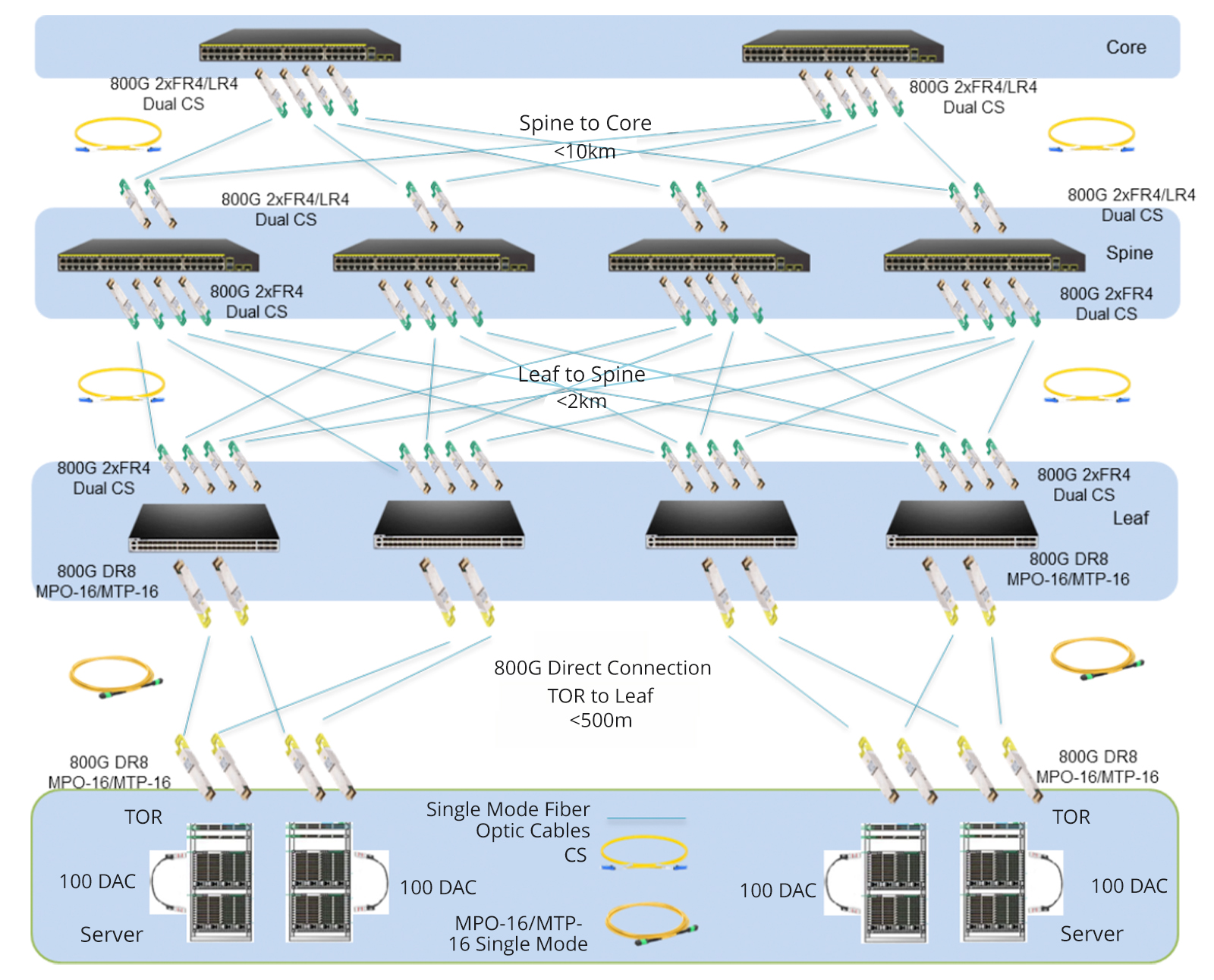
Newly Built 800G Data Center
Given the rapid expansion of business, many large-scale internet companies choose to build new 800G data centers to enhance their network bandwidth. In these data centers, all network equipment utilizes 800G switches, combined with MTP/MPO cables to achieve a direct-connected 800G network. To ensure high-speed data transmission, advanced 800G 2xFR4/2xLR4 modules are employed between the core switches and backbone switches, and 800G DR8 modules seamlessly interconnect leaf switches with TOR switches.
To simplify connections, a strategic deployment of the 16-core MTP/MPO OS2 trunk cables directly connects to 800G optical modules. This strategic approach maximally conserves fiber resources, optimizes wiring space, and facilitates cable management, providing a more efficient and cost-effective cabling solution for the infrastructure of 800G networks.
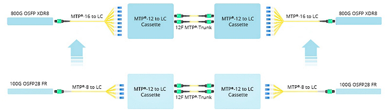
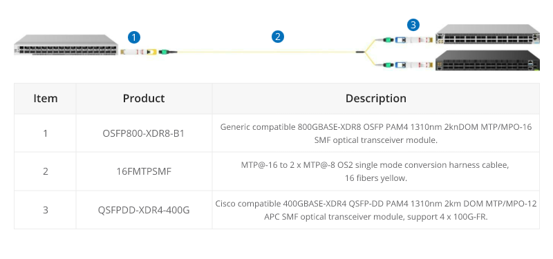
Upgrade from 100G to 800G
Certainly, many businesses choose to renovate and upgrade their existing data center networks. In the scenario below, engineers replaced the original 8-core MTP/MPO-LC breakout cable with the 16-core version, connecting it to the existing MTP cassettes. The modules on both ends, previously 100G QSFP28 FR, were upgraded to 800G OSFP XDR8. This seamless deployment migrated the existing structured cabling to an 800G rate. It is primarily due to the 16-core MTP/MPO-LC breakout cable, proven as the optimal choice for direct connections from 800G OSFP XDR8 to 100G QSFP28 FR or from 800G QSFP-DD/OSFP DR8 to 100G QSFP28 DR.
In short, this solution aims to increase the density of fiber optic connections in the data center and optimize cabling space. Not only improves current network performance but also takes into account future network expansion.
Elevating from 400G to the 800G Network
How to upgrade an existing 400G network to 800G in data centres? Let’s explore the best practices through MTP/MPO cables to achieve this goal.
Based on the original 400G network, the core, backbone, and leaf switches have all been upgraded to an 800G rate, while the TOR (Top of Rack) remains at a 400G rate. The core and backbone switches utilise 800G 2xFR4/2xLR4 modules, the leaf switches use 800G DR8 modules, and the TOR adopts 400G DR4 modules. Deploying two 12-core MTP/MPO OS2 trunk cables in a breakout configuration between the 400G and 800G optical modules facilitates interconnection.
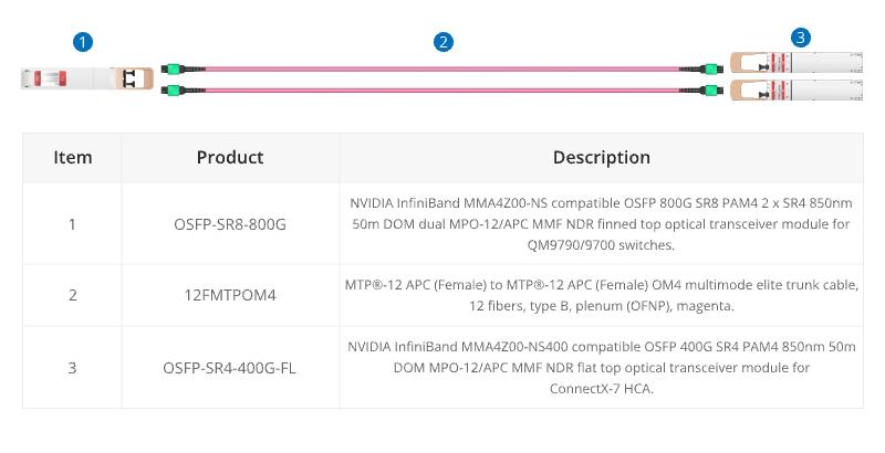
Furthermore, there is a second connectivity option where the 800G port optical module utilises OSFP SR8, the 400G port uses OSFP SR4 optical module, and the intermediate cables are connected using 12-core MTP® OM4 trunk cables.
These two cabling solutions enhance scalability, prevent network bottlenecks, reduce latency, and are conducive to expanding bandwidth when transitioning from lower-speed to higher-speed networks in the future. Additionally, this deployment retains the existing network equipment, significantly lowering cost expenditures.
Ultimately, the diverse range of MTP/MPO cable types provides tailored solutions for different connectivity scenarios in 800G networks. As organizations navigate the complexities of high-speed data transmission, MTP/MPO cables stand as indispensable enablers, paving the way for a new era of efficient and robust network infrastructures.
How FS Can Help
The comprehensive networking solutions and product offerings not only save costs but also reduce power consumption, delivering higher value. Considering an upgrade to 800G for your data center network? FS tailors customized solutions for you. Don’t wait any longer—Register as an FS website member now and enjoy free technical support.
Choosing the right MTP/MPO cable ensures efficient and reliable data transmission in today’s fast-paced digital world. With the increasing demand for high-speed connectivity, it is essential to understand the importance of core numbers in MTP/MPO cables. In this guide, we will explore the significance of core numbers and provide valuable insights to help you decide when selecting the right MTP/MPO cable for your specific needs. Whether setting up a data center or upgrading your existing network infrastructure, this article will serve as a comprehensive resource to assist you in choosing the right MTP/MPO cable.
What is an MTP/MPO cable
An MTP/MPO cable is a high-density fiber optic cable that is commonly used in data centers and telecommunications networks. It is designed to provide a quick and efficient way to connect multiple fibers in a single connector.
MPO and MTP cables have many attributes in common, which is why both are so popular. The key defining characteristic is that these cables have pre-terminated fibers with standardized connectors. While other fiber optic cables have to be painstakingly arrayed and installed at each node in a data center, these cables are practically plug-and-play. To have that convenience while still providing the highest levels of performance makes them a top choice for many data center applications.
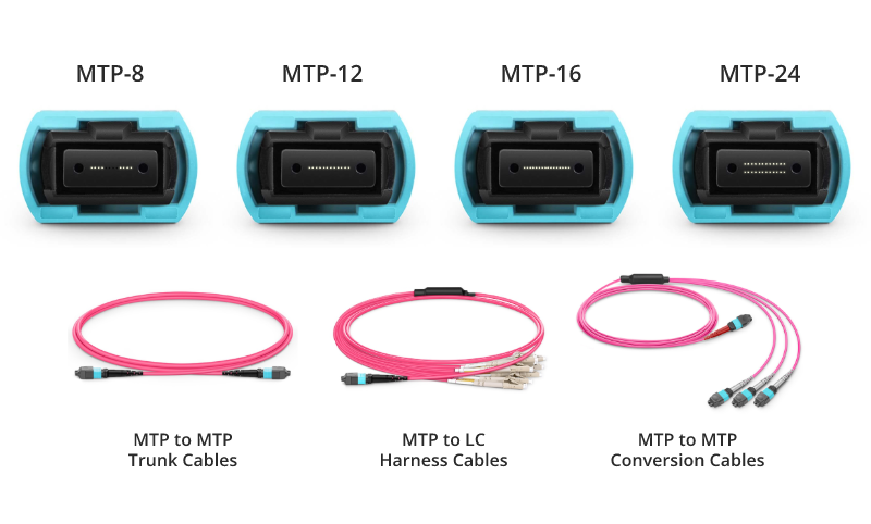
MTP/MPO trunk cables, typically used for creating backbone and horizontal interconnections, have an MTP/MPO connector on both ends and are available from 8 fibers up to 48 in one cable.
MTP/MPO Harness/Breakout Cables
Harness/Breakout cables are used to break out the MTP/MPO connector into individual connectors, allowing for easy connection to equipment. MTP/MPO conversion cables are used to convert between different connector types, such as MTP to LC or MTP to SC.
The MTP/MPO cables also come in different configurations, such as 8-core, 12-core, 16-core, 32-core, and more, depending on the specific needs of the application. This flexibility in configurations enables users to tailor their choices according to the scale and performance requirements of their networks or data centers. As technology advances, the configurations of MTP/MPO cables continually evolve to meet the increasing demands of data transmission.
How to Choose MTP/MPO cables
Selecting the appropriate core number for MTP/MPO cables resonates throughout the efficiency and performance of networks. In this section, we’ll delve into the decision-making factors surrounding core numbers in cables.
Network Requirements and Data Transmission Goals
Different network applications and data transmission needs may require varying numbers of cores. High-density data centers might necessitate more cores to support large-capacity data transmission, while smaller networks may require fewer cores.
Compatibility with Existing Infrastructure
When choosing the core number for MTP/MPO cables, compatibility with existing infrastructure is crucial. Ensuring that the new cables match existing fiber optic equipment and connectors helps avoid unnecessary compatibility issues.
Consideration for Future Scalability
As businesses grow and technology advances, future network demands may increase. Choosing MTP/MPO cables with a larger number of cores allows for future expansion and upgrades.
Budget and Resource Constraints
Budget and resources also play a role in core number selection. Cables with a larger number of cores tend to be more expensive, while cables with fewer cores may be more cost-effective. Therefore, finding a balance between actual requirements and the available budget is essential.
MTP/MPO Cabling Guide to Core Numbers
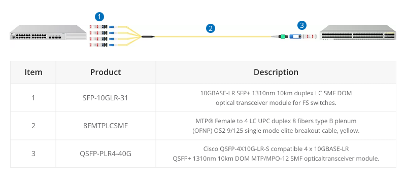
40G MTP/MPO Cabling
A 12-fiber MTP/MPO connector interface can accommodate 40G, which is usually used in a 40G data center. The typical implementations of MTP/MPO plug-and-play systems split a 12-fiber trunk into six channels that run up to 10 Gigabit Ethernet (depending on the length of the cable). 40G system uses a 12-fiber trunk to create a Tx/Rx link, dedicating 4 fibers for 10G each of upstream transmit, and 4 fibers for 10G each of downstream receive.
40G-10G Connection
In this scenario, a 40G QSFP+ port on the FS S5850 48S6Q switch is split up into 4 10G channels. An 8-fiber MTP-LC harness cable connects the 40G side with its MTP connector and the four LC connectors link with the 10G side.
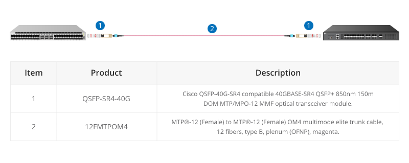
40G-40G Connection
As shown below, a 12-fiber MTP trunk cable is used to connect two 40G optical transceivers to realize the 40G to 40G connection between the two switches. The connection method can also be applied to a 100G-100G connection.
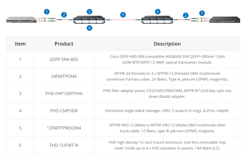
40G Trunk Cabling
24 Fibers MTP® to MTP® Interconnect Conversion Harness Cable is designed to provide a more flexible multi-fiber cabling system based on MTP® products. Unlike MTP® harness cable, MTP® conversion cables are terminated with MTP® connectors on both ends and can provide more possibilities for the existing 24-fiber cabling system. The 40/100G MTP® conversion cables eliminate the wasted fibers in the current 40G transmission and upcoming 100G transmission. Compared to purchasing and installing separate conversion cassettes, using MTP® conversion cables is a more cost-effective and lower-loss option.
100G MTP/MPO Cabling
QSFP28 100G transceivers using 4 fiber pairs have an MTP/MPO 12f port (with 4 unused fibers). Transmission for short distances (up to 100m) could be done most cost-effectively over multimode fiber using SR4 transmission. Longer distances over single mode use PSM4 transmission over 8 fibers. Transmission over 4 fiber pairs enables both multimode and single-mode transceivers to be connected 1:4 using MPO-LC 8 fiber breakout cables. One QSFP28 100G can connect to four SFP28 25G transceivers.
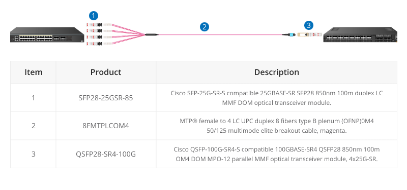
100G SR4 Parallel BASE-8 over Multimode Fibre
QSFP28 100G SR4 are often connected directly together due to their proximity within switching areas.
Equally QSFP28 SR4 are often connected directly to SFP28 25G ports within the same rack. For example, from a switch 100G port to four different servers with 25G ports.
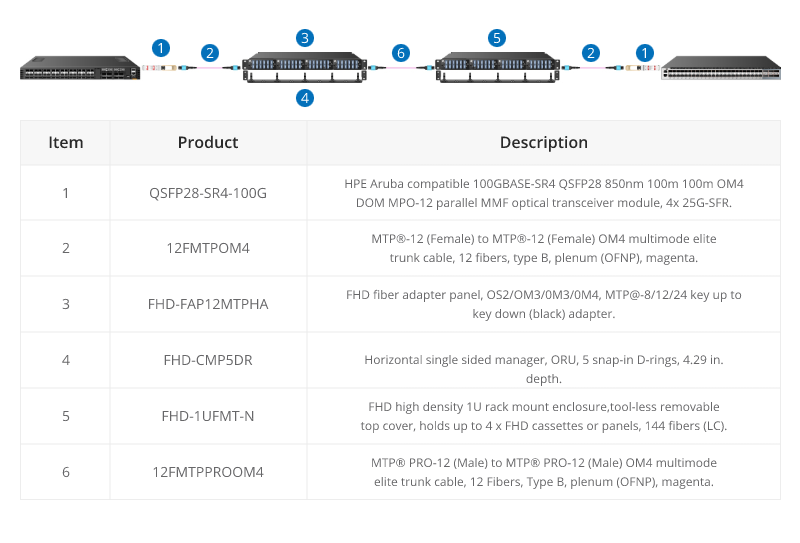
The 12-core MTP/MPO cables can also be used for 100G parallel to parallel connection. Through the use of MTP patch panels, network reliability is enhanced, ensuring the normal operation of other channels even if a particular channel experiences a failure. Additionally, by increasing the number of parallel channels, it can meet the continuously growing data demands. This flexibility is crucial for adapting to future network expansions.
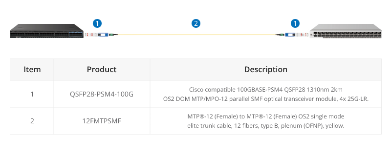
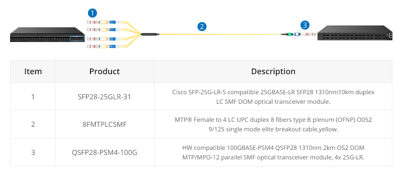
100G PMS4 Parallel BASE-8 over Singmode Fibre
QSFP28 100G PMS4 are often connected directly together due to their proximity within switching areas.
Equally QSFP28 ports are often connected directly to SFP28 25G ports within the same rack. For example, from a switch 100G port to four different servers with 25G ports.
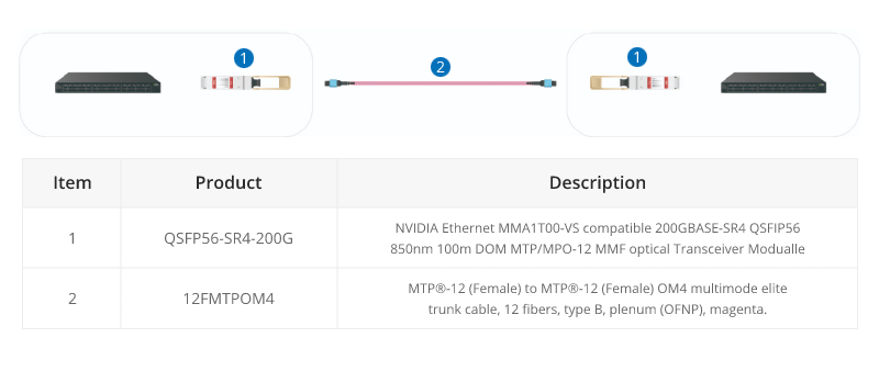
200G MTP/MPO Cabling
Although most equipment manufacturers (Cisco, Juniper, Arista, etc) are bypassing 200G and jumping from 100G to 400G, there are still some 200G QSFP-DD transceivers on the market, like FS QSFP56-SR4-200G and QSFP-FR4-200G.
200G-to-200G links
MTP (MPO) 12 fiber enables the connection of 2xQSFP56-SR4-200G to each other.
400G MTP/MPO Cabling
MTP/MPO cables with multi-core connectors are used for optical transceiver connection. There are 4 different types of application scenarios for 400G MTP/MPO cables. Common MTP/MPO patch cables include 8-fiber, 12-core, and 16-core. 8-core or 12-core MTP/MPO single-mode fiber patch cable is usually used to complete the direct connection of two 400G-DR4 optical transceivers. 16-core MTP/MPO fiber patch cable can be used to connect 400G-SR8 optical transceivers to 200G QSFP56 SR4 optical transceivers, and can also be used to connect 400G-8x50G to 400G-4x100G transceivers. The 8-core MTP to 4-core LC duplex fiber patch cable is used to connect the 400G-DR4 optical transceiver with a 100G-DR optical transceiver.
In the higher-speed 800G networking landscape, the high density, high bandwidth, and flexibility of MTP/MPO cables have played a crucial role. Leveraging various branching or direct connection schemes, MTP/MPO cables are seamlessly connected to 800G optical modules, 400G optical modules, and 100G optical modules, enhancing the richness and flexibility of network construction.
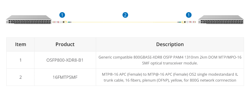
800G Connectivity with Direct Connect Cabling
16 Fibers MTP® trunk cable is designed for 800G QSFP-DD/OSFP DR8 and 800G OSFP XDR8 optics direct connection and supporting 800G transmission for Hyperscale Data Center.
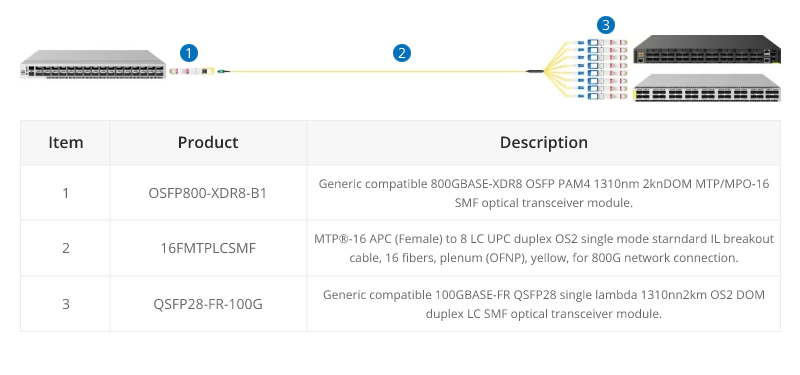
16 fibers MTP®-LC breakout cables are optimized for 800G OSFP XDR8 to 100G QSFP28 FR, 800G QSFP-DD/OSFP DR8 to 100G QSFP28 DR optics direct connection, and high-density data center applications.
800G to 2X400G Interconnect
16 fiber MTP® conversion cable is designed to provide a more flexible multi-fiber cabling system based on MTP® products. Compared to purchasing and installing separate conversion cassettes, using MTP® conversion cables is a more cost-effective and lower-loss option. In the network upgrade from 400G to 800G, the ability to directly connect an 800G optical module and two 400G optical modules provides a more efficient use of cabling space, resulting in cost savings for cabling.
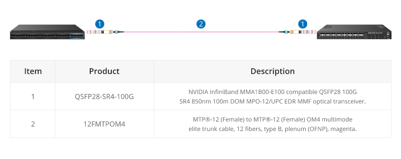
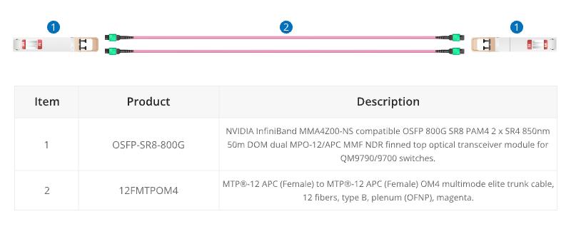
When using InfiniBand technology for networking purposes, 12 fibre MTP® trunk cable is designed for linking InfiniBand and Ethernet multimode twin-port OSFP and single-port OSFP and QSFP112 transceivers together.
Conclusion
In a word, the choice of core number for MTP/MPO cables depends on the specific requirements of the network application. Matching the core number with the requirements of each scenario ensures optimal performance and efficient resource utilization. A well-informed choice ensures that your MTP/MPO cable not only meets but exceeds the demands of your evolving connectivity requirements.
How FS Can Help
As a global leader in enterprise-level ICT solutions, FS not only offers a variety of MTP/MPO cables but also customizes exclusive MTP/MPO cabling solutions based on your requirements, helping your data center network achieve a smooth upgrade. In the era of rapid growth in network data, the time has come to make a choice – FS escorts your data center upgrade. Register as an FS website member and enjoy free technical support.
Budget is always the most direct choice factor when installing cables. Copper cable vs fibre optic cable price, it’s true that the popular impression is that copper is cheap, fibre is expensive. Well, at a certain period in the past decades, it’s true. However, today with the development of networking, is copper cabling really cheaper than fibre optic cabling?
Copper vs Fibre: What’s the Difference?
Copper and fibre optic cable are different cable types. Copper cable, also called RJ45 Ethernet cable, transmits data by electrical impulses, which is perfectly adequate for voice signals. Copper cables have many types such as Cat5, Cat6, Cat7 and Cat8, which can reach different transmission speeds. Cat5 Ethernet cable is once as slow as 10 Mbps over 100 metres. However, on today’s market, copper is getting faster. That the latest technology Cat8 Ethernet cable speed now can reach 40Gbps for 20 metres, but note that it has the notable limitation with regard to distance.
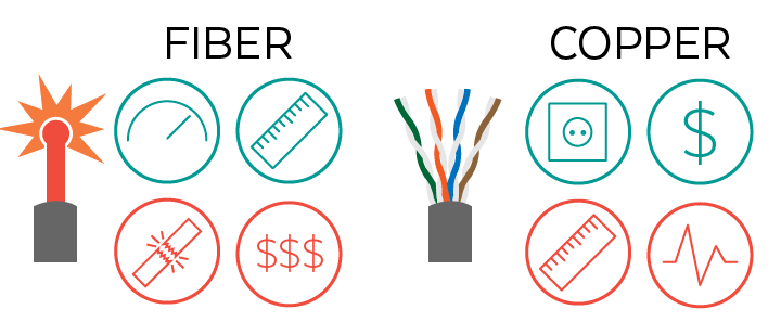
Unlike copper cable, fibre cable is made from fine hair-like glass fibres, which transmits data via light. Therefore, fibre cable does not conduct electricity, which is impervious to radio frequency interference. It’s naturally more durable than copper that it can withstand tougher environments and harsher weather conditions. As for the speed, fibre definitely wins for sheer speed and longer transmission distance. For example, the maximum distance of single mode fibre OS2 can be up to 200km. The following table makes a clear comparison between copper and fibre cables.
Fibre
Copper
Distance
Longer
Shorter
Speed
Faster
Fast
Durability
Lower
High
Spark Hazard
Hazardous
No spark hazard
Noise
Immune
Susceptible to EM/RFI interference, crosstalk and voltage surges
Factors of Copper Cable vs Fibre Optic Cable Price
People always believe the cost of fibre optic cables are expensive. Is it true? The following will discuss it in two main factors.
Installation Cost
Due to the technological differences between fibre and copper cables, their installation cost are different. Fibre’s immunity to electromagnetic interference (EMI) can save users’ cost, because they don’t need to lay fibre optic cables in the pipeline for avoiding electromagnetic interference. But copper cables need some protection, which increases the installation cost. Besides, in many scenarios, users need distributed cabinets for copper network while fibres don’t require this due to the longer distances. There are duplicated costs of building comms rooms, air con, ventilation, UPS (Uninterruptible Power Source) that people should not ignore in copper cabling. All these installation costs will exceed the extra cost of fibre equipment in a centralized fibre architecture. Therefore, if people decide to build a new data center, choosing fibre-based LAN is a much more economical solution than a copper networking environment.
Support Cost
Fibre optic cables are not fire hazard since light can not catch on fire. This means fibre cabling can save the cost of fire prevention. And fibre cables don’t break as easily, that customers will not worry about replacing them frequently. Thus, the support cost of fibre is less than the copper cable.
On the other hand, the increasing demand for fibre cables results in dropping prices. For example, at FS.COM, a Cat6 UTP cable with 3ft length needs 2.2 dollars, while LC to LC UPC duplex single mode fibre patch cable with 3ft length just costs 3 dollars. The price difference is narrow. Therefore, when copper cable vs fibre optic cable price, the cost of copper cabling is not much cheaper than fibres.
Conclusion
In conclusion, copper cable vs fibre optic cable price, the copper one is not always the cheapest choice. When building a new network, people should not ignore the installation and support costs of these different cabling solutions. It’s wise to choose one according to the actual installation environments. If you have any further questions about fibre or copper cabling, you can always get in touch with FS.COM staff via sales@fs.com.
SFP, RJ45, and GBIC transceiver modules are three main kinds of 1GbE transceiver modules on the market. You may be puzzled by so many choices of transceiver modules. Don’t worry about it. This article will help you clarify the differences among SFP vs RJ45 vs GBIC transceivers and give you some suggestions about how to choose from them.
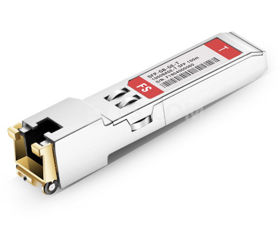
What Is an SFP Transceiver?
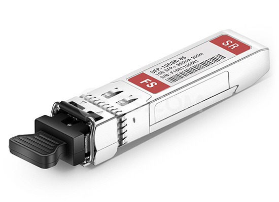
Short for small form-factor pluggable, an SFP module is a kind of fiber optic transceiver module with LC duplex interface. It supports the transmission data rate of 1GbE. SFP optical transceivers can operate on single mode or multimode fiber patch cables. The transmission distance of SFP modules ranges from 550m to 150km.
Figure1: SFP transceiver module
What Is an RJ45 Transceiver?
SFP copper RJ45 transceiver is a kind of transceiver with copper RJ45 interface. SFP copper RJ45 transceiver modules can support the transmission data rate of 1GbE. They are often used with Cat5 cables. SFP copper RJ45 transceivers are popular to be used for short distance transmission, because the overall cost of the copper network is lower compared with the optical network.
Figure2: SFP copper RJ45 transceiver module
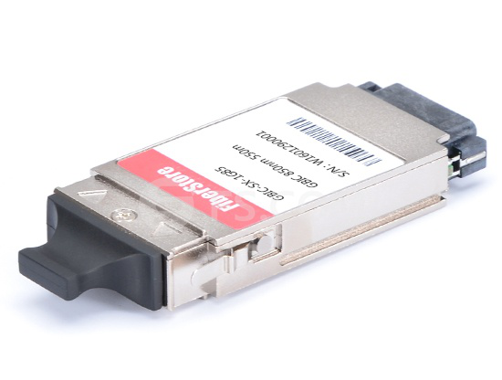
What Is a GBIC Transceiver?
Gigabit interface converter (GBIC), is a kind of hot pluggable fiber optic transceiver module. With the data rate of 1GbE, GBIC transceiver modules can transmit data through the distance of 550m to 80km. A GBIC module supports the same data rate with an SFP module, but a GBIC transceiver module has twice the size of an SFP transceiver module.
Figure3: GBIC transceiver module
SFP vs RJ45 vs GBIC: What’s the Difference?
After getting a general idea about what are SFP, RJ45, and GBIC transceivers, we will talk about the differences among them. The following chart shows the differences among SFP vs RJ45 vs GBIC transceiver modules from 4 aspects.
Transceiver module
SFP
SFP copper RJ45
GBIC
Interface
LC duplex
RJ45
SC duplex
Transmission distance
550m~150km
100m
550m~80km
Cable type
SMF/MMF
Cat 5
SMF/MMF
Data rate
1000Mbps
1000Mbps
1000Mbps
SFP vs RJ45 vs GBIC: When to Choose Which?
As is shown in the chart, SFP, SFP copper RJ45, and GBIC transceiver modules are all used in 1Gbit data transmission. Then when to choose which for the 1GbE network?
When to Choose SFP Transceivers?
Compared with GBIC transceiver modules, SFP modules have a smaller size. So SFP modules allow having more interfaces on a line card or a switch. Besides, SFP transceivers can support the transmission distance much longer than SFP copper RJ45 transceivers and GBIC transceivers. So if you require long transmission distance, SFP transceivers can meet your need. Last but not least, If you already have a line card or a switch with empty SFP slots, then you need to adapt to that.
When to Choose SFP Copper RJ45 Transceivers?
When your budget is not enough to use SFP transceivers, you can choose SFP copper RJ45 transceivers for short-distance transmission. If you have the requirement of long-distance transmission afterward, you can use SFP to RJ45 slot media converters. For they can provide an economical path to extend the distance of an existing network with fiber cabling.
When to Choose GBIC Transceivers?
If you already have a line card or a switch with unoccupied GBIC slots, then you need to choose GBIC transceivers to make full use of the empty slots on your switch. In fact, GBIC transceiver modules are gradually replaced by SFP modules on the market. For SFP transceivers are regarded as the upgraded version of GBIC modules.
Summary
The differences among SFP vs RJ45 vs GBIC transceiver modules include the interface type, transmission distance, and cable type. Your choice among them depends on different situations. If you want to buy Cisco SFP modules or other transceiver modules with high quality and low cost, please contact us at sales@fs.com.
The computer switch though has long existed in the market, few people can speak on it with great familiarity. As the network expands, the computer switch grows more sophisticated and diversified. This post sheds light on the computer switch from its definition, working principle and types.
What Is a Computer Switch?
A computer switch is an Ethernet switch in nature. It is a small hardware device that links multiple PCs, printers, assess points, phones, lights and servers together within one local area network, wide area network and different network topology. Each device connected to the switch is automatically connected to and can communicate with other connected devices, as the switch is essentially designed for information exchange. So if you hook up your cable modem to a router, then connect the router to a switch, all devices plugged into the switch can access the Internet, send and receive information and approach shared resources in a smooth, highly secure, and transparent manner.
How Does a Computer Switch Work?
The computer switch doesn’t exchange information randomly but follow the specific instructions—the MAC addresses of every device. The IP packet arrives at the correct destination with the aid of the frame using MAC addresses of destination and source. It is the computer switch that shoulders the responsibility to complete process as follows.
Learning – The switch learns the MAC address of the device on the switch port on which it receives the frame.
Forwarding – The switch forwards message in either unicast or broadcast way. That depends on whether the destination MAC is known for sure or unknown.
Filtering – The frame will be forwarded through that switch port only for which the switch has already learned the MAC address in its MAC table.
Common Types of Computer Switch
There are different types of computer switches available in the market. Each has different features and functions. Here introduces four common computer switches: unmanaged switch, managed switch, PoE switch and stackable switch.
UNMANAGED COMPUTER SWITCH
Unmanaged switches are typically for basic connectivity. The unmanaged network switch is common to see in our home networks or wherever a few more ports are needed, such as at your desk, in a lab, or in a conference room. It is simply a plug-and-play device that requires no configuration. The gigabit Ethernet switch in your families are mostly the unmanaged switch.
MANAGED COMPUTER SWITCH
Managed switches are more advanced as they give you greater security and more features and flexibility. With this greater control, you can better protect your network and improve the quality of service for those who access the network. These can be achieved by setting a simple network management protocol or SNMP. Faster switches like 10 gigabit switch, 40 gigabit switch, 100 gigabit switch, etc are commonly working as managed switch.
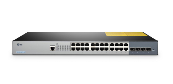
PoE COMPUTER SWITCH
Power over Ethernet (PoE) switch is a network switch that has utilizes Power over Ethernet technology. When connected with other devices, it can support power and data transmission over one network cable at the same time, which greatly simplifies the cabling process. FS offers PoE switches with different port numbers, ranging from 8-port, 24-port to 48-port.
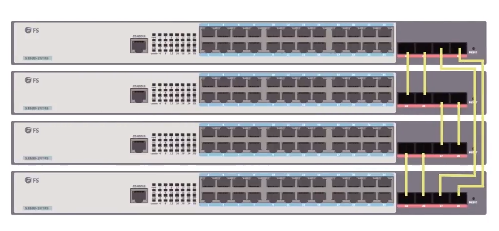
STACKABLE COMPUTER SWITCH
In the large data center, there may be many network applications and also many network switches. It poses great difficulty and triviality to the user to set and maintain each switch. Given this, stackable computer switch rises above the crowd. It enables multiple switches (usually four switches) to work as an individual unit in order to simplify the management, troubleshoot and configuration. This kind of switch can also work standalone switch.
Conclusion
The computer switch is indeed one of the important components of your networking infrastructure. FS offers plenty of fiber switches, PoE switches, or Ethernet-based switches with different port speeds. These switches are great in terms of sales, performance, and quality. To find the right computer switch, turn to our website www.fs.com and consult our expert staff if you have any questions.
Proper cable management is always a must for data center networks to ensure tidy and organized cabling environments. We have introduced fiber optic patch panels, fiber enclosures and other fiber cable management products in previous posts for fiber cabling solution. How about copper cabling solution? This post will introduce copper blank keystone patch panel and its installation method. Also we’ll compare blank patch panel vs preloaded patch panel in order to give you best selection guide for Ethernet cabling.
Figure 1: 12 Cat6 cables and 12 Cat5e cables are terminated on one single 24 port blank patch panel while installed with Cat6 and Cat5e insert modules.
What Is Blank Patch Panel?
Blank keystone patch panel, or unloaded patch panel, is an optional Ethernet patch panel. Different from pre-loaded patch panel with built-in RJ45 ports, blank keystone patch panel is designed with 24/48 reserved holes. The empty slots allow one to install different keystone jackets such as Cat5e/Cat6 insert modules according to his need. Thus the blank patch panel can terminate different cables while different connectors fit on, and one same patch panel enables several types of cables to be connected. All blank keystone patch panels from FS.COM are high density 1U rack mount, no matter 24-port or 48-port. They can easily mounted into a standard 19’’ rack, cabinet or wall bracket. All empty ports are also pre-numbered for easy connection and identification.
Figure 2: Using different keystone jackets or insert modules to customize 24 port blank keystone patch panel.
What Are the Types of Blank Patch Panel?
Generally FS manufactures two types of blank patch panels, with 24/48-port, STP/UTP and Ethernet/multimedia network cabling for option.
For Ethernet cabling only, take this 24 port blank keystone patch panel. The Ethernet patch panel is an unshielded patch panel with 24 blank slots in a compact 1 U. This RJ45 patch panel is used to manage and organize Ethernet cables such as Cat5e patch cables and Cat6 cables.
To enhance network cabling resiliency, consider for blank keystone/multimedia patch panels. The multimedia blank patch panels come witch 48 port patch panel UTP and 24 port patch panel STP/UTP in 1U rack mount in FS.COM. Different from the aforesaid 24 port Ethernet patch panel, their ports accommodate various snap-in jackets, including RJ45 Ethernet, HDMI audio/video, voice and USB applications. This allows users to customize their patch panels for different schemes.
How to Use Blank Patch Panel for Ethernet Cabling?
To use blank keystone patch panels for Ethernet cabling, follow the instructions below.
Choose the proper quantity of Cat6 or Cat5e RJ45 insert modules according to your Ethernet cable types. You have RJ45 insert modules shielded in metal silver and unshielded in various colors for option.
Inlay Cat6 or Cat5e RJ45 insert modules (from the rear panel to the front) into the empty ports on the blank patch panel.
Install the equipped Ethernet patch panel onto a 1U rack with screws and screwdriver.
Plug Cat6 cables or Cat5e cables into corresponding Cat6 modules or Cat5e modules.
Manage cables with the help of cable management accessories such as cable managers, lacing bars and cable ties.
Blank Patch Panel vs Preloaded Patch Panel
Blank keystone patch panel has advantages of personalized setting and installation, which allows one patch panel to terminate different types of cables as long as corresponding insert modules are installed. Say loading both Cat5e and Cat6 insert modules on a 24 port keystone patch panel, then we can terminate both Cat5e and Cat6 cables into matching ports. So blank patch panel is an ideal choice for skillful operators who want to configure his own patch panel for customized cabling requirements.
To seek for a most user-friendly RJ45 patch panel, go for feed through patch panel instead of blank patch panel. Feed through patch panel is an optimized pre-loaded patch panel, which leaves the troubles of punching down wires to the ports required by traditional punch down patch panel. The feed through 24 port patch panel has built-in RJ45 ports both at the front and rear sides for directly terminating Ethernet patch cables. The front ports are marked with sequential numbers for easy identification. The feed through patch panel is an ideal choice for HD cabling environment with convenient and efficient installation requirements. FS feed through patch panels come with Cat6 patch panels and Cat5e patch panels. The Cat6 patch panels are unshielded only whereas the Cat5e patch panels are STP and UTP available.
Conclusion
Blank keystone patch panel is unloaded copper patch panel, which provides customized configuration with different keystone jackets. The various RJ45 insert modules installed on the Ethernet patch panel allow different cables to be terminated. The 24 port and 48 port keystone/multimedia blank patch panels offer copper cabling solution for Ethernet, video/audio, voice and USB applications. For the choice between blank patch panel vs preloaded patch panel, here’s the reference. Blank patch panel is perfect for operators who prefer to configure network patch panels by themselves to cater for their data center cabling. Preloaded feed through patch panel is a better choice for anyone requiring easy and direct access for Ethernet cabling.
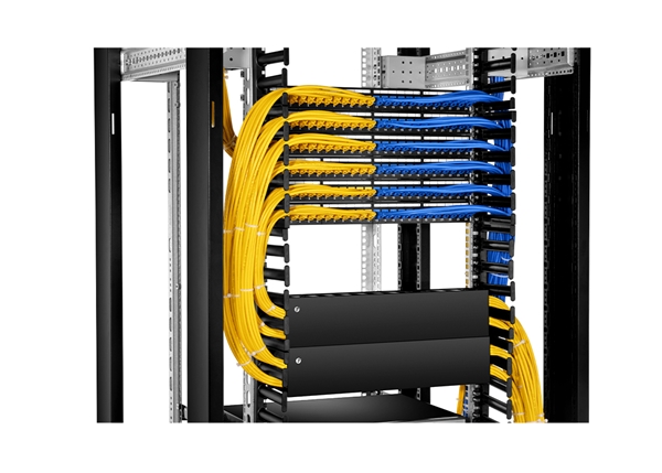
In data centers, we run all enterprise network equipment (server, storage, network switch, etc.) into the server rack. And various wires such as fiber optic cables, Ca5e/6 Ethernet cables and power cords are spreading all over the floor. It’s rather a disaster to see all these cables tangling together without knowing which ends they are tracing to, which is inconvenient for operators to implement troubleshooting. Besides, interwined wires also cause cooling problem, crosstalk and interference, which causes performance issues. Fragile fibers under neglected management will easily break. All these reasons confirmed the necessity of proper cable management. So how to manage cables in server rack?
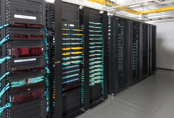
Figure 1: An array of cable management accessories are installed in open server racks to manage cables.
Deploy Proper Server Rack
Above all, estimate your enterprise network scale, cabling numbers and other requirements to choose proper server rack. There are mainly three types of server cabinets in the market, making sure to choose the one for your network environment. All these server racks price are competitive in FS.COM.
Open Frame Server Rack
The open frame rack has no sides and doors to restrict it from reaching the open air. It provides easy access, sufficient open space and airflow for cable management, ideal for high-density cabling for server room and data center racks. You’d better to use open server rack in applications that don’t require security protection for cables. 2-post and 4-post are two types of open frame racks. The former requires less depth whereas the latter supports more weight.
Enclosed Server Rack
The enclosed server rack is a sever cabinet with front and back doors and side panels. The doors can be locked to prevent intentional sabotage and dust invasion. Black server rack 42U/45U is available in FS.COM to offer you with abundant rack cabling space. FS elaborately designs efficient brush guards on the roof to facilitate airflow and ensure better cooling.
Wall Mount Server Rack
Wall mount server rack is used to hold network equipment such as network switch and network accessories such as fiber patch panel. It features functionality to be attached onto the wall to save floor space. FS manufactures 9U/12U 4-post wall mount network cabinets with glass front door. The defect is that wall mount server rack is not as big as other server racks to room large quantity of network devices. In this case bigger network cabinet is the better choice to go. Here is a comprehensive data center cabling solution video guide for your reference.
Deploy Other Cable Management Products in Server Rack
After choosing optimal server racks for your cabling solution, take other cable management accessories into consideration.
Deploy right fiber patch panels or cassettes to terminate your fibers, and use matching fiber enclosures to load them and other enclosure accessories such as fiber slack management spool. An intact loaded fiber enclosure ensures safe entry and exist of fiber patch cables and stores an excess of fibers in a compact of 1U/2U/4U.
Use cable organizer – horizontal cable manager and vertical cable manager to keep scattered running cables in right place and ensure a neat rack environment. Besides, employ cable ties/zip ties to fix wire bundles.
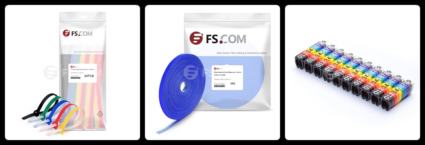
Put emphasis on cable identification tools. Cable ties are available with different colors to help figure different types cables or end devices. Color coded fibers and Ethernet cables are also helpful for recognition. Or you can buy color-coded cable labels with different numbers to mark your wires.
Conclusion
Proper cable management cannot be accomplished in one action. First of all, carefully plan your cabling solution on the basis of your data center scale. Then deploying proper server racks or cabinets and other cable management products – fiber enclosure, fiber patch panel, cable organizer/cable manager, cable ties, cable labels to manage cables shipshape and facilitate cable identification. All these jobs done orderly will make a clean and decent server room, and endow cables and the whole systems with security warranty.
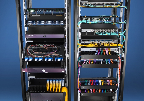
In data centers, cable management is of great concern in addition to functional data transmission devices. A mass of cable wires scattering and tangling together is bothersome for operators to implement maintenance. The neglect of effective cable management also leads to cable damage and low performance issues. To make clean and safe entry and exit for each cable, one must employ proper cable rack manager to ensure an organized and neat rack environment. However there are an array of cable manager products in the market. How to choose right cable manager for rack? This post may help.
Figure 1:Deploying cable manager for rack and other cable management products to make a clean and neat sever room in FS data center.
Overview of Cable Manger for Rack
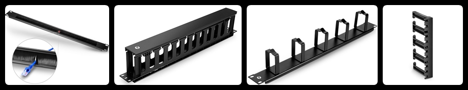
Cable managers own following functions – organizing and protecting running cables, reducing crosstalk and signal interface, facilitating airflow and cooling, and ensuring a clutter-free data center. In general, there are two types of cable manager for rack: horizontal cable manager and vertical cable manager. Further, each type has different styles available to cater for diverse cabling environment. Other cable management products frequently used in collation with cable manager are fiber optic enclosure, fiber patch panel, cable wires, cable labels and so on.
Types of Cable Manager for Rack
Making clear of different types of cable manager for rack helps you to make a wise decision when buying cable management products for racks.
Horizontal Cable Manger
Horizontal cable management panel is often installed in front of equipment such as network switch in parallel. Most cases horizontal cable manager for rack is matched with patch panel and rack-mount enclosure to provide cables a safe and organized pathway from switch ports into the vertical cable manager. And a dozen of wires often bundled with a cable tie to fix loose cables.
Vertical Cable Manager
Rack vertical cable management panel is installed erectly in each side of the cabinet walls to take over cables traversing out of the horizontal cable manager. Usually there are several horizontal cable managers for rack placed in different ladders and two bunches of wires are hanging down from each ladder. Thus the bilateral vertical managers play important role to make a clean multilayer cabinet.
Both horizontal cable manager rand vertical cable manager for rack are installed in a server rack or cabinet to run cables away from equipment neatly. To achieve an optimal rack environment, these two cable rack managers are used together in a server cabinet.
Considerations for Choosing Cable Manager for Rack
In addition to the aforesaid horizontal manager vs vertical cable manager for rack, there are other factors for considering.
Cable Management Environment
If you should deal with massive cables for a big enterprise data center, then you could consider the perfect combination of horizontal cable manager with vertical cable manager for rack in each of your server room cabinet. If you just handle a small business or office cabling, you can choose to save some money by omitting rack vertical cable management deployment.
Rack specification
Server rack usually comes with standard 19-inch wide while depth is flexible in some degree. However rack heights are available with different rack units (1U=1.75 inches) such as 1U, 2U and so on. Accordingly cable manager for rack is designed with different rack units, make sure to buy a right size. Highlights, the bend radius finger bracket can be stacked to reach any heights, ideal choice for high rack environment.
Cable Manager Style
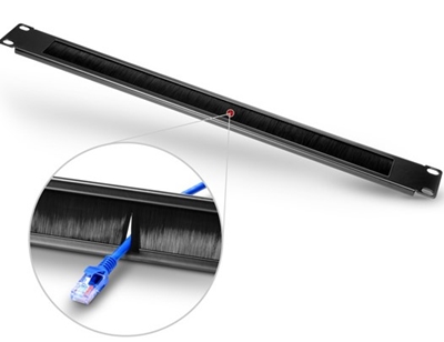
1. To prevent equipment from overheating, choose horizontal cable manager with brush strip to ensure better cooling.
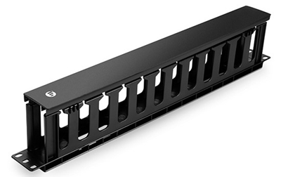
2. For optimal cable care and protection to protect fragile fibers from damage, you can choose horizontal cable manager with finger duct.
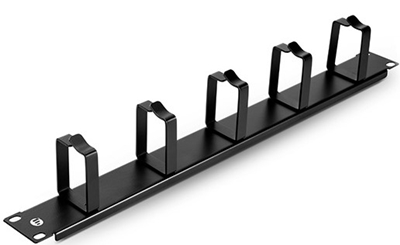
3. To enable flexible routing of massive cords in proper bend radius, pick cable manager with D-ring. It is made with steel for strength and durability, available with 1U and 2 U in FS.COM.
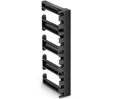
4. For managing different cable types and quantity, choose different styles of cable manager for rack. For example, vertical cable manager with bend radius finger provides extra-deep cable capacity for applications requiring large thick cable bundles (Ethernet cables: Cat5e/6/7). FS 5U 3’’ wide plastic vertical cable manager with bend radius finger owns ultra-high cable capacity up to 23 Cat6 cables.
Conclusion
Cable manager for rack is one of the important cable management products in data centers. Making clear of horizontal cable manager vs rack vertical cable management is the first step for right deployment in cable rack management. Considering your cabling environment, rack specification (esp. U size), and various cable manager styles to cater for special requirements will help you to choose the best cable manager for rack.
In data centers, there are a variety of cable management accessories used in collocation with enterprise network components, such as fiber optic patch panel, fiber optic enclosure and cable ties. In my previous post – Patch Panel vs Switch: What’s the Difference? – I have introduced the role of fiber optic patch panel as a cable management tool. Fiber optic enclosure/fiber optic box is also a frequently used tool for rack cabling solution. This post will introduce fiber enclosure and what we can benefit from it.
What Is Fiber Optic Enclosure?
Fiber enclosure/fiber spice box may refer to an empty box or an intact unit after installation. A loaded fiber optic box contains installed assembly units to connect and separate various fiber optic cables. Usually fiber optic enclosure unloaded comes with 1U/2U/4U available, which can house corresponding quantity of fiber optic cassettes or fiber patch panels. Some people mention fiber optic enclosure and fiber optic patch panel as the same thing since they are matching devices.
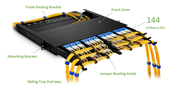
Figure 1: FS slide-out 1U rack mount FHD fiber optic enclosure interior structure in data center fiber cabling application.
What to Benefit From Fiber Optic Enclosure?
Cable Management Function
In general, fiber enclosure functions cable management in data centers for a clean and tidy cabling environment.
It houses and fix fiber optic patch panel or fiber optic cassettes in a box for better management and protection.
Fiber optic enclosure inside accessories such as fiber slack management spool provides a proper bend radius for cables and helps to route, manage and store fibers.
Different types of adapters installed-in enable various incoming fibers to be terminated in high density and protected them from damage.
Optional Design for Different Deployment Scenarios
Fiber optic enclosure has different types available. They may differ from configurations such as fiber enclosure rack mount and fiber enclosure wall mount. Further, rack mount enclosure has different open-close designs, rack unit sizes, and patch panel/cassettes capacities. Different types of fiber optic enclosures cater for different deployment scenarios.
Mount Type Option
Wall mount enclosure usually fits for wall mount applications such as cross-connection in telecommunication room. Fiber enclosure rack mount is a very popular one for rack cabling solution in cabinet.
Slide-out Design
Rack mount enclosures have two models available in FS.COM: slide-out type and cover removable type. By using slide-out rack mount fiber optic enclosure, you don’t need to remove the enclosure from the rack for internal access. The transparent cover also allows fiber check under cover close state. This facilitates cabling management, maintenance and installation process.
High Density
Fiber optic enclosure also provides high density cabling while FHD fiber enclosure rack mount designed. Our FHD fiber enclosures come with 1U, 2U and 4U model, correspondingly housing 4/8/12 FHD fiber adapter panels or 12 x FHD MPO/MTP cassettes and allow terminate 96/192/228 fibers.
Conclusion
Fiber optic enclosure is a box to load fiber optic patch panel/fiber optic cassettes and other accessories in to provide a cable management solution for fiber cabling. Fiber enclosure ensures a tidy cabling environment and protects fragile fibers from outside damage. Also, the elaborate design of various types of fiber optic enclosures allows different deployment scenarios and better caters for specific requirements. Fiber enclosure rack mount or fiber enclosure wall mount enclosure provides optional mount applications. Slide-out and transparent cover enables convenient inspection and maintenance. FHD rack mount fiber optic enclosure offers high density fiber termination in 1/2/4RU options. FHX ultra HD rack mount enclosure achieves high density fiber capacity in space-saving 1RU.