Revolutionize High-Performance Computing with RDMA

To address the efficiency challenges of rapidly growing data storage and retrieval within data centers, the use of Ethernet-converged distributed storage networks is becoming increasingly popular. However, in storage networks where data flows are mainly characterized by large flows, packet loss caused by congestion will reduce data transmission efficiency and aggravate congestion. In order to solve this series of problems, RDMA technology emerged as the times require.

What is RDMA?

RDMA (Remote Direct Memory Access) is an advanced technology designed to reduce the latency associated with server-side data processing during network transfers. Allowing user-level applications to directly read from and write to remote memory without involving the CPU in multiple memory copies, RDMA bypasses the kernel and writes data directly to the network card. This achieves high throughput, ultra-low latency, and minimal CPU overhead. Presently, RDMA’s transport protocol over Ethernet is RoCEv2 (RDMA over Converged Ethernet v2). RoCEv2, a connectionless protocol based on UDP (User Datagram Protocol), is faster and consumes fewer CPU resources compared to the connection-oriented TCP (Transmission Control Protocol).

Building Lossless Network with RDMA

The RDMA networks achieve lossless transmission through the deployment of PFC and ECN functionalities. PFC technology controls RDMA-specific queue traffic on the link, applying backpressure to upstream devices during congestion at the switch’s ingress port. With ECN technology, end-to-end congestion control is achieved by marking packets during congestion at the egress port, prompting the sending end to reduce its transmission rate.

Optimal network performance is achieved by adjusting buffer thresholds for ECN and PFC, ensuring faster triggering of ECN than PFC. This allows the network to maintain full-speed data forwarding while actively reducing the server’s transmission rate to address congestion.

Accelerating Cluster Performance with GPU Direct-RDMA

The traditional TCP network heavily relies on CPU processing for packet management, often struggling to fully utilize available bandwidth. Therefore, in HPC environments, RDMA has become an indispensable network transfer technology, particularly during large-scale cluster training. It surpasses high-performance network transfers in user space data stored in CPU memory and contributes to GPU transfers within GPU clusters across multiple servers. And the Direct-RDMA technology is a key component in optimizing HPC performance, and NVIDIA enhances the performance of GPU clusters by supporting the function of GPU Direct-RDMA.

Streamlining RDMA Product Selection

In building high-performance RDMA networks, essential elements like RDMA adapters and powerful servers are necessary, but success also hinges on critical components such as high-speed optical modules, switches, and optical cables. As a leading provider of high-speed data transmission solutions, FS offers a diverse range of top-quality products, including high-performance switches, 200/400/800G optical modules, smart network cards, and more. These are precisely designed to meet the stringent requirements of low-latency and high-speed data transmission.

How Much Do You Know About Optical Circulator?

What is Optical Circulator?

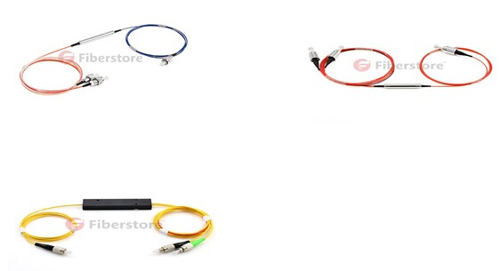
Optical circulator is a non reciprocal device allowing for the routing of light from one fiber to another based upon the direction of the light propagation. It is a special fiber optical component that could be used to separate optical signals in an optical fiber. It usually has at least three ports designed such that light entering any port exits from the next. With its features of high isolation of the input and reflected optical powers, as well as its low insertion loss, optical circulator is widely used in advanced communication systems and fiber optical sensing applications. 3-port optical circulator is the most commonly used optical circulator. In a 3-port optical circulator, there are generally two ports used as input ports and only one port used as output port. Here are some 3-port optical circulator samples shown in the following picture.

optical circulator

Principle of Optical Circulator

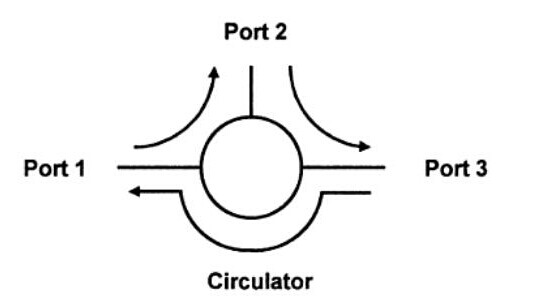
Optical circulator, as a passive element is widely used in fiber optical system. It is usually used to direct the optical signal from one port to another port and in one direction only. This action prevents the signal from propagating in an unintended direction. In a 3-port optical  circulator, a signal is transmitted from port 1 to port 2, another signal is transmitted from port 2 to port 3, finally a third signal can be transmitted from port 3 to port 1. The following picture shows us the working principle of the optical circulator with 3 ports.

principle of optical circulator

Main Features of Optical Circulator
  • High isolation
  • Low insertion loss
  • Low polarization dependent loss
  • Low polarization mode dispersion
  • Excellent environmental stability
Applications of Optical Circulator

Optical circulator can be utilized to achieve bi-directional optical signal transmission over a single fiber. It is a very important optical component which is commonly used in passive optical network, (wavelength division multiplexing) WDM network, polarization mode dispersion, chromatic dispersion compensation, optical add-drop modules (OADM), optical amplifiers, optical time domain reflectometry (OTDR) and fiber sensing applications. Fiberstore offers 3/4 ports polarization-insensitive optical circulator and 1310/1550/1064 polarization-maintaining (PM) optical circulators to satisfy your different applications.

In this blog, we have learnt some basic knowledge of optical circulator. We know that it is usually used to reduce the overall dispersion of light within a fiber-optic system. Especially in passive optical network, optical circulator is in a position to transmit light through the system and use half as much of the fiber to achieve the desired compensating effect while traveling through the system. In a word, optical circulator is an efficient means for conveying a light signal and makes communication systems more convenient and economical.

For more detailed information about optical circulator, welcome to visit our website or contact us over sales@fiberstore.com.

What is the Meaning of 100G Channels Networks to Service Providers

As the traffic demand continues growing, telecom network providers have planned introducing the newly developed coherent 100G transport software in their networks to satisfy the demand. History shows us that network service providers have made use of every stage of the new channel capacity available from equipment developers.

Fiberstore

Fiberstore

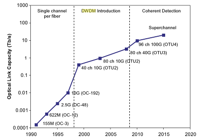
The figure below shows the timeline for increases in fiber link capacity operating provider’s networks. In early 1990s, a capacity of a few hundred Mbps per link and just on channel per strand of fiber inside a transport network was typical. As email was a new communication tool in the centre 1990s, the fiber capacity gradually increased to a couple Gbps, and this growth continued to deal with the demand that individuals needed to start accessing the web. Into the later 1990s, fiber capacity grew even larger with the deployment of 10 Gbps channels and WDM techniques to multiplex and amplify a small number of wavelengths (4-8) on a single fiber pair. In early 2000s, Internet usage became commonplace but networking kept pace using the introduction of DWDM techniques that could support 40, 80, or maybe more wavelengths allowing fiber capacities to be near Tbps. For MUX/DeMUX solutions with different DWDM wavelengths, please visit Fiberstore. This extensive fiber capacity increase helped the transport network support continually increasing user demands. In the late 2000s, the introduction of 40G channels gave the capability of the networks another boost. By 2010, video sharing on the web by applications such as YouTube along with other video when needed (VoD) services started to stress existing network capacity. The development of the fiber capacity to approximately 10 Tbps per fiber. This will address near term capacity requirements, but moving forward, cloud computing along with other bandwidth hungry applications will continue to consume network resources, and new optical techniques to increase channel capacity and optical link capacity is going to be introduced progressively.

Fiberstore

The coherent 100G PM-QPSK system selected by the industry is able to run at the same channel spacing (50 GHz) like a 10G commercial system does in existing networks, and so the 100G system can offer enough capacity for network service providers to support customer demands in the near term without a network overbuild. Using the new 100G system, service providers expect the cost per bit declines in the same rate as or perhaps a faster pace than the decline rate of serves prices service providers can charge their clients, so that providers are able to remain competitive.

Before telecom service providers introduce commercial coherent 100G software in their networks, normally a series of technology trials must be conducted in their existing networks to determine the performance of the new technology. The primary purpose of the technology trials would be to guarantee the 100G channel behaves well in existing fiber network infrastructures. Fiber routes within the field may have high transmission attenuation, high PMD values, multiple connections and splicing points, various fiber types, etc. While most lab experiments are conducted with fiber loop configurations, a linear configuration in field trials is much more preferred to mimic optical links in tangible networks. Field trials give network providers proper expectation for that performance of the systems, which will be installed in networks. Issues present in these trials may also be sent back somewhere developers for further product improvement. In a single field trial a 112 Gbps coherent channel transmitted over 1730 km deployed DWDM link in a service provider’s network, while using DWDM Multiplexer. A carrier suppressed RZ and differential PM-QPSK modulation format was utilized for the channel in the trial. The trial results show that the coherent 100G channel has the capacity to serve long term routes. The plug and play performance of the equipment and robustness to chromatic dispersion and PMD impairments was demonstrated in the trial. Co-propagating the 100G channel with adjacent 10 Gbps signals without touching the fiber infrastructure proved one viable migration road to next generation networks. It’s a requirement for service providers to maintain the networks scalable and cost-effective while increasing channel capacity and fiber ability to have next-gen multi-terabit networks.

In another field trial a real-time, single carrier, coherent 100G PM-QPSK upgrade of the existing 10G/40G terrestrial system was demonstrated inside a service provider’s network. The field experiment shows the performance of the 100G channel sufficient for error-free operation after FEC over installed 900 km and 1800 km fiber links. The experiment proves that flexible and seamless 100 Gps channel upgrades to existing 10G and 40G DWDM systems are possible and practical.

Yet another coherent 100G channel field trial was performed on dispersion shifted fiber (DSF) links. The trial involved eighty 127 Gbps channels propagating on a deployed fiber link. L-band specturn was used to avoid zero dispersion reason for specturn, differnet from using C-band for SMF or NZDSF for additional common cases. The 100G channels, with 50 GHz channel spacing, traveled over 458 km DSF successfully with L-band EDFA only. Sufficient Q-margins remained as left for the 80 channels following the 458 km transmission. This field trial demonstrated that a 10 Tbps calss capacity DWDM product is feasible underneath the condition of small local dispersion by deploying coherent detection and high overhead (20%) coding gain FEC. This trial represented the highest fiber capacity in the field at the time the trial was conducted.

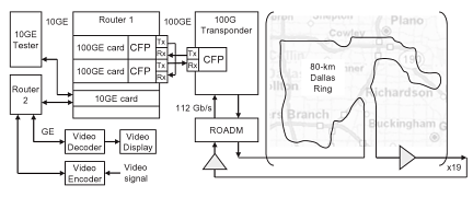
The reason for introducing 100G channels into transport networks is to carry large IP data traffic across IP networks, therefore, an “end-to-end” transport trial, i.e. an entire data transport trial from data equipment to data equipment, using a coherent 100G channel transmission over a long distance, is particularly meaningful to service providers. One such field trial, which involved a worldwide network company, a data equipment developer, a transport equipment developer, and a client interface developer, continues to be reported. In this trial a 112 Gbps single carrier real-time coherent PM-QPSK channel from a transponder carried native IP packet traffic over 1520 km field deployed fiber, with 100GbE router cards and 100G CFP interfaces. This trial shows the feasibility of interoperability between multi-suppliers’ equipment for 100G transport. This field trial, which fully emulated an operating near-term deployment scenario, confirmed that all key components required for deployment of 100GbE technology are maturing at the time the trial was conducted (early 2010).

Fiberstore

The detailed configuration of the trial is shown in the figure. A 10GbE test set generates 10GbE traffic for Router 1 and also the test set can be used for analyzing packet throughput too. Another router (Router 2) is used to accept a GbE signal containing a video signal using a video encoder and to send the recording signal to some video display via a video decoder following the signal transverses the trial path. Router 2 connects to Router 1 with another 10GbE link, containing the video traffic. Router 1 routes both 10GbE data streams to one of the 100GbE cards and routes back the 10GbE data streams form the other 100GbE card towards the corresponding 10GbE ports. The 100G CFP interfaces are used to connect 100GbE cards and the 100G transponder. The transmitter port of the CFP in the first 100GbE card is connected to the receiver port of the CFP in the transponder and also the receiver port of the second 100GbE card is linked to yhe transmitter port from the CFP in the transponder. The receiver port from the CFP in the first 100GbE card and also the transmitter port of the CFP in the second 100GbE card are of a fiber jumper (fiber patch cable) to shut the loop. The CFP transponder sends the 112 Gbps signal towards the fiber route-equipped having a long haul DWDM system. Both directions of the inline amplifiers have been used for the trial to save on equipment needed.

With these successful 100G system field trials, telecom network providers and other network operators have been convinced that the only optical carrier PM-QPSK with coherent detections is easily the most promising 100G channel solutions, at least for the time being. Now commercial 100G systems are for sale to the customers of the equipment developers and the customers are likely to enjoy the ten times fiber capacity begin their networks.


Optical Module Will Be Shine In The Field of Data Communications

With the current amount of data has been too large to be collected, stored, managed and analyzed using traditional tools, the era of big data is coming. To meet the challenges of big data, cloud computing network technology application virtualization technology is the inevitable trend of development, cloud computing and data center network cabling system to build, then adapted to the era of big data network infrastructure requirements. Faced with massive data storage and data processing, and data centers in order to improve the efficiency of resource use computing power and data analysis, the extensive use of virtualization, cloud computing power and data analysis, the extensive use of virtualization, cloud computing technologies, including server virtualization, network virtualization technology and storage virtualization technology etc.

The network is the foundation of all the data flow, closely related to the development of large data generation and network technology. Accordingly, the large data transfer rate is closely related to the network, and therefore a higher demands of the optical module. In general, the core layer using 40G/100G, access layer with the method of 10G basic has become the direction of the network upgrade.

Take a look at the sales volume of 10G optical transceivers. Although 100G and 40G sals growth is more attention, but 10G optical transceiver sales still set a new record in 2013. 10G optical
transceiver demand is very strong at short distances, which pushed up overall in 2013 the 10G module shipments will exceed 10 million, up 40% from last year. This will also be a short distance 10G module shipments 1G short distance beyond the first year, the data show that the 10G connector will have a larger market share.

There are many factors encourage the growth of 100G and 40G, the Ethernet transceiver market growth prompted 40G and 100G growth in shipments. However, due to the rapid decline in FTTx market, in 2013 the optical transceiver market as a whole will be flat. Many manufacturers have said the 2013 report of EPON and GPON ONU a significant reduction in volume, although sales remained stable OLT. Global optical transceiver market, including 10G, 40G and 100G transceiver, 2012 increaded 10% to $1.63 billion.

Optical module growth space is large especially the data communication field

2013 data communications optical components and modules for sales growth of 20%, and in 2012 was 16%. But the telecom optical components and modules market is still sleeping, in 2012 and 2013 grew by only 3%. For the upcoming 2014, the telecommunications market is likely to be better.

40G optical transceiver sales in 2013 increased by more than three times, mainly like Google has a large data center for its large demand. 100G DWDM transponder current price is 30 times 10G DWDM transceiver. However, 100G wide area, and some are laying metro network applications, because it can create additional value for network operators. WAN, 100G maximize the transmission capacity of optical fiber has been deployed, and in the next 10 years, it will not become obsolete. A core router 100G port can be connected with 10 different 10G ports. This is 100G optical device to another value of core network.

And we have learned, Facebook, Google, Microsoft and other multinational companies, have their own cloud data centers, coupled with governments agencies also commissioned by the network operator to build a public cloud centers, etc., the future applications in the data center business opportunities in the field of the cloud is still in the growth, therefore, in the next few years optical transceiver module, AOC and other products are growing space.

Cisco has also stepped up its efforts in building the data center. Cisco continued to increase in recent years of data construction, revenue accounting for its data center products increased year by year the proportion of revenue, below shows the Cisco 2011 to the first quarter of 2013 accounted for a quarter of data revenue from product revenue proportion charts. In addition, in June this year Composite cisco’s $180 million acquisition of the data processing companies, also shows that the emphasis on data center.

Data center optical module, the device corresponding to the high demands, it is understood, the China manufacturers are already some devices, such as cooperation with Baidu supply module with a data center. One of the requirements of the data center optical devices are high-speed, server interfaces are from 1G to 10G, and aggregation switches from 10G to 40G/100G; Second, the cost is low, because the data center requires a lot of applications; third requirement is also lower power consumption, because the power consumption is very large data centers. Therefore, the device should adapt to the data provider development needs of server interfaces and aggregation switches to upgrade and evolution; improve production efficiency to reduce costs and reduce power consumption components.

As an professional manufacturer & provider of fiber optic transceivers, we supply sfp transceiver module, xfp transceiver module etc. what’s more we also supply other fiber optic products, such as dwdm muxfiber pigtails, fiber optic testers and tools and so on.

Fiber Transmission Communication Network – Optical Terminal Box

Optical Fiber Termination Box in short OTB, optical terminal box is mainly used for the cable ends fixed, cable and pigtail splice and the remainder fiber asylum and protection. The communication network of fiber optic transmission optical cable terminal box series terminal wiring of auxiliary equipment, suitable for indoor fiber optic cable directly and branching connection of the fiber optic connector play a protective role.

The Material Performance

Optical cable terminal box where the parts are made of materials should have anti-corrosion properties, such as corrosion resistance should be treated with preservatives; Its physical and chemical properties must be stable; must be compatible between the various materials.

And sheath compatible with the cable jacket and wiring pigtail. In order to prevent corrosion and other electrical damage, these materials must also be compatible with other commonly used materials in the device.

Appearance of cable terminal box should be completer shape, no glitches, no bubbles, no cracks and voids, meta-warping element impurities and other defects. All background color shold be uniform and continuous. Beautiful appearance, convenient construction connecting additional attenuation reasonable structure, the fiber to strengthen the core fixed in the terminal box, cable metal outer sheath connected ground wire leads function applies to both the ribbon cable and fiber optic cable. Unique design, the terminal box on the 19-inch, wall-mounted terminal box.

Cable terminal box of the optical properties of the remaining fiber is coiled in the set fibers and optical fiber and fiber optic connectors, fiber optic terminal box installation of the operating additional attenuation.

Mechanical properties after the following tests, the cable terminal box box body and box should change, if necessary, for the fiber-ray examination.

1.Stretch: cable terminal box with a fiber optic cable should be able to withstand the axial tensile strength of not less than 500N, with either a wiring pigtail can withstand axial tensile strength of not less than 5N.
2. Flattening: The cable terminal box on each side of the box body should be able to withstand the vertical static pressure of not less than 200N.
3. Torsion: cable terminal box should be able to withstand the torsion angle.

Electrical performance

1. Insulation resistance: Cable connector box of metal components and optical metal reinforcing core fiber optic cable between the metal components, the insulation resistance between the cable metal parts and ground should not be less than 2 * 104MΩ [test voltage of 500V (DC).

2. Dielectric strength: cable terminal box with cable metal strengthening core fiber optic cable between the metal components, cable metal structures between the role of 15KV DC 1min, no breakdown, no flashover.

Optical Performance

The remaining fiber cable terminal box is coiled within the splice tray fiber and fiber optic connectors, cable terminal box installation of the operating there should be no additional attenuation.

Function

The splice closure is two pieces of fiber optic cable connection. The terminal box is the tip of the cable access, and then through the patch cord access optical switch. Therefore, the terminal box is usually installed in the 19-inch rack can accommodate fiber optic cable ends quantity more. The splice closure is two pieces of fiber optic cable connection. Terminal box is connected to the fiber optic cable with pigtail play a protective role. Indoor terminal box can be used for practical work with but very little splice closure when the terminal box uses not the same. 1. the transfer box can be divided into the cable transfer box and cable boxes. Their role in the user front-end wiring use. 2. Breakout boxes generally refers to the splice box, also known as fiber optic splice closure in some places, especially radio and television system, also known as optical splice pack, its role is to protect the cable connector does not damage by the outside world. Patch panel fiber optic patch panels and cable distribution frame, the role like the transfer case, but it is used in the engine room of the operators.

Application

Optical cable terminal box as a carrier of information transmission, fiber optic hardware as an information transmission medium, has become an important pillar of modern communication. optical cable terminal box technology from theory to the field of engineering technology experienced a few decades, to the realization of today’s high-speed fiber-optic communications, before and after the birth of the fiber-optic communications technology and in-depth development of information and communication in the history of an important reform.

Optical cable terminal box is widely used in telephone, if farmers network systems, data, image transmission system, CATV cable TV series for indoor fiber optic cable through power connection and branch connection, play a pigtail disc storage and protection of joint role, made of cold-rolled steel plate electrostatic spray, design, reasonable structure, appearance before a large fiber to strengthen the core fixed in the terminal.