EPON SFP VS. GPON SFP: Cost-effective Solution for Access Network

With the increasing demands for higher capacity, more diversity and more personalization of services, the capacity and versatility of access networks needs to be expanded. Passive optical network (PON), as a major technology of FTTH, offers point-to-multipoint (P2MP) network access with lower installation and maintenance costs. EPON (Ethernet PON) and GPON (Gigabit PON) are popular versions of PONs at present. The related technologies keep developing and meanwhile the market of PON components keep growing. PON transceiver (EPON SFP or GPON SFP) is an essential part of PON system, in which a single fiber from a central office optical network unit (ONU) is connected to optical network terminals (ONTs) or optical network units (ONUs) at costomer premises. EPON SFP vs. GPON SFP is today’s main subject matter of this paper.
EPON SFP VS. GPON SFP

Passive Optical Network (PON)

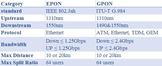
Passive optical network (PON) is a form of fiber-optic access network. As the leading technology being used in FTTx (FTTH) deployments, so it is also called FTTH (fiber to the home) network. The typical PON arrangement is a point to multi-point (P2MP) network where a central optical line terminal (OLT) at the service provider’s facility distributes TV or Internet service to as many as 16 to 128 customers per fiber line. A PON reduces the amount of fiber and central office equipment required compared with point-to-point architectures. PON only uses fiber and passive components, thus it costs significantly less than those using active components. However, a PON has a shorter range of coverage limited by signal strength, which is typically limited to fiber cable runs of up to 20 km (12 miles). There are two different solutions developed by the IEEE and ITU-T – EPON and GPON. The main differences between them lie in the protocols used for upstream and downstream communications. The following table shows the detailed information about EPON vs. GPON.
EPON vs. GPON

Table 1: EPON vs. GPON

What Is PON Transceiver?

PON transceiver is a bi-directional optical transceiver that uses different wavelengths to transmit and receive signals between the OLT at the CO and the ONUs at the end users’ premises over a single fiber. According to the pluged-in device, PON transceiver can be divided into OLT transceiver module and ONU transceiver module with SFF, SFP/SFP+ or XFP package. Here mainly introduce two common OLT transceivers used in GPON or EPON network: GPON SFP and EPON SFP.
GPON SFP

GPON SFP

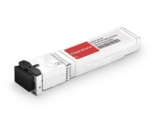
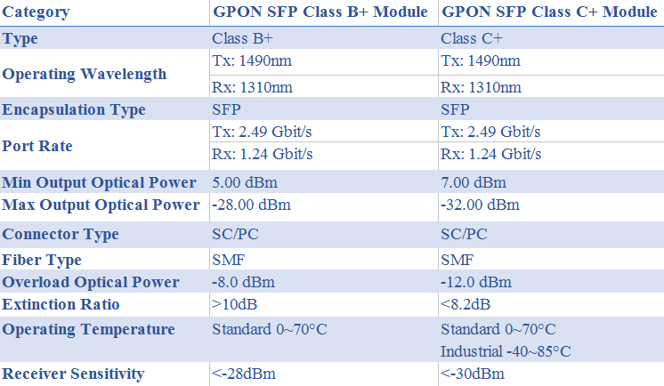
GPON SFP OLT transceiver is designed for OLT side in GPON network. GPON SFP uses 1490nm continuous-mode transmitter and 1310nm burst-mode receiver. The transmitter section uses a 1490nm DFB (Distributed Feed Back) LD with automatic power control (APC) function and temperature compensation circuitry to ensure stable extinction ratio overall operating temperature range. And it is Class I laser compliant IEC825 and CDRH standards. The receiver has a hermetically packaged burst-mode APD-TIA (trans-impedance amplifier) pre-amplifier and a burst-mode limiting amplifier with LVPECL compatible differential outputs. The GPON OLT SFP transceiver is a high performance and cost-effective module for serial optical data communication applications to 2.5Gpbs. For GPON transceivers, there are 2 Class available – Class B+ and Class C+. The table below shows the key differences between GPON SFP class B+ and class C+:
GPON SFP class B+ vs. class C+

Table 2: GPON SFP class B+ vs. GPON SFP class C+

EPON SFP

EPON SFP transceiver is the family of high performance optical modules providing a symmetric 1.25 Gb/s downstream and 1.25 Gb/s upstream data link over a single fiber using a 1490 nm continuous-mode transmitter and 1310 nm burst-mode receiver. The transmitter section uses a 1490nm DFB laser for superior performance and is Class 1 laser compliant. The receiver section uses a 1310nm APD, pre-amplifier, and limiting post-amplifier. The receiver does not require a reset pulse between incoming optical packets of varying signal strength. EPON SFP OLT transceivers support 1000BASE-PX20-D for 20 km applications.

EPON SFP VS. GPON SFP

In terms of OLT module, there are many similarities through EPON SFP vs. GPON SFP, such as type of laser, transmission distance and communication model. The key difference among them is the sending power and receiver sensitivity. The sending power of GPON SFP Class B+ is 1.5~5dBm, and its receiver sensitivity is -28dBm while the sending power of Class C+ is 3~7dBm and receiver sensitivity is -32dBm. The sending power of EPON SFP is 2~7dBm and its receiver sensitivity is -28dBm. For GPON SFP, the upstream bandwidth is scalable from 155Mbps to 2.5Gbps while the downstream is designed to deliver 1.25Gbps or 2.5Gbps. It is the most widely used consumer broadband service in FTTH networks of present times. On the other hand, EPON SFP supports symmetric bandwidth of 1.25Gbps in both the upstream and downstream directions.
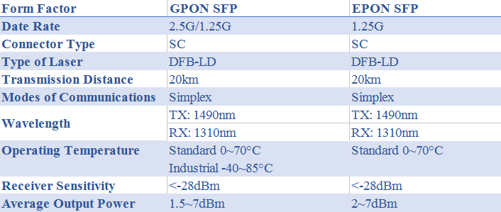
EPON SFP VS. GPON SFP

Table 3: EPON SFP vs. GPON SFP

Conclusion

Through EPON SFP VS. GPON SFP, we can see that they are the same in architecture but for different data rate and applications. In terms of cost, The GPON SFP optical module is more expensive than EPON SFP. Because the GPON chipsets available in the market are mostly based on FPGA (Field Programmable Gate Array), which is more expensive than the EPON MAC (Media Access Control) layer ASIC. When GPON reaches deployment stage, the estimated cost of a GPON OLT is 1.5 to 2 times higher than an EPON OLT. For the users who have demands of multi-service, high QoS and security, as well as ATM backbone network, GPON SFP seems to be an ideal. And for the one who is much care about the cost and has less security requirements, EPON SFP may be better.

Related Article: Passive Optical Network Tutorial

How to Expand Bandwidth in PON Network with CWDM Technology?

PON (passive optical network) is one of a common optical fiber network architectures. It is characterized by the “splitting” of the optical fiber one or more times, resulting in the sharing of optical fiber among multiple users. However, as networks grow in terms of subscriber counts, the scope and number of services offered, expanding the network bandwidth is inevitable. Coarse Wave Division Multiplexing (CWDM), known for its low cost and scalability to increase fiber capacity as needed, is a preferred method for PON network expansion. This article will focus on using CWDM technology to overcome bandwidth limitations in PON access networks.

CWDM Mux/Demux and OADM (Optical Add-Drop Multiplexer) in Access PON

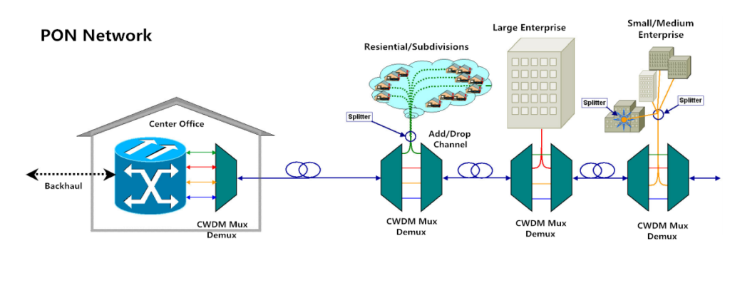
Fibers in a PON are typically shared with several users. Hence the bandwidth of the fiber originating at the CO (center office) is shared among a group of users. The splitting of the network is accomplished by optical splitters. These splitters can split the fiber 2-32 times, which may introduce high losses in the network. Besides, as different places in a same network need different wavelengths, CWDM Mux is often deployed to multiplex these signals on a single fiber.

In PON (Passive Optical Network) network, whether in ring structures or point-to-point arrangements, different optical nodes need specific wavelengths. Therefore, at each node, a CWDM OADM is used to drop or add certain channels from the fiber as required,. Then the signals will be transmitted to the user through optical fibers. The following picture shows a simple PON network.

PON

How to Expand Bandwidth of PON Network Using CWDM Technology?
Upgrading Access PONs Using Passive CWDM Mux/Demux

In PON networks, OLT has two float directions: upstream (getting an distributing different type of data and voice traffic from users) and downstream (getting data, voice and video traffic from metro network or from a long-haul network and send it to all ONT modules on the ODN).

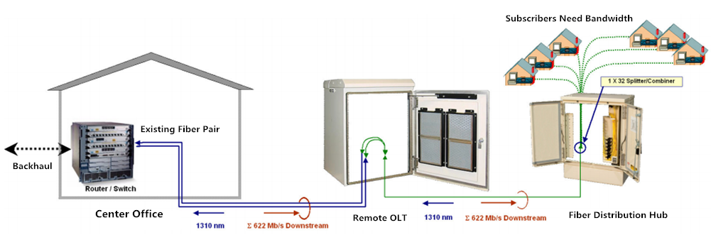
The following figure represents a situation where existing subscribers intend to upgrade to higher value added bandwidth services. In order to satisfy customers’ needs for IPTV, VoIP, video on demand etc., the 622 Mb/s downstream capacity between the CO and the OLT, providing roughly 20 Mb/s to each subscriber, must increase.

PON network

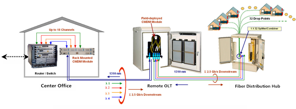
Considering there may be new subscribers and services added, the targeted bandwidth requires at least a downstream CO/OLT link bandwidth of 2.5Gb/s. Therefore, four CWDM wavelengths are introduced to multiply the channels passing between the CO and OLT. This introduction of passive CWDM Mux/Demux can relieve the fiber exhaust effectively. The below figure shows the upgrading process.

PON upgrade

Advantages of This Upgrade

Compared with laying a new fiber cable, the upgrade with passive CWDM is easily accomplished within hours after some modest investment in network planning. And the sum of material, labor, equipment and training expense is far less, which explain why many enterprises, private business users of LAN and data storage networks use passive CWDM too.

Expanding EPON Bandwidth Using CWDM Mux/Demux

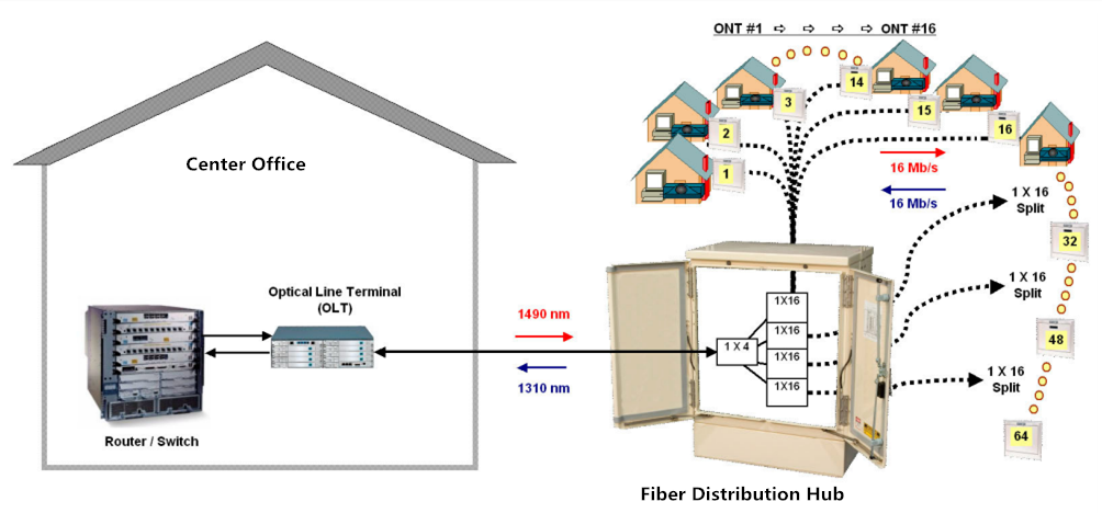
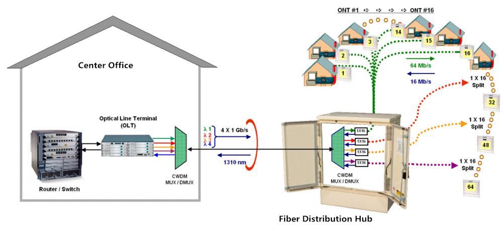
EPON stands for Ethernet passive optical network. It is an enabling technology that benefits consumers. Here is an EPON network, which was conceived to serve up to 64 subscribers. All users share a single bidirectional optical feed line. With the need for IPTV, HDTV and other higher bandwidth services growing, the downstream capacity 16Mb/s should be improved.

EPON

The picture below shows the same EPON deployment upgraded to 4Gb/s bandwidth capacity.

EPON network

This upgrade uses 4 channels passive CWDM Mux/Demux to extend the whole network capacity, allowing the downstream capacity increase four times without affecting the upstream traffic.

Advantage of This Expansion

Using CWDM Mux/Demux effectively increases the network bandwidth capacity and reduces the cost. At the same time, it requires minimal modification of the existing infrastructure, which also saves labors.

Summary

CWDM technology offers significant benefits of low investment, minimal operating cost and very simple and straightforward upgrade planning and implementation. In addition, passive CWDM also provides scalability and network flexibility for network growth and bandwidth demands in the future. FS.COM supplies different channels of CWDM components. Welcome to contact us via sales@fs.com.

Related article:Examples of CWDM Network Deployment Solution

Passive Optical Network – a Superior Network Solution

With the explosive growth of Internet, the introduction of a broadband access network based on fiber-to-the-office (FTTO) and fiber-to-the-home (FTTH) has been triggered. Under this circumstance, access and metro networks should be scalable in terms of capacity and accommodation as well as flexible with regard to physical topology. Passive optical network (PON), one class of fiber access system, can deal with the various demands.

Definition

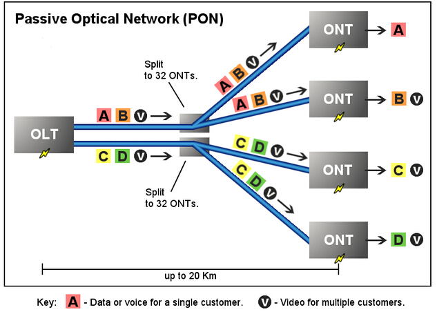
A passive optical network (PON) is a telecommunication network that uses point-to-multipoint fiber to the end-points in which unpowered optical splitters are used to enable a single optical fiber to serve multiple end-points. It consists of an optical line terminal (OLT) at the service provider’s central office and a number of optical network units (ONUs) or optical network terminals (ONTs), near end users (see the figure below). PON takes advantages of wavelength division multiplexing (WDM) and uses one optical wavelength for upstream traffic while another for downstream traffic on a single-mode fiber. The upstream signals are combined at the splitters by using a multiple access protocol (time division multiple access). The downstream signals are directed to multiple users by using passive optical splitter technology.

passive optical network
Advantages

Signals in a shared fiber architecture can be split out using two methods. One is active Ethernet (AE), with which the individual signals are split out using electronic equipment near the subscriber. The other one is PON, in which the signals are replicated passively by the splitter. Compared with AE, a network based on a PON system is more superior. The advantages of PON are as below.

PON incurs lower capital expenditures because it has no electronic components in the field. Also PON lowers the operational expenditures as there is no need for the operators to provide and monitor electrical power in the field or maintain backup batteries. Besides, a PON has a higher reliability because in the PON outside plant there are no electronic components which are prone to failure. Additionally, one of the most crucial features of a PON-based access network is its signal rate and format transparency. It is much simpler for a PON to upgrade to higher bit rates. Both AE and PON require upgraded electronics in the central office (CO) and customer premises, but unlike AE, PON does not need to upgrade in the outside plant as the passive splitters are agnostic to PON speed. Lastly, a PON solution has the ability to span long distances without degrading performance. The low-loss characteristics of single-mode fiber enable PON to support a maximum physical reach of 20 kilometers.

Applications

There are some applications for which PON is well suited, such as fiber-to-the-home (FTTH) delivery of voice, Internet data, and cable access broadband video. More specifically, PON is used when the applications require anticipated system to upgrade to high-security areas or where the rerouting of cable may be difficult. Or in the cases that installations involving widely dispersed nodes require long runs of fiber. And PON is utilized for the projects where costs, especially initial deployment costs, are a key concern. At the same time, using PON can help user bandwidth to be adequately managed.

By reading the above illustration, have you got a basic understanding about the passive optical network? Fiberstore, a professional manufacturer and supplier in the optical industry, has many high-quality PON products including PON splitters, optical network units and optical line terminal. Choosing a PON product in Fiberstore can help to deploy your network more efficiently.

How Much Do You Know About Optical Circulator?

What is Optical Circulator?

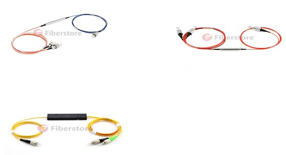
Optical circulator is a non reciprocal device allowing for the routing of light from one fiber to another based upon the direction of the light propagation. It is a special fiber optical component that could be used to separate optical signals in an optical fiber. It usually has at least three ports designed such that light entering any port exits from the next. With its features of high isolation of the input and reflected optical powers, as well as its low insertion loss, optical circulator is widely used in advanced communication systems and fiber optical sensing applications. 3-port optical circulator is the most commonly used optical circulator. In a 3-port optical circulator, there are generally two ports used as input ports and only one port used as output port. Here are some 3-port optical circulator samples shown in the following picture.

optical circulator

Principle of Optical Circulator

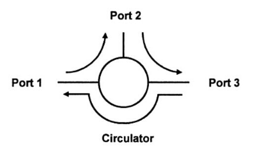
Optical circulator, as a passive element is widely used in fiber optical system. It is usually used to direct the optical signal from one port to another port and in one direction only. This action prevents the signal from propagating in an unintended direction. In a 3-port optical  circulator, a signal is transmitted from port 1 to port 2, another signal is transmitted from port 2 to port 3, finally a third signal can be transmitted from port 3 to port 1. The following picture shows us the working principle of the optical circulator with 3 ports.

principle of optical circulator

Main Features of Optical Circulator
  • High isolation
  • Low insertion loss
  • Low polarization dependent loss
  • Low polarization mode dispersion
  • Excellent environmental stability
Applications of Optical Circulator

Optical circulator can be utilized to achieve bi-directional optical signal transmission over a single fiber. It is a very important optical component which is commonly used in passive optical network, (wavelength division multiplexing) WDM network, polarization mode dispersion, chromatic dispersion compensation, optical add-drop modules (OADM), optical amplifiers, optical time domain reflectometry (OTDR) and fiber sensing applications. Fiberstore offers 3/4 ports polarization-insensitive optical circulator and 1310/1550/1064 polarization-maintaining (PM) optical circulators to satisfy your different applications.

In this blog, we have learnt some basic knowledge of optical circulator. We know that it is usually used to reduce the overall dispersion of light within a fiber-optic system. Especially in passive optical network, optical circulator is in a position to transmit light through the system and use half as much of the fiber to achieve the desired compensating effect while traveling through the system. In a word, optical circulator is an efficient means for conveying a light signal and makes communication systems more convenient and economical.

For more detailed information about optical circulator, welcome to visit our website or contact us over sales@fiberstore.com.

DO You Know Variable Optical Attenuator?

Optical Attenuator is one part of passive optical components. It’s widely used in fiber optic communications to reduce optical fiber power at a certain level. Variable optical attenuator is one of optical attenuator. Now I would like to introduce some basic knowledge of variable optical attenuator in this blog.

what is Variable Optical Attenuator?

Variable Optical Attenuator (VOA) is a double window (1310/1550nm) of passive optical components. Variable optical attenuator could continually and variably attenuate the light intensity in the optical fiber transmission. Variable optical attenuator cable could help simulate distance or actual attenuation in the fiber optic testing work by inserting a calibrated attenuation into the link. By using the variable optical attenuator (VOA), technicians could verify the power margin received by testing the fiber optic link power budget. Fiber optic VOA can help the user vary the light power injected from a light source into the optical fiber.

VOA type

Principle of Variable Optical Attenuator

The power reduction is done by such means as absorption, reflection, diffusion, scattering, deflection, diffraction, and dispersion, etc. Variable optical attenuator usually works by absorbing the light, like sunglasses absorb the extra light energy. It typically gets a working wavelength range in which they absorb the light energy equally. They should not reflect the light since that could cause unwanted back reflection in the fiber system. Or by scattering the light such as an air gap. Another type of attenuator utilizes a length of high-loss optical fiber. It operates upon its input optical signal power level in such a way that its output signal power level is less than the input level.

Built-in Variable Optical Attenuator

Variable optical attenuator may be either manually or electrically controlled. A manual device is useful for one-time set up a system, and is a near-equivalent to a fixed attenuator, and may be referred to as an “adjustable attenuator”. In contrast, an electrically controlled attenuator can provide adaptive power optimization.

Attributes of merit for electrically controlled devices, include speed of response and avoiding degradation of the transmitted signal. Dynamic range is usually quite restricted, and power feedback may mean that long term stability is a relatively minor issue. Speed of response is a particularly major issue in dynamically reconfigurable systems, where a delay of one millionth of a second can be expected to result in the loss of large amounts of transmitted data. Typical technologies employed for high speed response include LCD, or Lithium niobate devices.

With this blog, we have learnt the basic knowledge of variable optical attenuator.  It is necessary to use in fiber optical communications. Fiberstore is a professional supplier of fiber optic communication solution. Variable optical attenuator is just one of PON(passive optical network) components. For more information about variable optical attenuator, welcome to visit our website or contact us over sales@fiberstore.com.

FTTX PON – the Replacement of Copper Network

Introduction

FTTX (Fiber-To-The-X) is know as different Passive Optical Network (PON) configurations which can be used to describe any optical fiber network that replaces all or part of a copper network. It is different from the traditional fiber optic network used for Local Area Network (LAN) applications.

A key difference between FTTX and the traditional fiber optic network is the number of optical fibers required for each user. In most FTTX applications, only one optical fiber is used. The single optical fiber passes data in both directions (bidirectional, or BiDi). This is very different from a LAN application where the transmit optical fiber sends data in one direction and the receive optical fiber sends data in the other direction. In a LAN application, both optical fibers can have data passing through them at the same time.

1000BASE-T SFPA transceiver, or converter, is typically a device that has two receptacles or ports. One mates with the transmit optical fiber and the other mates with the receive optical fiber. This allows the device to be transmitting and receiving simultaneously. This is known as full-duplex operation, e.g., a 1000BASE-T SFP transceiver with a RJ45 port can take advantage of this operation. In an FTTX single optical fiber application, full-duplex operation is typically not possible; usually only half-duplex operation takes place. This means that part of the time the optical fiber is carrying a signal in one direction, and the rest of the time, it is carrying a signal in the other direction. The key to making this system work is timing. Data is sent downstream for a predetermined amount of time and then data is sent upstream for a predetermined amount of time. This process is also known as Time Division Multiplexing (TDM).
FTTX systems typically use multiple wavelengths. The downstream laser is always a different wavelength than the upstream laser. The downstream laser is typically the longer wavelength, such as 1480 nm or 1550 nm (or both), and the upstream laser is typically 1310 nm. FTTX is possible with optical fiber distances up to 20 km because optical fiber is capable of transmitting information with a very low level of loss. The typical loss for an FTTX optical fiber at 1550 nm is 0.25 dB/km and 0.35 dB/km at 1310 nm.

Types of FTTX

According to the X, there are Fiber-To-The-Home (FTTH), Fiber-To-The-Building (FTTB), Fiber-To-The-Curb (FTTC), Fiber-To-The-Node (FTTN), Fiber-To-The-Desk (FTTD), etc.

FTTH

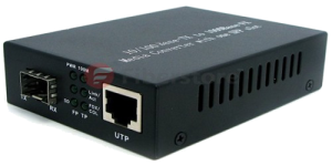
Fiber to Copper Media ConverterAn FTTH PON uses optical fiber from the central office to the home; there are no active electronics helping with the transmission of data in between the two locations. The central office is a communications switching facility. It houses a large number of complex switches that establish temporary connections between subscriber lines that terminate at the central office. At the home, a converter box (e.g., a Fiber to Copper Media Converter with SFP and RJ45 ports) changes the optical signal from the optical fiber into electrical signals. The converter box interfaces with existing home cabling such as coaxial cabling for cable TV, twisted-pair cabling for telephone, and Category 5e or 6 cabling for Internet connectivity.

FTTB

An FTTB PON is very similar to an FTTH PON. It uses optical fiber from the central office to the building and there are no electronics helping with transmission in between. The optical signal from the optical fiber is converted into electrical signals in a converter box at the building. The converter box interfaces with existing cabling such as coaxial cabling for cable TV, twisted-pair cabling for telephone, and Category 5e or 6 cabling for Internet coonectivity.

FTTC

In an FTTC PON, optical fiber runs from the central office and stops at the curb. The “curb” may be right in front of the house or some distance down the block. The converter box is located where the optical fiber stops, and it changes the optical signal from the optical fiber into electrical signals. These electrical signals are typically brought into the home through some existing copper cabling. The electrical signals may need to be processed by another converter box inside the house to interface with existing cabling such as coaxial cabling for cable TV, twisted-pair cabling for telephone, and Category 5e or 6 cabling for Internet coonectivity.

FTTN

FTTN is sometimes referred to as fiber to the neighborhood. An FTTN PON only has optical fiber from the central office to the node. The node is typically a telecommunications cabinet that serves a neighborhood or section of a neighborhood. The optical signal from the optical fiber is converted into electrical signals inside the telecommunications cabinet. These electrical signals are distributed throughout the neighborhood through existing copper cables to the houses.

FTTD

FTTD is a ideal of FTTX solution. Fiber connection is installed from the main computer room to a terminal or fiber media converter near the user’s desktop. FTTD is a high-bandwidth solution that expands the traditional fiber backbone system by running fiber directly to desktops. It is a horizontal wiring option that pushes the available bandwidth beyond 10G. It is an intriguing, underestimated and overlooked way to create a beneficial system that is expandable and performance-driven.

Fiberstore’s FTTX Solutions

As more bandwidth is needed for digital voice, high-speed data and high-definition video, service providers can count on Fiberstore’s innovative optical infrastructure solutions to meet today’s challenges and prepare for tomorrow’s demands. Fiberstore offers a variety of options to achieve “end-to-end” FTTX architectures that can transmit voice, data and video through the PON technologies. Fiberstore’s FTTX solutions include CWDM & DWDM multiplexers/demultiplexers, transceivers (e.g., SFP, SFP+, XFP), media converters, cables etc.

Article Source: http://www.fiberopticshare.com/passive-and-active-network-fundamentals.html