Passive Optical Network – a Superior Network Solution

With the explosive growth of Internet, the introduction of a broadband access network based on fiber-to-the-office (FTTO) and fiber-to-the-home (FTTH) has been triggered. Under this circumstance, access and metro networks should be scalable in terms of capacity and accommodation as well as flexible with regard to physical topology. Passive optical network (PON), one class of fiber access system, can deal with the various demands.

Definition

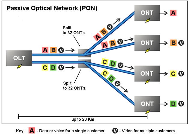
A passive optical network (PON) is a telecommunication network that uses point-to-multipoint fiber to the end-points in which unpowered optical splitters are used to enable a single optical fiber to serve multiple end-points. It consists of an optical line terminal (OLT) at the service provider’s central office and a number of optical network units (ONUs) or optical network terminals (ONTs), near end users (see the figure below). PON takes advantages of wavelength division multiplexing (WDM) and uses one optical wavelength for upstream traffic while another for downstream traffic on a single-mode fiber. The upstream signals are combined at the splitters by using a multiple access protocol (time division multiple access). The downstream signals are directed to multiple users by using passive optical splitter technology.

passive optical network
Advantages

Signals in a shared fiber architecture can be split out using two methods. One is active Ethernet (AE), with which the individual signals are split out using electronic equipment near the subscriber. The other one is PON, in which the signals are replicated passively by the splitter. Compared with AE, a network based on a PON system is more superior. The advantages of PON are as below.

PON incurs lower capital expenditures because it has no electronic components in the field. Also PON lowers the operational expenditures as there is no need for the operators to provide and monitor electrical power in the field or maintain backup batteries. Besides, a PON has a higher reliability because in the PON outside plant there are no electronic components which are prone to failure. Additionally, one of the most crucial features of a PON-based access network is its signal rate and format transparency. It is much simpler for a PON to upgrade to higher bit rates. Both AE and PON require upgraded electronics in the central office (CO) and customer premises, but unlike AE, PON does not need to upgrade in the outside plant as the passive splitters are agnostic to PON speed. Lastly, a PON solution has the ability to span long distances without degrading performance. The low-loss characteristics of single-mode fiber enable PON to support a maximum physical reach of 20 kilometers.

Applications

There are some applications for which PON is well suited, such as fiber-to-the-home (FTTH) delivery of voice, Internet data, and cable access broadband video. More specifically, PON is used when the applications require anticipated system to upgrade to high-security areas or where the rerouting of cable may be difficult. Or in the cases that installations involving widely dispersed nodes require long runs of fiber. And PON is utilized for the projects where costs, especially initial deployment costs, are a key concern. At the same time, using PON can help user bandwidth to be adequately managed.

By reading the above illustration, have you got a basic understanding about the passive optical network? Fiberstore, a professional manufacturer and supplier in the optical industry, has many high-quality PON products including PON splitters, optical network units and optical line terminal. Choosing a PON product in Fiberstore can help to deploy your network more efficiently.

Passive Optical Components — Optical Circulator

Optical Circulators are microoptic devices and can be made with any number of ports but 3 and 4 port versions are most common. Also, it is common to build an asymmetric version where the last port does not circulate around to the first. While this saves some cost this is not the most important reason for doing it. If we make sure the last port does not circulate around to the first, we can use the device in systems where we do not need (or want) this feature. For example, if the input to the first port is directly connected to a laser we certainly don’t want spurious signals to be returned back into it.

One of the great attractions of optical circulators is the relatively low level of loss. Typical devices give a port-to-port loss of between 0.5 dB and 1.5 dB. Optical circulators are very versatile devices and may be used in many applications. For example, a bidirectional link consisting of two fiber strands (one for each direction) is multiplexed onto a single strand of fiber. This might be done to save the cost of fiber. Of course if you did something like this you would need to take particular care to minimise reflections on the link.

Operating Principle

By itself there is no single, simple principle behind the optical circulator. Optical circulators are made of an assembly of optical components. There are many different designs but the key principle is like that of the optical isolator. The basic function of a circulator is illustrated in the figure below. Light entering at any particular port travels around the circulator and exits at the next port. Light entering at port 1 leaves at port 2, entering at port 2 leaves at port 3 and so on. The device is symmetric in operation around a circle.

4-Port Optical Circulator

Light travelling in one direction through a Faraday rotator has its polarisation rotated in one particular direction. Light entering the Faraday rotator from the opposite direction has its phase rotated in the opposite direction (relative to the direction of propagation of the light). Another way of looking at this is to say that light is always rotated in the same direction in relation to the rotator regardless of its direction of travel. This is complicated by the presence of unpredictable polarisation. We could filter the unwanted polarisation out but we would lose (on average) half our light in doing that—and often a lot more. So we separate the incident “ray” into two orthogonally polarised rays and treat each polarisation separately. The two halves of the ray are then re-combined before being output to the destination port.

Here is a figure showing a basic 3-port optical circulator. Its components function as following:

  • Polarising Beam Splitter Cube: This device separates the input ray into two orthogonally polarised rays.
  • Birefringent “Walk-off” Block: This is just a block of birefringent material cut at 45° to the optic axis. A ray incident at a normal to the air-crystal interface is split into two rays of orthogonal polarisation. The ordinary ray is not refracted and passes through unaffected. The extraordinary ray is refracted at an angle to the normal.
  • Faraday Rotator and Phase Plate: This combination passes light in one direction completely unchanged! (In the figure this is the right-to-left direction.) In the opposite direction polarisation of incoming light is rotated by 90°. In the left-to-right direction the Faraday rotator imparts a phase rotation of 45° (clockwise) and the phase plate rotates the light another 45° (also clockwise). Thus we get a net 90° clockwise rotation. In the right-to-left direction the phase plate rotates the light in the same direction (in relation to the direction of the ray of light) as before, that is, anti-clockwise at 45°. The Faraday rotator however rotates the phase in the opposite direction (in relation to the direction of the ray) as it did before, that is, clockwise by the same 45°. That is the phase is rotated in the opposite direction . Thus there is no net change in polarisation. (Of course in practice there are losses due to reflections and imperfections in device manufacture.)

Optical Circulator Path from Port1 to Port2

As shown in the 3-port optical circulator, light travels from Port 1 to Port 2 as following:

  • 1. A ray input on Port 1 is split into two separate rays of orthogonal polarisations. The “ordinary” ray passes through without refraction but the orthogonally polarised “extraordinary” ray is refracted (upwards in the figure).
  • 2. Both rays proceed from left-to-right through the Faraday rotator and phase retardation plates. Both rays are rotated through 90°.
  • 3. The two rays then meet another birefringent walk-off block (block B) identical with the first. The effect of the phase rotation in the previous stage was to swap the status of the rays. The ray that was the ordinary ray in block A (and was not refracted) becomes the extraordinary ray in block B (and is refracted in block B). The extraordinary ray in block A (the upper path in the figure) becomes the ordinary ray in block B (and is not refracted in block B). The light is refracted and re-combined as shown. It is then output to Port 2.

Optical Circulator Path from Port2 to Port3

Coupling to fiber on input and output would normally use a lens of some kind. Typically a GRIN lens might be used here. The path from Port 2 to Port 3 is somewhat more involved:

  • 1. Light entering from Port 3 is split in block B.
  • 2. Travelling in the reverse direction the polarisation of both rays is unchanged.
  • 3. Birefringent block A now passes the upper ray unchanged but shifts the lower one further away. 4. The two rays are then re-combined using the reflector prism and the polarising beamsplitter cube.

Note: If you only connect Ports 1 and 2, the optical circulator can be used as an Optical Isolator. Indeed if you leave out the beamsplitter cube and the reflector prism, you have an excellent (very low loss) polarisation independent isolator. A path from Port 3 to Port 1 can be constructed by adding additional components; however, for most applications this is unnecessary as we don’t want the connection from Port 3 to Port 1 anyway.

Conclusion

There are many ways to construct optical circulators (both 3 and 4 port). All of these ways use combinations of components and similar principles as those described above. The biggest problem with optical circulators is that the components must be manufactured to very close tolerances and positioned extremely accurately. This causes the cost to be relatively high. However, you could find cost-effective Optical Circulators in Fiberstore.

Article Source: http://www.fiberopticshare.com/passive-optical-components-optical-circulator.html