Four Questions You May Ask About Fiber Optic Connector Cleaning

Fiber optic connectors, as one of important linking components, can be found everywhere in fiber optic networks. With fiber optic connectors, you can easily add, drop, move and change the networks. And it’s also well known that a clean and reliable optical connector can provide high performance fiber infrastructure and extend the life of network. Then how much do you know about fiber optic connectors cleaning? Today, these questions may help you know more about  it.

Why Fiber Optic Connector Should Be Cleaned?

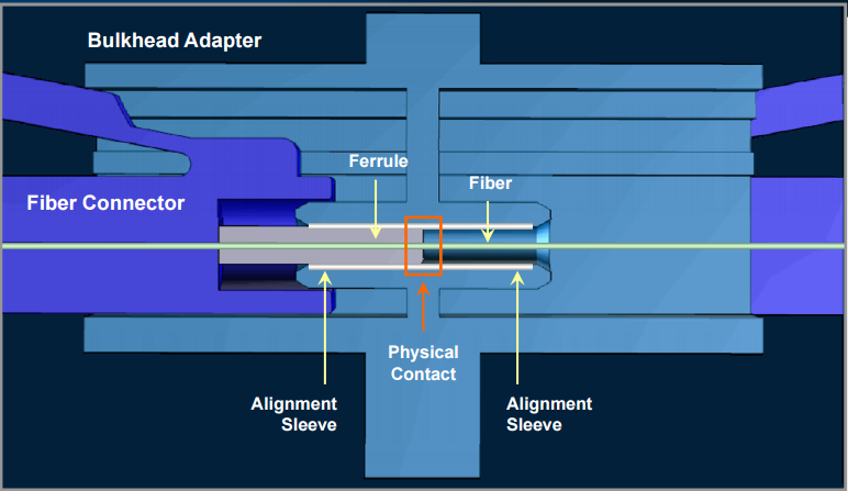
Cleaning consideration is a crucial issue in fiber optic cable technology today. If not cleaned properly, the ferrule in connectors is easy to be damaged when connecting, which can result in high costs. What’s more, it’s known to us that the fiber ferrules in the connectors make physical contact with another within the connectors alignment sleeve. Any contamination or dirt on one of the ferrules can easily be transferred to the mating ferrule, which can cause physical damage to the fiber’s end-face and further lead to information transmission failures. Hence, fiber optic connectors should be cleaned carefully.

fiber-optic-connector

How to Clean Fiber Optic Connectors?

Generally, there are two ways to clean fiber optic connectors. One is dry cleaning, and another is wet cleaning. Following is a brief introduction.

Usually, dry cleaning is to use a reel-based cassette cleaner to wipe the connector end-face against a dry cleaning cloth in one direction. For APC (angled physical contact) polished connectors, it’s essential to ensure the end-face surface mates with the cleaning cloth. Generally, dry cleaning can remove airborne contamination.

As for wet cleaning, first wipe the end-face against the wet area and then onto a dry area to clean potential residue from the end-face. Wet cleaning is more aggressive than dry cleaning, and can remove both airborne contamination and light oil residue.

What Types of Fiber Optic Cleaners Are There?

With more and more fiber optic components widely used, fiber optic cleaning is required for an optimum connection between both active fiber equipment and passive fiber equipment. Without cleaning, your network performance and reliability can be influenced. Here recommends two common types of fiber optic cleaners.

One-Push Cleaner

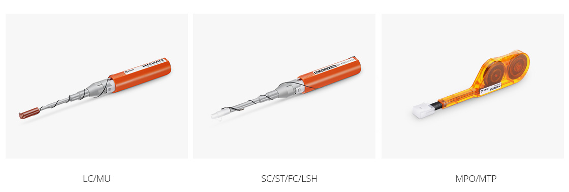
One-push cleaner is designed to clean male connectors, female bulkhead adapters, fiber patch cables and test equipment. It cleans the ferrule end-face by removing dust, oil and other contamination without scratching the end-face. FS provides several kinds of this cleaners such as one-push cleaner for LC/MU 1.25mm ferrules, one-push cleaner for SC/ST/FC/LSH 2.5mm ferrules, one-push cleaner for MTP/MPO connector and so on.

Pen cleaners

Fiber Optic Cassette Cleaner

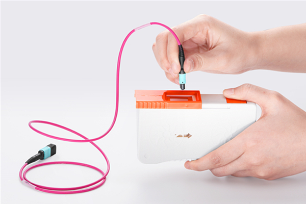
The cassette cleaner can wipe away contamination from optical connector end-face with ease. It’s very easy to use and suitable for LC/SC/FC/ST/MU/D4/DIN connectors. Usually, the body of this cleaner is made from antistatic materials which will not produce dust. And the common type of cassette cleaner is CLE-BOX fiber optic cassette cleaner.

cassette cleaner

What Should Be Noticed When Cleaning Fiber Optic Connectors?

There are various ways to clean fiber optic connectors. But we still should be careful when cleaning fiber optic connectors because they are easily damaged. Following are some helpful notes that should be given attention to when cleaning connectors.

  • Do not forget to inspect the fiber optic connector, component, or bulkhead before starting cleaning.
  • Do not allow the end of the fiber optic connectors to contact with any surface including fingers.
  • Do not use alcohol or wet cleaning if no residue left on the end-face. It can do harm to the equipment.
  • Do not push it with heavy pressure. Use the fiber optic cleaner correctly by inserting it at the correct angle and clean connectors carefully.
  • Do not forget to reinspect the connectors when cleaning has been finished.
Conclusion

Keeping fiber optic end-face clean is extremely important and one of the most critical requirements for ensuring accurate measurements and operation. Hence, choosing suitable cleaning tools for fiber optic connectors is significant. FS provides a number of fiber optic cleaning tools such as pen cleaner, cassette cleaner and so on. All this cleaning tools have good quality and high performance, which can make your fiber optic cleaning works easier and more convenient. Welcome to contact sales@fs.com.

How to Clean the Data Center?

Dust and dirt in data center could be a nightmare that troubles most of the telecom engineers. Now and then as they try to put their fingers on a distribution cabinet or a patch panel in a data center, the fingers are always stained by dust or dirt. However, this annoying situation is not rare for those engineers working in the field of telecommunication. Some of them may have realized the importance of cleanliness in data center, but they seldom take action to remove the dust and dirt. It means people simply attach less importance to keep the data center clean enough. Some contaminants can easily be seen or checked by eyes and hands, but there are still myriads of them existing inside the equipment which may lead to disastrous consequences such as overheating as well as various network failures if no proper action was taken to clean.

The Importance of Cleaning Data Center

Imagine what would happen if there is no regular cleaning in the data center? As it was mentioned above, the most direct result of contaminant is overheating. Since dust and pollutants in the data center are usually light-weight, If there is air flow, dust or dirt will move with it. The cooling system of the data center is depending largely on server fan which can bring the dust and dirt into the cooling system. The accumulation of these contaminant can cause fan failure or static discharge inside equipment. The heat dissipation will need more time and heat emission efficiency is limited. The following picture shows the contaminant at a server fan air intake that can explain this phenomenon.

the contaminant at a server fan air intake

As the cooling system is affected by the dust and dirt, the risk of the data center increases largely. Contaminants will capture every possible place in the data center where they are capable of. In addition, data center nowadays relies heavily on electronic equipment and fiber optic components like fiber optic connectors, which are very sensitive to contaminants. Problems like power failures, loss of data and short circuit might happen if the contaminants are not removed completely. What’s worse, short circuit might cause fire in the data center, which could lead to irreparable damage. The following picture shows the data center after a fire. It is really a disaster for the data center managers.

the data center after a fire

Dust and dirt can also influence the life span of data center equipment as well as their operation. The uptime of a data center may decrease if there are too many contaminants. Cleaning the data center regularly would help to reduce data center downtime and extend the life span of data center infrastructure equipment. It is proved to be cost efficient and energy saving comparing with restarting the data center or repairing the equipment.

Furthermore, data center cleanliness can offer an aesthetic appeal to a clean and dust-free environment. Although it is not the main purpose, a clean data center can present a more desirable working environment for telecom engineers, especially for those who need to install cable under a raised floor or working overhead racks and cabinet. No one would reject a cleaning data center.

Contaminants Sources of Data Center

There is no doubt that data center cleanliness is necessary. But how to keep the data center clean? Before taking action, source of contaminants in the data center should be taken into consideration. Generally, there are two main sources. One is inside the data center, and the other is from outside of the data center. The internal contaminants are usually particles from air conditioning unit fan belt wear, toner dust, packaging and construction materials, human hair and clothing as well as zinc whiskers from electroplated steel floor plates. The external sources of contamination include cars, electricity generation, sea salt, natural and artificial fibers, plant pollen and wind-blown dust.

Data Center Cleaning and Contaminants Prevention

Having known where the dust and dirt come from, here offers some suggestions and tips to reduce the contaminants.

  • Reduce the data center access. It is recommended that limited access to only necessary personnel can reduce the external contaminants.
  • Sticky mats should be used at the entrances to the raised floor, which can eliminate the contaminants from shoes largely.
  • Never unpack new equipment inside the data center, establish a staging area outside the data center for unpacking and assembling equipment.
  • No food, drink or smoking in the data center.
  • Typically all sites are required to have fresh air make-up to the data center, remember to replace on a regular basis.
  • Cleaning frequency depends on activity in the data center. Floor vacuuming should be more often as the traffic in the data center increased.
  • Inspect and clean the fiber optic components regularly, especially for fiber optic connector and interface of switches and transceivers.
  • The inside and outside of racks and cabinets should be cleaned.

Conclusion

Data center operates like an information factory nowadays as it processes countless data and information as well. Therefore, the cleanliness of the data center becomes increasingly important. If this essential “factory” is polluted by dust and dirt, it will eventually fail to provide reliable and qualified services. Not to mention that a clean data center could ensure a much more extended life span of equipment and applications thus to effectively save a great amount of money for the maintenance.

Things You Should Know about Fiber Optic Connector Polishing

Optical fiber is utilized for high-speed and error-free data transmission across connector assemblies. So the connector end faces need to be polished to optimize performance. And also the connectors must follow acceptance criteria related to insertion and back reflection loss as well as end-face geometry specifications. This article will talk about the fiber optic connectors polishing.

Polishing Process

Early physical contact connectors required spherical forming of their flat end faces as part of the polishing procedure. It involved a four-step process: epoxy removal, ferrule forming, and preliminary and final polishing. These steps utilized aggressive materials for epoxy removal and ferrule forming, generally accomplished with diamond polishing films. Now the polishing process has developed into a sequence of epoxy removal, followed by rough, intermediate and final polishing cycles because almost all connectors are manufactured with a pre-radiused end face. One goal is to avoid excessive disruption of the spherical surface, while still producing a good mating surface.

Polishing Specifications

Polishing specifications for fiber connectors fall into two categories related to performance and end-face geometry. Back reflection and insertion loss specifications are the most critical measures of polished end functionality. The insertion loss is the amount of optical power lost at the interface between the connectors caused by fiber misalignment, separation between connections (the air gap) and the finish quality of each connector end. The current standard loss specification is less than 0.5 dB, but less than 0.3 dB is increasingly specified. Back reflection is the light reflected back through the fiber toward the source. High back reflection can translate to signal distortion and, therefore, bit errors in systems with high data transfer rates.

Polishing Material

Today several types of connectorized fibers are available, the most common of which are 2.5 mm, 1.25 mm and multifiber. Connector end faces must first be air-polished to ensure a proper mating surface. This will be followed by a sequence of polishing steps depending on the type of connector, the back reflection and the insertion loss specifications. Regardless of the connector type, most polishing sequences begin with aggressive materials, including silicon carbide to remove epoxy and diamond lapping films for beginning and intermediate polishing. These remove both surrounding material and fiber at the same rate. But the last polishing step needs a less aggressive material to attack only the fiber, such as silicon dioxide. Using a material for final polishing that is too aggressive could result in excessive undercut. The wrong final-polish material can cause excessive protrusion, leading to fiber chipping and cracking during the connector mating process.

Impact Factor

Issues to be examined include the polishing films used, the type of epoxy and lubrication. Films are the most significant impact because the gradations and quality vary from supplier to supplier. End users should pay attention on selecting film type. Excessively aggressive films can destroy a 125-μm fiber and the end-face radius. Epoxy removal is also essential to contamination-free polishing. Some types of epoxies can be removed more easily with specific grades of silicon-carbide polishing films. The films to use in this step depend on the size of the epoxy bead mounted on the connector end face and the epoxy type. Epoxies have different varieties. Some will be tacky, some firm. In all, a contamination-free environment is essential to optimizing connector polishing.

Polishing may be an old art form, but for the immediate future, it’s here to stay. Undoubtedly inspection criteria will increase. Polishing procedures will be driven to change, and new connector style will also make us continuously strive to reinvent our approach to polishing. Fiberstore has various products about fiber optic polishing. For more details, please visit FS.COM.

Fiber Optic Access Network Will Be The Main Force Of Internet Information Highway In The Future

As with the rapid development of social information, fiber optic technology and devices which are dedicated to provide transfer of a new business for WAN and fiber optic access network. Developments of MSTP and PON are the most representative. They are also the best solution to provide various new business in the MAN and fiber optic access network which are based on fiber optic transmission technology. As water to the fish, the developments of fiber optic access technology can not without the support and development of fiber optic access devices.

Due to the constantly updated fiber optic access technology and more and more manufacturers’ accession, nowadays the fiber optic access devices categories are more and more obvious, mainly divided into three categories:

  • Fiber optic connection elements, it is applied into telecommunications and computer network terminal connections, related product: Fiber optic patch cable, fiber optic connector and so on.
  • Fiber optic transceiver, it is utilized for computer network data transmission, related products: Fiber optic splitter, fiber patch panels and so on.
  • Fiber optic engineer devices and fiber optic testers, it is specially for large-scale project, related products: Fiber optic fusion splicer, fiber optic testers.

Next we will introduce these three fiber optic access devices with a representative products respectively, they are fiber patch cables, fiber optic splitter, fiber optic fusion splicer.

Fiber optic patch cable (shown as the figure)is fiber optic cable or fiber optical unit which without fiber optic connector, it is used in fiber distribution frames on various link roads. Fiber patch cables are also used in long distance local optical network, data transmission and private network, various testing and control system.

Fiber optic splitter (shown as the figure), someone calls it as fiber coupler, it belongs to optical passive components, it is used in the telecommunications networks, fiber cable television networks, subscriber loop system. Fiber optic splitters can be divided into standard coupler (double branch, unit 1 x 2, that is, the light signal into two power, for example, 1×2 fiber optic splitter, 1 x4 fiber optic splitter, 1 x 8 fiber optic splitter and so on), star/tree fiber splitters and wavelength division multiplexer (WDM, if the wavelength is a high-density separation and wavelength spacing is narrow, it belongs DWDM).

Fiber optic fusion splicer(shown as the figure) is mainly used in telecommunication for fiber optic cables construction and maintenance, it is applied into telecommunication operators, engineering companies, private network, also used in the production of optical passive and active devices and fiber optical modules for fiber splicing.

All above the fiber optic access devices highly improve the data transmission and processing capabilities of fiber optic access network, and at the same time they can bring two advantages:

First, it solved the long distance transmission problems of fiber line attachment,and made its coverage range more widely. In this way, then it can reduce the number of transit nodes through whole the coverage network, make the structure of the network easier.

Second, it satisfied people’s needs to various broadband business, and improve the quality of new business data. It solved the problem of traditional copper cable access network fundamentally and laid a good foundation for achieving the dream of FTTH. I believe that in the future, fiber optic access network will be the main force of internet information highway.

New Application of Fiber Optic Connector Assembly at the Scene

Recent years, PON technology has been more widely used in the fiber optic industry because of its advantages on building cost, protection cost and the broad width. And in China, the three major telecom operators – China telecom, China unicom and China mobile all bring the EPON and GPON into the telecommunication network, at the same time, in order to support the application of PON technology, ODN network is built strongly, then it put forward higher requirements to fiber optic connection, protection as well as the application and management of fiber cable devices, the most obvious device among them is fiber optic patch cable.

We all know that tradition fiber patch cables are made to follow as the certain length of fiber optic connector assembly process, different lengths of fiber cables and connectors composed of a wide variety of fiber patch cords, they can be used in fiber optic patch panels, fiber transfer boxes, fiber cable devices and the connection between the devices and other optical ports, but just because these different fiber patch cables, it bring heavy pressure to storage management. Except this, traditional factory custom the length of fiber patch cables usually more than the actual length if the route and it leaves the length of the excess in a small disk space, we can see from the figure that not only it adds the cost of distribution frame and other cable devices but also not easy to manage, and too longer fiber cables always happens intertwined, knotted squeeze and circumstances, then result in unnecessary trouble, increase the cost of maintenance and management.

longer cable

Therefore, how to control the length of fiber patch cables effectively, to avoid all the trouble. To solve the problem, Fiberstore makes his opinion. we use the on site assembly of fiber connectors, and on the 2 mm or 3 mm fiber pigtail?into end and make fiber patch cable at the scene, replacing the traditional custom factory fiber patch cables, it can greatly alleviate the traditional fiber patch cables left too long, difficulties of managements, frequent failure those a series of maintenance problems. Fiberstore comes with the close communication with all the operators and joint efforts, apply the fiber optic connector assembly of FTTH at the secne into fiber patch cables managements of fiber equipments.

After the constant experiments and used for many time successfully, we have to believe that the embedded optical fiber types of fiber optical connector assembly at the scene will be the first choice for the fiber distribution frame, cable box, optical distribution boxes and other cable device in the future, it also can give ODN network cabling system maintenance and management to bring a revolutionary change.

Tutorial- How To Assemble a Fiber Optic Connector

Because there are many different types of fiber optic connectors have been developed, we will talk about fiber optic connectors in fairly general terms.

Most popular connectors in use today have some common elements. Let’s examine it below:

The most critical part, fiber is installed, is the ferrule. Ferrule is long, thin cylinder with the fiber mounted in the center hole. The size of the center hole is set to match the cladding of the fiber is usually 125 microns in diameter.

Fiber connector ferrules are made from several types of materials including ceramic (Zirconia), stainless steel and plastic.

The ferrule’s work is the center and align the fiber and protects it from mechanical damage. Finally at the end of the fiber ring and fiber end is polished smooth either flat or curvature.

The ferrule is mounted in the connector body and then the connector body is attached to the fiber optical cable structure. Finally, a strain-relief rubber boot protects the connector cable junction.

Unlike most electronic connectors, fiber optic connectors usually do not have the male-female polarity. Most fiber connectors are male only. Instead, fiber optic connectors to mate in the fiber optic adapter, it is often referred to as mating sleeves or coupling socket. Fiber optic adapter connector types used in different partners such as FC SC connector connector is called hybrid adapters.

Although this method needs to use a separate adapter, fiber optic connector it otherwise to reduce inventory requirements because now you only need to stock a type connector. Another advantage is that fiber optic adapters can be designed to mate one type of connector to another, which is a big plus compared to electronic connectors.

The fiber’s plastic coating is stripped first before the fiber is inserted in the ferrule. The center hole through the ferrule is large enough to fit the fiber cladding (which is usually 125um after fiber coating stripped off) but tight enough to hold the fiber in a fixed position without any further moving.

Standard bore diameters are 126 +1/-0 um for single mode connectors and 127 +2/-0 um for multimode connectors. Because of fiber cladding diameter’s variation from manufacturing, some fiber connector manufacturers also supply a range of ferrule bore sizes such as 124um, 125um, 126um and 127um.

Fiber optic epoxy or adhesive is inkected into the ferrule hole before the fiber is pushed in to hold the fiber in place. The epoxy or adhesive is then cured with high temperature oven according to adhesive manufacturer’s instruction. Finally the fiber end is polished to a smooth face on polishing films.

The ferrule is then slipped inside another hollow cylinder before it is mounted in the connector body. The connector body includes one or more pieces that are assembled to hold the cable and fiber in place. Connector body is made of metal or plastic.

The ferrule end protrudes beyond the connector body so it can slip into the mating sleeves (fiber adapters). A stain relief rubber boot is finally slipped over the cable end of the connector to protect the cable connector junction point.

In fiber optical cross connect boxes or fiber patch panels, an array of connector adpators are mounted inside, ready for you to plug an input fiber cable in one side and an output cable in the other. Fiber connector adapters are also mounted in wall outlets, just like standard phone jacket.

Corning’s Indoor Fiber Cables for Enterprise Networks

Corning cable system (also known as CCS) provides a very complete optic fiber cable product line for enterprise networks. Enterprise fiber network market includes universities, businesses, medical compuses, and more. Application types very a lot from indoor to outdoor. So let’s dive into the types of fiber cables Corning provides in this market.

Corning’s Indoor Fiber Cables for Enterprise Networks

Indoor Ribbon Fiber Cable

Corning’s Ribbon Fiber Optic Cables are designed for use in plenum, riser and general purpose environments for instrabuilding backbone installations and for high-fiber-count data centers. These cables consist of 2 to 216 fibers organized into 12 fiber ribbons inside a central tube. Dielectric strength members provide tensile strength while a specially formulated flame-retardant jacket allows the design to meet the requirements of the NFPA 262 flame test.

Indoor Loose Tube Fiber Cable

Corning’s MIC 250 cables utilize 250um color-coded optical fibers, surrounded by dielectric strength members with a flexible, flameretardant outer jacket. These cables are well suited for creating multi-fiber preconnectorized assembly as 12 fibers groupings enable compatibility with multi fiber optic connector. The flexible, flame retardant jacket and non-preferential bend axis allows installation in space-constrained areas and the all dielectric cable construction requires no grounding or bonding. These cables come in 62.5um, 50um and single mode versions, including Gigabit Ethernet and 10 Gigabit Ethernet versions.

Indoor Tight Buffered Fiber Cable

Corning’s MIC Riser Cables are designed for use in riser and general purpose environments for intrabuilding backbone and horizontal installations. These multi-fiber cables use 900um TBII buffered fibers which makes easy, consistent stripping and facilitate termination. This cable has a dielectric central member, the fibers are surrounded by dielectric strength members and protected by a flame-retardant outer jacket. The all- dielectric cable construction requires no grounding or bonding, making these cables ideal for routing inside buildings including riser shafts, to the telecommunications rooms and workstations.

Indoor Interconnect

Corning’s Zipcord Riser Cables are designed for interconnect applications. Two 900 um tight buffered fibers are surrounded by aramid yarn dielectric strength members and a flame-retardant jacket. This cable design offers mechanical durability and flame resistance that meets UL-1666 requirements for riser and general building applications. This cable also meets requirements of the National Electric Code (NEC) Article 770 and the cables are OFNR and CSA FT-4 listed.

Source: www.fs.com

Fiber Transmission Communication Network – Optical Terminal Box

Optical Fiber Termination Box in short OTB, optical terminal box is mainly used for the cable ends fixed, cable and pigtail splice and the remainder fiber asylum and protection. The communication network of fiber optic transmission optical cable terminal box series terminal wiring of auxiliary equipment, suitable for indoor fiber optic cable directly and branching connection of the fiber optic connector play a protective role.

The Material Performance

Optical cable terminal box where the parts are made of materials should have anti-corrosion properties, such as corrosion resistance should be treated with preservatives; Its physical and chemical properties must be stable; must be compatible between the various materials.

And sheath compatible with the cable jacket and wiring pigtail. In order to prevent corrosion and other electrical damage, these materials must also be compatible with other commonly used materials in the device.

Appearance of cable terminal box should be completer shape, no glitches, no bubbles, no cracks and voids, meta-warping element impurities and other defects. All background color shold be uniform and continuous. Beautiful appearance, convenient construction connecting additional attenuation reasonable structure, the fiber to strengthen the core fixed in the terminal box, cable metal outer sheath connected ground wire leads function applies to both the ribbon cable and fiber optic cable. Unique design, the terminal box on the 19-inch, wall-mounted terminal box.

Cable terminal box of the optical properties of the remaining fiber is coiled in the set fibers and optical fiber and fiber optic connectors, fiber optic terminal box installation of the operating additional attenuation.

Mechanical properties after the following tests, the cable terminal box box body and box should change, if necessary, for the fiber-ray examination.

1.Stretch: cable terminal box with a fiber optic cable should be able to withstand the axial tensile strength of not less than 500N, with either a wiring pigtail can withstand axial tensile strength of not less than 5N.
2. Flattening: The cable terminal box on each side of the box body should be able to withstand the vertical static pressure of not less than 200N.
3. Torsion: cable terminal box should be able to withstand the torsion angle.

Electrical performance

1. Insulation resistance: Cable connector box of metal components and optical metal reinforcing core fiber optic cable between the metal components, the insulation resistance between the cable metal parts and ground should not be less than 2 * 104MΩ [test voltage of 500V (DC).

2. Dielectric strength: cable terminal box with cable metal strengthening core fiber optic cable between the metal components, cable metal structures between the role of 15KV DC 1min, no breakdown, no flashover.

Optical Performance

The remaining fiber cable terminal box is coiled within the splice tray fiber and fiber optic connectors, cable terminal box installation of the operating there should be no additional attenuation.

Function

The splice closure is two pieces of fiber optic cable connection. The terminal box is the tip of the cable access, and then through the patch cord access optical switch. Therefore, the terminal box is usually installed in the 19-inch rack can accommodate fiber optic cable ends quantity more. The splice closure is two pieces of fiber optic cable connection. Terminal box is connected to the fiber optic cable with pigtail play a protective role. Indoor terminal box can be used for practical work with but very little splice closure when the terminal box uses not the same. 1. the transfer box can be divided into the cable transfer box and cable boxes. Their role in the user front-end wiring use. 2. Breakout boxes generally refers to the splice box, also known as fiber optic splice closure in some places, especially radio and television system, also known as optical splice pack, its role is to protect the cable connector does not damage by the outside world. Patch panel fiber optic patch panels and cable distribution frame, the role like the transfer case, but it is used in the engine room of the operators.

Application

Optical cable terminal box as a carrier of information transmission, fiber optic hardware as an information transmission medium, has become an important pillar of modern communication. optical cable terminal box technology from theory to the field of engineering technology experienced a few decades, to the realization of today’s high-speed fiber-optic communications, before and after the birth of the fiber-optic communications technology and in-depth development of information and communication in the history of an important reform.

Optical cable terminal box is widely used in telephone, if farmers network systems, data, image transmission system, CATV cable TV series for indoor fiber optic cable through power connection and branch connection, play a pigtail disc storage and protection of joint role, made of cold-rolled steel plate electrostatic spray, design, reasonable structure, appearance before a large fiber to strengthen the core fixed in the terminal.

Integrated Cabling Fiber Optic Cable Line Installation

Because, this period of communication network household cable lines, part of the outdoor, part of indoors, requirements and their way of laying optical fiber cables new requirements. These places the fiber capacity requirements will continue to grow, but still rules to follow, everything will depend on the needs of users. To have potential demand forecast puts the fiber optic cable, obviously will produce waste and the backlog of funds.

The same time, this section of optical fiber cable line communication network home will have to go through the route, may have stereotypes of the park, in this re-construction of large-scale
communication pipeline would be difficult, a large number of aerial installation will not only destroy the beautiful landscape, the line is not safe.

To resolve these needs problem, has to adapt to the new way of laying the products come out.

At present, domestic and foreign new fiber optic cable laying methods are mainly three categories: the first is Air blow installed micro-optic cable or optical fiber bundles, fiber unit blowing into the pre-laying micro tube; second is open on the cement pavement slot, micro cable laying on the road tank; the third is use of non-communication pipe installation cable.

Air blow installation with cable

Air blow laying methods using compressed air high-speed air micro-cable blown into the pipe specified. A blower the laying methods with a variety of superoprity. High-speed airflow, mini-cables in suspension in the pipeline, so the terrain changes and pipe bending the cable; improve fiber packing density can take advantage of the tubes and micro cable, save pipeline resources;

The eary simply laying the appropriate capacity fiber optic cable, after expansion in phases according to the development needs of a fiber optic sub-tubes blown into the main pipe has been built in batches, saving the initial launch, to avoid a large number of fiber idle; fiber optic cable can be increased at any time based on business needs branch, Y-fiber optic connector to reduce fiber optic cable connector.

Blowing installed with fiber optic cable, fiber optic cable is cloth on the sub-pipe systems and micro-pipeline designed. Sealed miniature fiber optic cable and indoor and outdoor non-metallic dual-use micro-optic cable.

Sealed miniature fiber optic cable

It uses fiber loose tube stainless steel tube structure, in addition to the general characteristics of a miniature cable diameter is small, light weight, but also has excellent high temperature properties and lateral pressure resistance. Stainless steel tube using laser welded stainless steel band, fiber and fiber paste it sealed inside, accurate excess length control technology to ensure the use of fiber optic cable in a complex environment.

And stainless steel pipe with excellent moisture resistance and physical rodent control, termite performance and acid resistance, fiber can give the best protection, to minimize the damage to fiber optic cable blowing mounting seal micro-optic cable.

Indoor and outdoor dual-use non-metallic fiber optic cable

Fiber optic cable terminal and maintenance and overhaul mostly be located in the street, the center room of the district, inside buildings or communications equipment. These places there are fire safety, must comply with special needs: self-extinguishing cable products, non-smoking, non-metallic dual-use, indoor and outdoor fiber optic cable, LSOH material mostly used.

Pavement micro-groove fiber optic cable

Pavement micro-groove fiber optic cable and air-blown fiber optic cable has a similar structure, but also a small cable diameter, the weight light fiber optic cable, and low cost, easy laying, laying flexible, simple and efficient. China’s development of a stainless steel loose tube technology-based pavement micro-groove fiber optic cable, fiber count up to 48 cores, outer diameter less than 6.0mm cable weight less than 60kg/km.

Wherein, stainless steel tube, both the protective tube of the optical fiber loose tube, able to provide the appropriate fiber excess length of fiber optic cable gland for completely isolated from the outside moisture from entering the casing, but also a reinforcing member of the fiber optic cable, by selecting the appropriate pipe cross-sectionalto ensure that the tensile properties of the fiber optic cable and flattening performance. Stainless steel tube filled with a thixotropic water blocking compound to ensure that the cable complies the seepage performance requirements, steel pipe is extruded polyethylene sheath.

Road microchannel cable laying only need to open a narrow slot in the road, covered with a layer of sand at the bottom, a buffer layer of foam rods and other material laid on the sand, then the fiber optic cable buried in the tank, and then the cableholes and a layer buffer layer, and finally fill in the cement or bitumen according to road conditions, restore the original road can be.

In the gardens, lawns, slotting in the garden or lawn, then sets of fiber optic cable with PVC pipe shop in the above, and then backfill can restore the surface. Pavement micro-groove fiber optic cable is very simple solution to the problem of the construction and deployment of FTTH across the concrete floor, indoor and outdoor garden lawn terrain.

Drainage Pipeline laying fiber optic cable

At present, China has developed and widely used in a stainless steel loose tube technology, rainwater pipes using the layer stranded wire for reinforcement member mini-cables, fiber core up to 48 cores, outside diameter less than 9.6mm, cable weight of less than 190kg/ km.

Stainless steel pipe in the fiber optic cable is both loose tube fiber protection tube, fiber optic cable gland, in the sewer environment can be completely cut off from the outside water and moisture from entering the casing. Steel casing to faciliate the provision of sufficient and stable fiber excess length, which is particularly important to ensure the fiber life of the self-supporting fiber optic cable attenuation temperature characteristics. Stainless steel tube filled with a thixotropic water blocking compound to ensure that the requirements of the cable complies seepage performance.

This drainage pipeline the laying of fiber optic cable, with the urban underground drainage pipeline to laying fiber optic cable. Installed drain pipe in the wall of the manhole placement of the fixed metal member, rainwater pipes on both ends of the cable surface with stainless steel hanging gold, the gold with a lock in the borehole will then be hanging on the fixing metal member, so that the cable tensioner, sag decreases, the suspension was self-supporting.

Cable laying on the drainage pipeline on the wall, in essence, the ends of the pipes in the manhole self-supporting, hanging, thus requiring Simple structure, light weight, small diameter cable, container density, and has a largetensile strength and flexibility characteristics.

In addition, the cable laying on the drainage channel environment, but also requires moisture resistance and good corrosion resistance, and has some rodent resistance ability.

Source: fiberstore.com

The Core Components of The Fiber Optic Connector: Ceramic Ferrule

What is ceramic ferrule? As the name suggests, the main material of the ceramic ferrule is ceramics, however, thia is not just ceramic so simple. Ceramic ferrules must be used in fiber optic communication, it is to ensure the communication quality is a very important role.

We all know that fiber connection technology is divided into two categories, one class is permanently connected, often called fixed joints dead joints; another class activities removable connection, often referred to as the union, need to use fiber optic connector. In the transmission network, a fiber optic cable connection between the permanent connection, the optical fiber connector is mainly used to implement the system between devices, between the equipment and instruments, equipment and between the optical fibers and the optical fibers and optical fiber between nonpermanent the fixed connection, it is the optical communication system of the most widespread and the largest use of basic passive devices. Matching ceramic material with quartz fiber thermal, physical and chemical properties and stability, as the core device with ceramic ferrule fiber optic connectors has been developed rapidly.

The most important role of the ceramic ferrule fiber physical docking (also known as fiber cold splice), often used in conjunction with ceramic sleeve, Ceramic cylindrical tube fired zirconia ceramic ferrule, hard texture, delicate white color accuracy of the finished sub-micron level, is the most commonly used in optical fiber communication network, the largest number of precision positioning pieces, often used for the manufacture of the optical connector, the optical coupling of the devices, and the like.

Like the ciruit in the plug and receptacle, the ferrule and sleeve are the key components of fiber optic connector. The diameter of only 0.125mm optical fiber must pass through the inner bore of the ceramic ferrule, and to maintain a linear transmissin of the state; connected to the outgoing optical fiber in the other end of the ceramic ferrule. Straight and precise connection directly affect the transmission efficiency of the optical fiber. Ceramic ferrule is not only highly internal hole diameter, while the outer diameter and concentricity requirements higher. And the optical connector because of the need for multiple plug, after repeated use must maintain the same accuracy of the same, very high demands on the material density.

The ceramic ferrule classification and features

Ceramic ferrule in accordance Dimensions is divided into three categories of SC, LC, and non-standard, in accordance with its precision, can be divided into two kinds of single-mode and multimode. The industry is often referred to as SC singlemode ferrule SC multimode ferrule LC singlemode ferrule LC multimode ferrule non-standard ferrule.

The ceramic ferrule characteristics depend on the characteristics of the material zirconia, mainly reflected in the good thermal stability, high hardness, high melting point, and wear-resistant, high machining accuracy.

Source: www.fs.com