Optical Amplifier Used in CATV Transmission Network

CATV technology has matured steadily over the past several years, and has expanded into diverse applications. However, as the quick expansion in technology and services, it’s important to improve CATV network component performance for higher visual and audio signals transmission. Optical amplifier for CATV application is the key element in such transmission. This post intends to give a clear introduction of optical CATV amplifier and its application in CATV transmission.

Introduction to CATV Amplifier

CATV amplifier is also a type of EDFA (Erbium Doped Fiber Amplifier) amplifier which is the most popular optical amplifier in optical network communications. It is mainly used to amplify damped TV signals (compensation for loss) for improved signal quality before sending them to each subscriber. Moreover, CATV amplifiers not only amplify the signal, but also amplify the noise on the line, and bring some return loss. That’s why a quality CATV amplifier price is a little high, because it can provide better performance for the whole network transmission.

Why CATV Amplifier Is Needed?

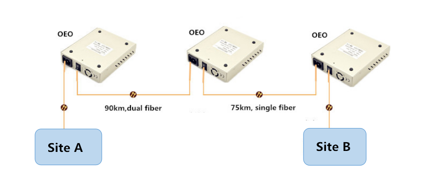
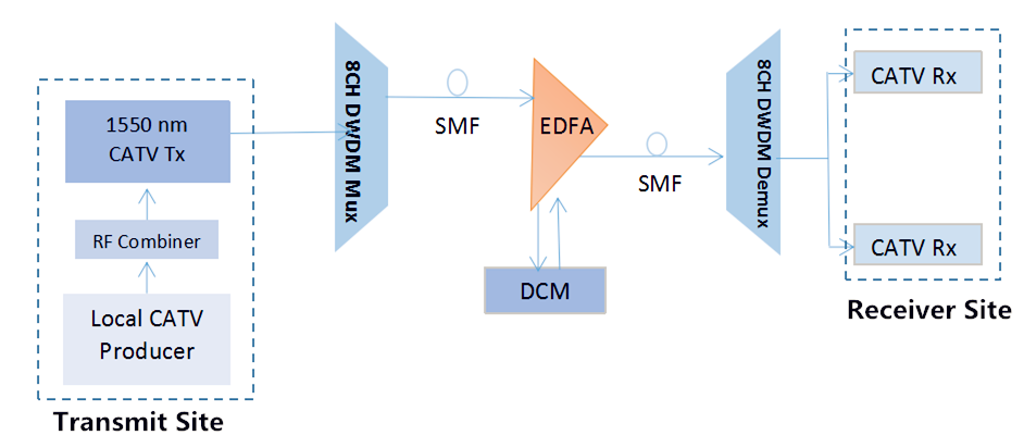
As we all know, CATV network is a multi-channel TV system to transmit high quality video and sound signal from a large number of digital or analog broadcast television and radio channel via fiber optic cable or coaxial cable. CATV amplifier often acts as booster optical amplifier in this system to get satisfying transmission effect. The following picture illustrates a basic long haul CATV transmission system using EDFA amplifier.

catv amplifier 1

In most cases, the satellite providers deliver high quality digital video and audio to users’ home depending on the users’ equipment. However, the signal incoming cable feed is connected to more than one equipment with use of optical splitters. And if the incoming signal gets fragmented and rerouted, the overall speed and quality will be worse. Under this condition, an optical amplifier can be used to boost the signal power and help users get better services.

CATV Amplifier in Long-Haul CATV Transmission System

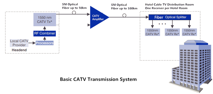
As have mentioned above, a basic long-haul CATV communication link consists of head end, transmitter, receiver, optical amplifier, and sometimes fiber splitter is also needed in this type of transmission network. The head end receives TV signals off the air or from satellite feeds, and supplies them to the transmission system. The optical splitters are often utilized in a poin-to-multipoint configuration. Here are two CATV fiber network cases using CATV booster amplifier.

Case one

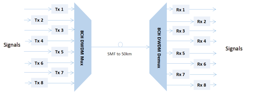
This is a point-to-multipoint medium size private CATV network. In the head end, the transmitter receives signals from the RF combiner on the 1310nm or 1550nm wavelength. Then the signals split into several parts and are received by the CATV receiver. Finally, all the signals are amplified by the CATV amplifier and sent to the subscriber.

catv amplifier 2

Case two

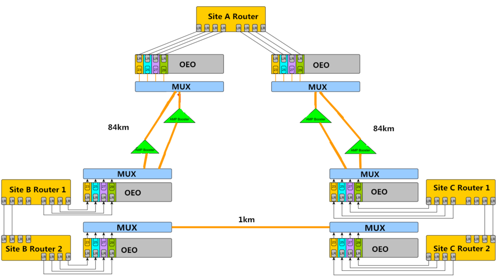
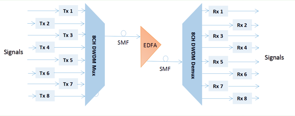
In the above application case, the optical amplifier lies behind the CATV receiver, but in this case, it’s a little different.

catv amplifier 3

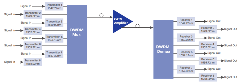
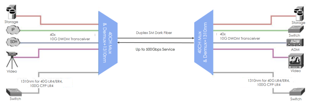
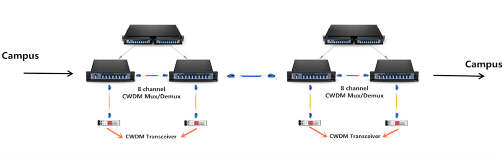
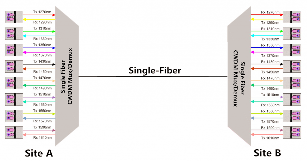
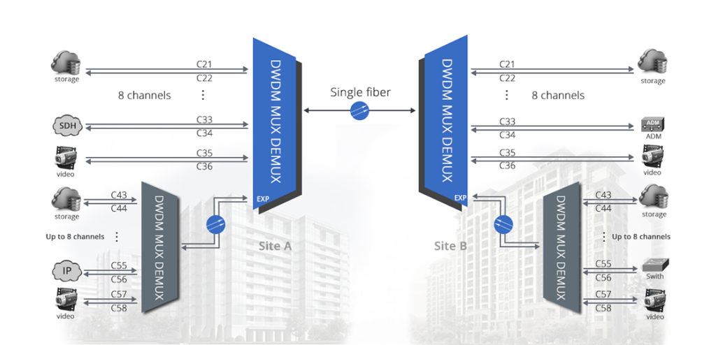
As we can see from the graph, the CATV amplifier lies in the front of the receiver to boost the transmission distance longer. Except for that, this transmission network also deploys two DWDM Mux/Demux to multiply the eight different wavelengths into one fiber for better transmitting. Please note that this graph just illustrates part of the long-haul CATV system.

Conclusion

CATV amplifiers are used to boost the quality of optical signals and improve the speed and reliability of the services that users get. FS.COM offers various CATV amplifiers with different values and CATV optical transmitter. All of them are high quality. If you are interested, please contact us via sales@fs.com.

Understanding WDM MUX/DEMUX Ports and Its Application

Wavelength division multiplexing (WDM) is a commonly used technology in optical communications. It combines multiple wavelengths to transmit signals on a single fiber. To realize this process, CWDM and DWDM mux/demux are the essential part. As we all know, there are several different ports on the WDM mux and demux. This article will give a clear explanation to these ports and their applications in WDM network.

Overview of Different Ports on WDM MUX/DEMUX
Line Port

Line port, sometimes also called as common port, is the one of the must-have ports on CWDM and DWDM Mux/Demux. The outside fibers are connected to the Mux/Demux unit through this port, and they are often marked as Tx and Rx. All the WDM channels are multiplexed and demultiplexed over this port.

Channel Port

Like the line port, channel ports are another must-have ports. They transmit and receive signals on specific WDM wavelengths. CWDM Mux/Demux supports up to 18 channels from 1270nm to 1610nm with a channel space of 20nm. While DWDM Mux/Demux uses wavelengths from 1470nm to 1625nm usually with channel space of 0.8nm (100GHz) or 0.4nm (50GHz). Services or circuits can be added in any order to the Mux/Demux unit.

40ch dwdm mux demux

Monitor Port

Monitor port on CWDM and DWDM Mux/Demux offers a way to test the dB level of the signal without service interruption, which enable users the ability to monitor and troubleshoot networks. If the Mux/Demux is a sing-fiber unit, the monitor port also should be a simplex one, and vice verse.

Expansion Port

Expansion port on WDM Mux/Demux is used to add or expand more wavelengths or channels to the network. By using this port, network managers can increase the network capacity easily by connecting the expansion port with the line port of another Mux/Demux supporting different wavelengths. However, not every WDM Mux/Demux has an expansion port.

dwdm mux demux

1310nm and 1550nm Port

1310nm and 1550nm are one of WDM wavelengths. Many optical transceivers, especially the CWDM and DWDM SFP/SFP+ transceiver, support long runs transmission over these two wavelengths. By connecting with the same wavelength optical transceivers, these two ports can be used to add 1310nm or 1550nm wavelengths into existing WDM networks.

Application Cases of Different Ports on WDM MUX/DEMUX

Although there are several different ports on WDM Mux/Demux, not all of them are used at the same time. Here are some examples of these functioning ports in different connections.

Example One: Using 8 Channels CWDM Mux/Demux with Monitor Port

cwdm mux demux with monitor port

This example is a typical point-to-point network where two switches/routers are connected over CWDM wavelength 1511nm. The CWDM Mux/Demux used has a monitor port and 1310nm port, but the 1310nm does not put into use. In addition, an optical power meter is used to monitor the power on fibers connecting the site A and B.

Example Two: Achieve 500Gbps at Existing Fiber Network with 1310nm Port

dwdm mux with 1310nm port

In this example, two 40 channels DWDM Mux/Demux with monitor port and 1310nm port are used to achieve total 500Gbps services. How to achieve this? First, plug a 1310nm 40G or 100G fiber optical transceiver into the terminal equipment, then use the patch cable to connect it to the existing DWDM network via the 1310nm port on the DWDM Mux/Demux. Since the 1310nm port is combined into a 40 channels DWDM Mux, then this set-up allows the transport of up to 40x10Gbps plus 100Gbpx over one fiber pair, which is total 500Gbps. If use 1550nm port, then the transceiver should be available on the wavelength of 1550nm.

Example Three: Stack Two CWDM MUX/DEMUX Using Expansion Port

cwdm mux with expansion port

The connection in this example is similar to the last one. The difference is that this connection is achieved with expansion port not 1310nm port. On the left side in the cases, a 8 channels CWDM Mux/Demux and a 4 channels CWDM Mux/Demux are stacked via the expansion port on the latter Mux/Demux. And the two 4 channels CWDM Mux/Demux are combined with the line port. If there is a need, more Mux/Demux modules can be added to increase the wavelengths and expand network capacity.

Summary

Different ports on the CWDM and DWDM Mux/Demux have different functions. Knowing more their function is helpful in WDM network deployment. FS.COM supplies various types of CWDM and DWDM Mux/Demux for your preference. And customer services are also available. If you have any needs, welcome to visit our website www.fs.com.

Application Cases of 10G CWDM Network

CWDM network, as an easy-to-deploy and cost-effective solution, has been applied in many areas. Although CWDM network is not as perfect as DWDM networks in data capacity, it still can satisfy a wide range of applications in optical applications. And CWDM is a passive network, allowing any protocol to be transported over the link, as long as it is at the specific wavelength. This article is going to describe several application cases of 10G CWDM network in different areas.

Benefits of 10G CWDM Network

Although 40G and 100G networks are developing rapidly, many of them still need to grow on the basis of 10G networks. And due to the high cost of 40G and 100G, 10G networks are still the most common networks to be deployed. Here are the main benefits of 10G CWDM networks.

  • CWDM Mux/Demux is a passive component and requires no extra power, offering a cost-effective choice for network designers.
  • Increased network connections and easy to evolve from 10G to 40G and 100G networks. For example, 10G CWDM network can combine DWDM wavelengths using the 1550nm channel on CWDM Mux/Demux. And if an operator want to upgrade its 10G network to 40G or 100G, there are various fiber components in market that can help him realize this conversion.
  • Lower cost. 10G hardware has become cheaper, which make 10G CWDM network more economical. For example, buying one pcs 8 channels CWDM Mux/Demux which is the most often used in CWDM networks needs less than 330 dollars in some stores. And 10G CWDM optical transceivers are also very cheap now.
10G CWDM Network Infrastructure

As has mentioned above, 10G CWDM network has been widely deployed in different areas. Here are the common CWDM network infrastructures.

Point-to-point 10G CWDM Network

A point-to-point CWDM network is the simplest network structure of CWDM networks, but it is the basis of other complex network infrastructures. By adding other components like CWDM OADM, the point-to-point CWDM network is easy to be changed into more complicated networks. The following figure shows a point-to-point CWDM network using 8 channels CWDM Mux/Demux.

point-to-point CWDM

10G CWDM Ring Network

CWDM ring links are suitable for interconnecting geographically dispersed LANs and storage area networks. Business can benefit from CWDM by using multiple Gigabit Ethernet. As shown in the below picture, the four buildings are connected by several 8 channels CWDM Mux/Demuxes.

CWDM ring network

Application Cases of 10G CWDM Network
Applications in Service Providers

CWDM uses different wavelengths to carry different signals over a single optical fiber, which offers many benefits to service providers that need to better utilize the existing fiber infrastructure. In this application, two Cisco switches are connected together through four 8 channels CWDM Mux/Demuxes. Signals are multiplexed and then transmitted through two strands fiber cables.

CWDM network

10G CWDM Application in Campus Network

As the scale expansion of many campus, the need for adding bandwidth of new applications is increasing too. And the new campus, school teaching and student life Internet require a lot of bandwidth resources, so building a new network is undoubtedly needs a large investment. Then how to make a full use of existing fibers is a problem needed to be resolved.

CWDM in campus

In this case, four 8 channels CWDM Mux/Demux with expansion port are used to double the capacity on the existing fiber without the need for installing or leasing additional fibers, which reduce cost and labor.

Summary

As the development of WDM technology and market, the deployment of CWDM network will be more lower. FS.COM provides affordable CWDM network components at a low price. Following is a list of our products.

Product ID Description
42945 8 channels 1290-1430nm dual fiber CWDM Mux Demux
43099 8 channels 1470-1610nm dual fiber CWDM Mux Demux with expansion port
19367 Cisco Compatible 10G CWDM SFP+ 1470nm 80km DOM Transceiver
31290 Cisco Compatible 10G CWDM SFP+ 1290nm 40km DOM Transceiver

How to Calculate Power Budget and Link Distance in CWDM Network

By multiplexing separated wavelengths from multiple ports onto a single fiber in the network, coarse wavelength division multiplexing (CWDM) network increases fiber capacity at a low cost. And all the CWDM components are passive and do not need power, which requires lower investment than DWDM networks and make it popular. This article intends to explore how to calculate the power budget and link distance in CWDM network, offering more conveniences for your CWDM network deployment.

Understand Optical Power Budget in CWDM System

One important factor of network design, including various optical networks like DWDM and PON, is the optical power budget. Optical power budget is the amount of light available to make a fiber optic connection. The difference between the output power of the transmitter and the input power requirements of the receiver is referred to as the power budget. The power budget with various losses in an optical fiber, as shown in the picture below, is obtained by first determining the optical power emitted by the source, usually expressed in dBm, and subtracting the power (expressed in same units, e.g., dBm) required by the detector to achieve the design quality of performance (Receiver Sensitivity). Here is a common equation that can be used to calculate the power budget in a decided length fiber link.

Link Power Budget = Min Transmit Power – Min Receiver Sensitivity

optical power budget CWDM

Calculate Power Budget in CWDM Network

When designing a CWDM network, power budget is often used to determine the maximum distance that a link can support. The transmission power budget is the difference between the optical transmitter output power and the receiver sensitivity. In order to explain the calculation process clearly, all the equations will be given an example for illustrating.

Power Budget = Tx Power – Rx Sensitivity.

Example one. A -2 dBm optical transmitter and a -25 dBm receiver provide a total transmission power budget of 23 dB.

Power Budget = Tx Power – Rx Sensitivity = -2 dBm – (-25 dBm) = 23 dB

As we all know, in a CWDM system, CWDM Mux/Demux, CWDM OADM and other components are common. And each one of them will introduce loss once added into the CWDM system. For example, when using a CWDM OADM in CWDM network, the point where a channel is dropped, added, or passed will cause a loss of signal strength. Therefore, when calculating power budget for a CWDM link, all losses must be added together. As shown in the following equation.

Power Budget = Tx Power – Rx Sensitivity – Losses

Example two. Here is a link A shown as below. There are four CWDM Mux/Demuxes and two CWDM SFP transceivers in this link. The Mux/Demux #1 and Mux/Demux #4 are 8-channel CWDM Mux/Demux. The left two is 4-channel CWDM Mux/Demux. Link A is the distance from CWDM SFP #1 and CWDM SFP#4. Each CWDM Mux/Demux has a low insertion loss. For instance, the insertion loss of the 8-channel CWDM Mux/Demux is less than 3.1dB (including connectors and adapters).

CWDM network

Here is the calculating process.

Power Budget = Tx Power – Rx Sensitivity – Losses

Tx Power = 2 dBm

Rx Sensitivity = -23 dBm

Losses = (8-channel Mux/Demux #1 loss) + (4-channel Mux/Demux #2 loss) + (4-channel Mux/Demux #3 loss) + (8-channel Mux/Demux #4 loss)

= 2.5 dB + 2.0 dB + 2.0 dB + 2.5 dB = 9.0 dB

Power Budget = Tx Power – Rx Sensitivity – Losses = 2 dBm – (-23 dBm) – 9.0 dB = 16 dB

Calculate Maximum Link Distance in CWDM Network

After determining the power budget for a fiber link, we can use the value to calculate the maximum distance that the link can support. The calculation equation is shown as below.

Power Budget = Buffer Distance/Fiber Attenuation

Usually, a buffer of 2 dB is subtracted from the power budget to account for other factors that may affect the loss of transmission power. These factors include fiber aging, temperature, poor splice, etc. Fiber attenuation is the loss of signal strength as it travels through the fiber. The attenuation varies with the wavelength. Typical values are 0.2 to 0.35 dB/km.

Then we will calculate the maximum supported distance of link A in example two. Here we take the worst value for the fiber attenuation. The distance is:

Distance = (16 dB-2 dB)/0.35dB/km = 40km

The maximum supported distance of link A is 40km.

Summary

Knowing how to calculate the power budget and transmission distance can help engineers estimate the CWDM network deployment cost, and also can avoid some unnecessary problems in network design. This post gives a clear illustration to calculate them. Hope it would help you. In addition, FS.COM is a professional manufacturer and supplier of optical components. If you have any need, welcome to visit our website www.fs.com.

How to Expand Bandwidth in PON Network with CWDM Technology?

PON (passive optical network) is one of a common optical fiber network architectures. It is characterized by the “splitting” of the optical fiber one or more times, resulting in the sharing of optical fiber among multiple users. However, as networks grow in terms of subscriber counts, the scope and number of services offered, expanding the network bandwidth is inevitable. Coarse Wave Division Multiplexing (CWDM), known for its low cost and scalability to increase fiber capacity as needed, is a preferred method for PON network expansion. This article will focus on using CWDM technology to overcome bandwidth limitations in PON access networks.

CWDM Mux/Demux and OADM (Optical Add-Drop Multiplexer) in Access PON

Fibers in a PON are typically shared with several users. Hence the bandwidth of the fiber originating at the CO (center office) is shared among a group of users. The splitting of the network is accomplished by optical splitters. These splitters can split the fiber 2-32 times, which may introduce high losses in the network. Besides, as different places in a same network need different wavelengths, CWDM Mux is often deployed to multiplex these signals on a single fiber.

In PON (Passive Optical Network) network, whether in ring structures or point-to-point arrangements, different optical nodes need specific wavelengths. Therefore, at each node, a CWDM OADM is used to drop or add certain channels from the fiber as required,. Then the signals will be transmitted to the user through optical fibers. The following picture shows a simple PON network.

PON

How to Expand Bandwidth of PON Network Using CWDM Technology?
Upgrading Access PONs Using Passive CWDM Mux/Demux

In PON networks, OLT has two float directions: upstream (getting an distributing different type of data and voice traffic from users) and downstream (getting data, voice and video traffic from metro network or from a long-haul network and send it to all ONT modules on the ODN).

The following figure represents a situation where existing subscribers intend to upgrade to higher value added bandwidth services. In order to satisfy customers’ needs for IPTV, VoIP, video on demand etc., the 622 Mb/s downstream capacity between the CO and the OLT, providing roughly 20 Mb/s to each subscriber, must increase.

PON network

Considering there may be new subscribers and services added, the targeted bandwidth requires at least a downstream CO/OLT link bandwidth of 2.5Gb/s. Therefore, four CWDM wavelengths are introduced to multiply the channels passing between the CO and OLT. This introduction of passive CWDM Mux/Demux can relieve the fiber exhaust effectively. The below figure shows the upgrading process.

PON upgrade

Advantages of This Upgrade

Compared with laying a new fiber cable, the upgrade with passive CWDM is easily accomplished within hours after some modest investment in network planning. And the sum of material, labor, equipment and training expense is far less, which explain why many enterprises, private business users of LAN and data storage networks use passive CWDM too.

Expanding EPON Bandwidth Using CWDM Mux/Demux

EPON stands for Ethernet passive optical network. It is an enabling technology that benefits consumers. Here is an EPON network, which was conceived to serve up to 64 subscribers. All users share a single bidirectional optical feed line. With the need for IPTV, HDTV and other higher bandwidth services growing, the downstream capacity 16Mb/s should be improved.

EPON

The picture below shows the same EPON deployment upgraded to 4Gb/s bandwidth capacity.

EPON network

This upgrade uses 4 channels passive CWDM Mux/Demux to extend the whole network capacity, allowing the downstream capacity increase four times without affecting the upstream traffic.

Advantage of This Expansion

Using CWDM Mux/Demux effectively increases the network bandwidth capacity and reduces the cost. At the same time, it requires minimal modification of the existing infrastructure, which also saves labors.

Summary

CWDM technology offers significant benefits of low investment, minimal operating cost and very simple and straightforward upgrade planning and implementation. In addition, passive CWDM also provides scalability and network flexibility for network growth and bandwidth demands in the future. FS.COM supplies different channels of CWDM components. Welcome to contact us via sales@fs.com.

Related article:Examples of CWDM Network Deployment Solution

Examples of CWDM Network Deployment Solution

Based on the same concept of using multiple wavelengths of light on a single fiber, CWDM and DWDM are two important technologies in fiber optical communications. As we all know, although the transmission distance of CWDM network is shorter than that of DWDM, it costs less and has the scalability to grow fiber capacity as needed. This article intends to give a simple introduction of components in CWDM networks and to explore some examples of CWDM network deployment cases.

Common Components Used in CWDM Networks
CWDM Mux/Demux

CWDM Mux/Demux, which is based on the film filter technology, is the basic component in CWDM networks. It can combine up to 4, 8 or 16 different wavelength signals from different fiber extenders to a single optical fiber, or it can separate the same wavelengths coming from a single CWDM source. That’s why CWDM can extend existing fiber capacity.

CWDM OADM (Optical Add-Drop Multiplexer)

A CWDM OADM is a device that can add (multiplex) and drop (demultiplex) channels on both directions in a CWDM network. It can add new access points anywhere in CWDM systems without impacting the remaining channels traversing the network. With this ability of OADM, the access points can be added to liner, bus, and ring networks, where the dual direction ring design provides redundant protected architecture.

CWDM Optical Transceiver

Optical transceiver is a necessary element in optical networks. And CWDM optical transceiver is a type of module supporting CWDM network application with CWDM wavelengths. When connected with CWDM Mux/Demux, CWDM transceiver can increase network capacity by allowing different data channels to use separate optical wavelengths (1270nm to 1610nm) on the same fiber. And the common CWDM transceiver type is SFP, SFP+, XFP, XENPAK, X2, etc.

CWDM Network Deployment Solution
Example One

Description: there are five buildings (Sheriff, Courthouse, Admin, Police & Fire, & Public Works) connected via multimode fiber cables (MMF) or single mode fiber cables (SMF). These buildings are linked via multimode SFPs in an existing D-link switches to create one network for internal use of the city offices. Below is a simple graph to show the situation.

CWDM Network 1

Requirements: the goal is to install a single mode fiber network in town to connect numerous buildings. Some of these buildings have access to the city LAN. The Public Works building need to connect with Youth & Recreation Center, Library, Immanuel Lutheran School and the Senior Center. And all these buildings should have unfiltered Internet. Besides, the Waster Water Treatment Plant should be connected passing through the Senior Center. All these services are achieved using CWDM technology.

Solution: according to the requirements, this is a CWDM networks with several buildings to connect with. Here is the solution diagram.

CWDM Network

In the diagram above, we can see there is an 8CH CWDM Mux/Demux connected with the switches. According to the requirements, Youth & Recreation Center, Library, Immanuel Lutheran School and Senior Citizen Center should be connected with the Public Works and need unfiltered services. Therefore, a 4CH CWDM OADM is placed after the CWDM Mux/Demux. Then the four wavelengths will be drop and into the four buildings. In addition, another CWDM OADM is deployed in Senior center to connect the Waster Water Treatment Plant, to meet the requirement. And each site also needs to use CWDM optical transceivers.

Example Two

Description: on site A, there are three Ethernet switches and a T3 router. And their working wavelengths 1470nm, 1490nm, 1510nm, 1530nm and 1610nm. Other three sites B, C, and D also have three Ethernet switches. And a T3 router is in site E. As the following figure shows.

CWDM OADM

Requirements: Considering the cost, all the wavelengths should be transmitted on a single fiber using CWDM technology.

Solution: according to the requirements, here is a simple diagram showing the solution.

CWDM Mux Demux

In order to save cost, a 4CH CWDM Mux/Demux is used to multiplex four wavelengths (from three switches and one router) into one single fiber. At the first site B, a 1CH CWDM OADM is installed to remove one wavelength which is associated with network B. And other three sites are the same—dropping one wavelength associated with corresponding switch or router.

Summary

This article mainly introduces two CWDM network deployment examples. All the components like the CWDM Mux/Demux, CWDM OADM and CWDM transceiver are available in FS.COM. If you are interested in them, please contact us via sales@fs.com.

Related article:Differences between CWDM and DWDM

How to Realize Single Fiber Connection in WDM System?

As we all know, fiber optical networking has two transmission ways: dual fiber transmission and single fiber transmission. The difference between them is that the former one requires two fibers—one is for transmitting and the other is for receiving, while the latter only uses one fiber for both transmitting and receiving. Single fiber transmission emergence reduces network deployment cost, especially in WDM systems. This blog intends to introduce how to achieve single fiber connections in CWDM and DWDM networks.

Understanding Single Fiber Transmission

Single fiber transmission, also called bidirectional (BiDi) transmission, sends data in both directions with one strand fiber. For enterprise networks or telecom networks providers who are with limited budgets and fiber capacity, the single fiber transmission is no doubt an ideal choice.

In addition, single fiber transmission is popular in many places.

  • Point to Point, Ring or linear Add and Drop, where installing new fiber is difficult or expensive
  • Enable segmentation of the enterprise traffic over 2 different fibers rather than using the same fiber for both segments
  • Increase reliability to an existing dual fiber solution by using one fiber for working and one for protecting
Single Fiber Solution in CWDM Systems

CWDM technology enables multiple channels (wavelengths) to be transmitted over the same fiber cabling and is able to provide a capacity boost in metro and access networks. Each channel carries data independently from each other, which allows network providers to transport different data rates and protocols (T1, T3, Ethernet, Serial, etc) for different customers or applications. Then how to achieve single fiber transmission in CWDM networks?

Here is an example of single fiber solution in CWDM system.

8-ch-single-fiber-cwdm-mux-demux

The above picture shows how different CWDM wavelengths are transmitted in a single fiber CWDM link. In this link, two 8CH CWDM Mux/Demuxs are required to transmit sixteen different wavelengths. At site A, there is a single fiber 8CH CWDM Mux/Demux using eight wavelengths for transmitting and the other different eight wavelengths for receiving. At site B, another 8CH single fiber CWDM Mux/Demux is deployed. But the wavelengths for TX and RX are reversed. And one single fiber connects the two CWDM Mux/Demux.

Notes: the use of transceivers connected with the CWDM Mux/Demux should be based on the wavelength of the TX side.

Single Fiber Solution in DWDM Systems

DWDM is an optical multiplexing technology to increase bandwidth over existing fiber optic networks, especially in long haul transmissions. And it can support more channels and higher traffic services such as 40G, 100G of LAN/WAN. Since the cost of DWDM components is high, the single fiber transmission is necessary.

DWDM single fiber transmission can be achieved with the use of single fiber DWDM Mux/Demux. As the following picture shows.

DWDM single fiber solution

The picture shows a single fiber 8CH DWDM Mux/Demux with expansion port used for single fiber transmission. Similar to the single fiber CWDM Mux/Demux above, this DWDM Mux/Demux also uses eight wavelengths for transmitting and another eight wavelengths for receiving. In general, the DWDM Mux/Demux should be used in pairs in single fiber bi-directional transmission, and the Mux/Demux port for specific channel must be reversed. Besides, more channels can be added into the links with the expansion port.

This 8CH DWDM Mux/Demux single fiber solution allows extremely high utilizing of a single fiber strand to pass up to 16 wavelengths, optimizing the use of fiber optic cables. And in long distance transmission, optical amplifier also can be utilized.

FS.COM Single Fiber Solution

FS.COM supplies various single fiber CWDM & DWDM Mux/Demux and optical transceivers. Here is part of our Mux/Demux products.

Single Fiber CWDM & DWDM Mux/Demux Operating Channel
cwdm mux-demux Tx/Rx:1310/1290, 1350/1330, 1390/1370, 1430/1410, 1490/1470, 1530/1510, 1570/1550, 1610/1590
DWDM mux-demux Tx/Rx:C21/C22,C23/C24,C25/C26,C27/C28, C29/C30,C31/C32,C33/C34,C35/C36

Analysis of OEO Transponder Application in WDM Network

Anyone who has experiences of deploying WDM networks, either DWDM or CWDM networks, may be familiar with OEO transponder. Since in WDM network deployment, especially for long haul transmission, OEO transponder plays an important role. OEO transponder, also known as WDM transponder, means optical-to-electrical-to-optical. That is to say, it converts an optical signal to an electrical signal, and then recovers it to an optical signal. In some cases, OEO transponder serves as fiber mode converter or repeater for long distance transmission.

OEO transponders

Functions of OEO Transponder
Wavelength Conversion

As we all know, when add a CWDM Mux/Demux or DWDM Mux/Demux into a WDM network, there is a requirement to convert the optical wavelengths like 850nm, 1310nm and 1550nm to CWDM or DWDM wavelengths. Then the OEO transponder comes to assist. The OEO transponder receives, amplifies and re-transmits the signal on a different wavelength without changing the signal content.

Fiber Mode Conversion

It’s know to us that multimode fiber optic cables (MMF) are often used in short distance transmission, while single mode fiber optic cables (SMF) are applied in long optical transmission. Therefore, in some network deployment, considering the transmission distances, MMF to SMF or SMF to MMF conversions are needed.

Signal Repeating

In long haul fiber optic transmission, OEO transponder also can work as repeater to extend network distance by converting wavelengths (1310nm to 1550nm) and amplifying optical power. The OEO converter converts the weak optical signals from the fiber into electrical signals, and regenerates or amplifies, then recovers them into strong optical signals for continuous transmission.

Analysis of OEO Transponder Application Case

Having known about the function of OEO transponder, here let me take some application cases as examples to illustrate its applications clearly.

Case One

The distance between site A and site B is about 165km, and there is a repeater station C. The distance between A and C is 90km. The client needs to build connection between A and B. Just like the following picture shows.

OEO transponder

In this solution, three OEO transponders are used in this links according to the requirements of the client. The use of the first OEO converter at site A is to convert the signals from MMF to SMF, achieving the long distance transmission between site A and C. The second OEO transponder re-generates and amplifies the optical signal, then convert the it from dual fiber to single fiber. At site B, the OEO transponder re-amplifies the optical signal and recovers it to multimode transmission.

Advantages of this solution: use OEO transponder to achieve fiber mode conversion and long distance transmission; make full use of the OEO transponder (retime, regenerate and reshape) to realize high quality connections; save cost by using the OEO transponder.

Case Two

This solution is more complicated than the first one. There are three sites with fiber links between them. The distance between site A and B is 84km, and site B and C is 1km. Site A and C is 84km too. All the 10G connections are dual fiber transmission. Here is a simple picture of this solution.

OEO transponder application

As we can see in the figure, to build DWDM networks between these three sites, six OEO transponders are deployed. Each site uses two OEO transponders. The OEO transponder at site A converts the 10G-LR signals into 10G DWDM wavelengths, then the wavelengths are multiplexed by the DWDM Mux. At site B, the separated wavelengths are recovered to 10G-LR signals through the OEO transponder. The transmission between site B and C, site A and C are similar to the transmission between site A and B. In addition, there are two EDFAs in each two long distance transmissions.

Advantages of this solution: using OEO transponder for wavelength conversion. Converting common 10G signals into DWDM wavelengths and transmitting them with DWDM MUX/DEMUX increase the network capacity easily. At the same time, it also reduces the damage of optical transceivers.

Summary

OEO transponder is an important components in optical networks. This post gives a simple analysis of OEO transponder application case. Hope it’s useful for you. FS.COM supplies high quality 10G OEO converters like SFP+ to SPF+ and XFP to XFP, and 40G WDM transponder like QSFP+ to QSFP+. If you want to know more detailed information, please contact us via sales@fs.com.

How to Calculate DWDM System Loss in Long Haul Transmission

Nowadays, high capacity network is needed to deal with large amount of data transfer. The application of DWDM (dense wavelength division multiplexing) system is a commonly used technique to enhance network capacity. Due to its complexity caused by various components like EDFA and dispersion compensating module (DCM), it may be difficult to calculate the loss over the whole links, especially in long haul transmissions. Then, how to calculate the budget loss of a DWDM system in long haul transmission? This post will illustrate the method to solve this problem.

Causes of Loss in Long Haul DWDM System

Loss budget is always one of the crucial problems that need to be considered before deploying a network. Any components in optical links will introduce loss. For example, when add a DWDM mux to a DWDM network, it will cause insertion loss which is the total optical power loss (often measured by dB) caused by the insertion of an optical component. In long haul DWDM system, there are several causes of link loss.

DWDM Muxs

DWDM Muxs are the components that combine several different wavelengths so that they can be transferred on one fiber. And Mux is a passive device that cannot strengthen the light signals. Therefore, there is a big insertion loss of DWDM Mux. The lower the insertion loss is, the less network deployment cost is needed. Although Mux vendors are always endeavoring to reduce the insertion loss, there are still big differences between DWDM Muxs of many vendors. Here is a histogram to provide a direct-viewing comparison. From the graph, we can see the maximum insertion loss of FS.COM 40CH DWDM Mux is only 4.5dB.

40ch dwdm mux insertion loss comparison

DCM (Dispersion Compensation Module)

Dispersion compensation module is to fix the optical signals that have been deformed by chromatic dispersion. Therefore it is important to use at the receiver end to recover the signals by reshaping the optical pulse. This component also brings a good amount of insertion loss.

OADM (Optical Add/Drop Multiplexer)

OADM is another device that introduces insertion loss for DWDM networks. Since it allows individual or multiple wavelength channels to be added or dropped from an incoming link, as the signal pass from the common port to add/drop port or from the add/drop port to the common port, insertion loss occurs.

Except for the components that cause loss for the whole links, fiber optic cables also introduce loss which increases as the distance gets longer. Besides, in order to achieve balance signal power for receivers, designers often use EDFA to boost or add gain to optical signals on a fiber optic cable.

How to Calculate the Loss Budget of DWDM System?

In order to illustrate the calculation process clearly, here takes a case from FS.COM as an example. This deployment solution is designed for a client in UK. The following picture just shows part of the solution design.

40ch dwdm mux solution

The distance of site A and site B is 132.4km. From the figure, we can see optical components used includes 40CH DWDM Mux/Demux, booster EDFA, Pre-amplifier, 2CH OADM, etc. And there are also optical attenuators which are not shown in the figure. Here is a chart indicating the loss or gain value of them which can be found on FS.COM website.

Components Insertion loss/Gain
40CH DWDM+MON 4.5dB
Booster EDFA 23dB
Pre-amp EDFA 26dB
Attenuator 0-30dB

Now let’s start to calculate the budget loss in this link. Considering the whole solution is so complicated that this calculation is just to give an example of calculating the budget loss between site A and site B. And the calculation starts from site A to site B unidirectional, as the arrow line shows.

  • The loss between the 40CH DWDM Mux and the router is -8.5dB, caused by the use of an optical attenuator.
  • Then the signals pass through the DWDM Mux, the output power is:-8.5dB-4.5dB =-13dB.
  • Since the booster EDFA gain is +23dB, the signal output power of this EDFA is: -13dB+23dB= +10dB.
  • Calculation of the fiber optic cable, the total loss is: -0.22dB/km x132.4km = -29.13dB. The input power of the pre-amp EDFA is: +10dB-29.13dB = -19.13dB.
  • The pre-amp EDFA gain is +26dB, then the output power of this EDFA is +6.87dB.
  • There is an attenuator placed after the pre-amp EDFA, the output power after the attenuator is: +6.87dB-18dB = -11.13dB.
  • The output power of the booster EDFA is: +23dB-11.13dB=+10.67dB. That’s the output power of site B.
Summary

For DWDM network system, how to control the power loss is important, which requires network designers calculate the budget loss before deploying the systems. This post gives an example from our client to calculate the loss in a DWDM network. FS.COM offers both necessary optical components and solutions for your networks. If you are interested, please contact us via sales@fs.com.

Solutions to Achieve Long-haul Transmission With DWDM Systems

In order to increase the transmission distance of optical signals, many technologies, like the TDM (time division multiplexing) and WDM (wavelength division multiplexing), have been used. Except for that, several optical components like single mode fiber optic cables, optical amplifiers and dispersion compensating modules (DCMs) are also put into use to realize the goal. Today, this article intends to illustrate the solutions to achieve longer transmission distances with DWDM technology.

Solutions to Extend Transmission Distances

When it comes to long-haul optical transmissions, DWDM (dense wavelength division multiplexing) is a topic that cannot be ignored. DWDM technology enables different wavelengths to transmit over a single optical fiber. Different wavelengths are combined in a device—Mux/Demux which is short of multiplexer/demultiplexer. The DWDM Mux/Demux provides low insertion loss and low polarization-dependent loss for optical links. Here take a 8CH DWDM Mux/Demux for example to illustrate how to extend distance in long haul transmission.

Solution One

The first solution is suitable for applications that are less than 50km. The picture below shows a unidirectional application with 8CH DWDM Mux/Demux. As we can see, in this links, the DWDM Mux/Demux transmits 1550nm signal over one single mode fiber. The eight different signals from the transmitters are multiplexed into 1550nm signal by the 8CH DWDM Mux. Then they go through the single mode fiber and are separated into the original wavelengths by the DWDM Demux. The use of DWDM Mux/Demux and single mode fiber allows the system to transmit over 50km without optical amplifier or DCM.

8 channel mux demux in long haul transmission

Notes: this solution is the basic application of DWDM Mux/Demux in a relative long distance comparing to CWDM technology which suits short distance deployment.

Solution Two

Different from the first solution, if the link distance is longer than 50km, this solution can be taken into account. Optical signal loss will become greater as the links are getting longer, which means an optical amplifier module or dispersion compensator is needed. Therefore, to achieve a satisfying signal quality in long-distance transmission, an EDFA which can boost the weakened optical signals is added in this solution (as shown in the picture below).

edfa in long haul transimission

Solution Three

This DWDM configuration is similar to the former one, but with the EDFA, the link distance on the single mode fiber is up to 200km. However, sometimes an EDFA is not enough to achieve a quality signal, especially in some long haul systems like CATV system. Because these systems often have a high requirement for the quality of optical signal. Therefore, as we can see in the following picture, except for the DWDM Mux/Demux and EDFA, there is also a DCM.

edfa and dcm in long haul transmission

This solution is a point-to-multipoint long haul system deploying a DCM to extend the transmission distance. From the picture, the EDFA is placed midway between the transmitter and receiver in the transmission path. And in order to ensure the quality of the whole transmission, a DCM module is added in this link to deal with the accumulated chromatic dispersion without dropping and regenerating the wavelengths on the link.

Notes: all the three solutions are unidirectional transmission on single mode fiber cables. If a network requires bidirectional transmission to transfer eight signals, you can use a 16CH DWDM Mux/Demux over single fiber or a 8CH DWDM Mux/Demux over dual fiber.

Summary

WDM technology, especially the DWDM, is the critical step to go into the super-long distance transmission in optical communication. This post mainly introduces three basic solutions to realize long haul transmission with DWDM Mux/Demux. All the components including the DWDM Mux/Demux (both 8 channels and 16 channels), EDFA, DCM and optical modules are available in FS.COM. If you have any needs, please contact us via sales@fs.com.