Optical Amplifier Used in CATV Transmission Network

CATV technology has matured steadily over the past several years, and has expanded into diverse applications. However, as the quick expansion in technology and services, it’s important to improve CATV network component performance for higher visual and audio signals transmission. Optical amplifier for CATV application is the key element in such transmission. This post intends to give a clear introduction of optical CATV amplifier and its application in CATV transmission.

Introduction to CATV Amplifier

CATV amplifier is also a type of EDFA (Erbium Doped Fiber Amplifier) amplifier which is the most popular optical amplifier in optical network communications. It is mainly used to amplify damped TV signals (compensation for loss) for improved signal quality before sending them to each subscriber. Moreover, CATV amplifiers not only amplify the signal, but also amplify the noise on the line, and bring some return loss. That’s why a quality CATV amplifier price is a little high, because it can provide better performance for the whole network transmission.

Why CATV Amplifier Is Needed?

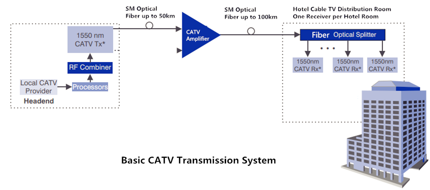
As we all know, CATV network is a multi-channel TV system to transmit high quality video and sound signal from a large number of digital or analog broadcast television and radio channel via fiber optic cable or coaxial cable. CATV amplifier often acts as booster optical amplifier in this system to get satisfying transmission effect. The following picture illustrates a basic long haul CATV transmission system using EDFA amplifier.
catv amplifier 1

In most cases, the satellite providers deliver high quality digital video and audio to users’ home depending on the users’ equipment. However, the signal incoming cable feed is connected to more than one equipment with use of optical splitters. And if the incoming signal gets fragmented and rerouted, the overall speed and quality will be worse. Under this condition, an optical amplifier can be used to boost the signal power and help users get better services.

CATV Amplifier in Long-Haul CATV Transmission System

As have mentioned above, a basic long-haul CATV communication link consists of head end, transmitter, receiver, optical amplifier, and sometimes fiber splitter is also needed in this type of transmission network. The head end receives TV signals off the air or from satellite feeds, and supplies them to the transmission system. The optical splitters are often utilized in a poin-to-multipoint configuration. Here are two CATV fiber network cases using CATV booster amplifier.

Case one

This is a point-to-multipoint medium size private CATV network. In the head end, the transmitter receives signals from the RF combiner on the 1310nm or 1550nm wavelength. Then the signals split into several parts and are received by the CATV receiver. Finally, all the signals are amplified by the CATV amplifier and sent to the subscriber.

catv amplifier 2

Case two

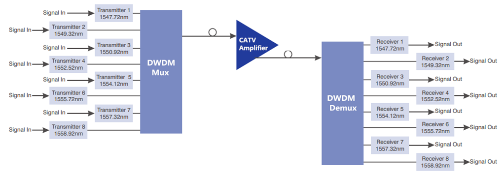
In the above application case, the optical amplifier lies behind the CATV receiver, but in this case, it’s a little different.
catv amplifier 3

As we can see from the graph, the CATV amplifier lies in the front of the receiver to boost the transmission distance longer. Except for that, this transmission network also deploys two DWDM Mux/Demux to multiply the eight different wavelengths into one fiber for better transmitting. Please note that this graph just illustrates part of the long-haul CATV system.

Conclusion

CATV amplifiers are used to boost the quality of optical signals and improve the speed and reliability of the services that users get. FS.COM offers various CATV amplifiers with different values and CATV optical transmitter. All of them are high quality. If you are interested, please contact us via sales@fs.com.

Introduction of EDFA

Before talking about Erbium-doped fiber amplifier (EDFA), we must have a simple understanding about optical amplifier (OA). OA is a device that amplifiers an optical signal directly, without the need to first convert it to an electrical signal. It is an important component in optical communication. There are usually 3 different types of OA, including erbium-doped fiber amplifier (EDFA), semiconductor optical amplifier (SOA) and Raman amplifier. EDFA is just one type of OA but plays an important role in a long-haul optical fiber communication. Now I’d like to make a detailed introduction of EDFA.

EDFA is an optical repeater device. It is usually used to improve the intensity of optical signals being carried through a fiber optical communication system. An optical fiber is doped with the rare earth element erbium so that the glass fiber could absorb light at one frequency and emit light at another frequency. With its features of high power transfer efficiency and large dynamic range, as well as low noise figure and polarization independent, it is an ideal solution for Wavelength Division Multiplex (WDM) applications and long-haul applications. In addition, a particular advantage of EDFA is its large gain bandwidth, which is typically tens of nanometers and thus actually more than enough to amplify data channels with the highest data rates.

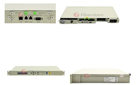
EDFA sample

Now let us learn the basic principle of EDFA. EDFA is a high gain amplifier. It usually has two used pumping bands 980nm and 1480nm. This action amplifies a weak optical signal to a higher power, effecting a boost in the signal strength. The 980nm band has a higher absorption cross-section and is generally used where low-noise performance is required. The absorption band is relatively narrow so that wavelength stabilised laser sources are typically needed. The 1480nm band has a lower, but broader, absorption cross-section and is generally used for higher power amplifiers. In practice, a combination of 980nm and 1480nm pumping bands is usually used in EDFA.

The following picture shows us the working principle of EDFA. In optical fiber communication system, a relatively high-powered beam of light is mixed with the input signal using a wavelength selective coupler. The input signal and the excitation light must be at different wavelengths. The mixed light is guided into a section of fiber with erbium ions included in the core. This high-powered light beam excites the erbium ions to their higher-energy state. When the photons belonging to the signal at a different wavelength from the pump light meet the excited erbium atoms, the erbium atoms give up some of their energy to the signal and return to their lower-energy state. A significant point is that the erbium gives up its energy in the form of additional photons which are exactly in the same phase and direction as the signal being amplified. So the signal is amplified along its direction of travel only. Thus, all of the additional signal power is guided in the same fiber mode as the incoming signal. There is usually an isolator placed at the output to prevent reflections returning from the attached fiber. Such reflections disrupt amplifier operation and in the extreme case can cause the amplifier to become a laser.

principle of EDFA

By this blog, we have learnt that what is EDFA and its basic principle. If you have any requirements, welcome to visit Fiberstore.com or contact us over sales@fiberstore.com. Fiberstore is a professional supplier in this field. It can offer EDFA for you with high quality and competitive price.

Micrel Launches New Limiting Post Amplifier for 10Gbps FTTH PON Network

Micrel Semiconductor has introduced SY88053CL and SY88063CL limiting post amplifier. Both devices support the expansion of the next generation passive optical network (PON) FTTH XGPON and 10GEPON optical line terminal (OLT) ideal for applications. The product line also applies to support multi-rate applications. Fiber optic transceiver module, the maximum rate is up to 12.5Gbps. Support for Ethernet, Fibre Channel, OTN and OBSAI data rate.
“These new devices offer an impressive number of features including a new level of high bandwidth, high input sensitivity with programmable, wide range SD Assert and LOS De-Assert threshold levels, 4dB of electrical hysteresis, and stable SD Assert and LOS De-Assert timing to meet the stringent requirements of next generation PON network,” stated Tom Kapucija,director of marketing for the high speed communications business, Micrel. “Thesse features enable link efficiency optimization with increased system reach, higher link up-time and higher payload bandwidth.”Vice president for the timing and communications business group, Rami Kanama, said, “As the demand for more data at higher speeds increases, carries need to meet this demand by upgrading their line-side equipment and revamping their networks. Micrel continues its effort in addressing this demand at the device level. Our new optical limiting amplifier delivers speed, performance, and features that is critical to solving technical difficulties facing next generation FTTH, Enterprise, and transport networks. With increased link efficiency, system operators can achieve higher data transmission performance and potentially reduce carries’ CapEx and OpEx.”
Both devices incorporate fast SD Assert and LOS De-Assert times across the entire differential input voltage range of 5mVPP to 1800mVPP which enables improved link efficiency and optimization. In 3mVPP to 30mVPP wide LOS / SD threshold range provides a 4dB electrical hysteresis.  Integrated 50 Ohm input and output impedances optimize high speed signal integrity while reducing external component counts and in turn, cost. TTL compatible JAM input enables a SQUELCH function by routing back the LOS or SD signal.
The SY88053CL enable user adjustable decision threshold adjustment for optimized Bit Erro Rate operation in noisy applications with asymmetrical noise distribution while the SY880563CL provides a user selectable Digital Offset Correction function that automatically compensates for internal device offsets in the high speed data path. Other features include multi-rate 1Gbps to 12.5Gpbs operations, optional LOS or SD output, selectable RXOUT +/ RXOUT- signal polarity (SY88053CL) and 25ps typical rise / fall time. Beyond the current customer demand through increased performance margins, improved manufacturability of the module, while reducing costs. By increasing each node and the downstream branch exceeds 512ns link budget margin established, to improve the efficiency and data throughput of the link. By optimizing in a noisy environment and the error rate or RAMAN EDFA Optical Amplifier noise characteristics of asymmetric compensation, expanding the system extends the scope to improve the data throughput.
Both devices offer a wide power supply range of 3.3V+/-10 percent and come in an industrial temperature range of -40 degC to +85-degC and a tiny 3mm x 3mm QFN package.
Source: www.fs.com/news/