How to Calculate DWDM System Loss in Long Haul Transmission

Nowadays, high capacity network is needed to deal with large amount of data transfer. The application of DWDM (dense wavelength division multiplexing) system is a commonly used technique to enhance network capacity. Due to its complexity caused by various components like EDFA and dispersion compensating module (DCM), it may be difficult to calculate the loss over the whole links, especially in long haul transmissions. Then, how to calculate the budget loss of a DWDM system in long haul transmission? This post will illustrate the method to solve this problem.

Causes of Loss in Long Haul DWDM System

Loss budget is always one of the crucial problems that need to be considered before deploying a network. Any components in optical links will introduce loss. For example, when add a DWDM mux to a DWDM network, it will cause insertion loss which is the total optical power loss (often measured by dB) caused by the insertion of an optical component. In long haul DWDM system, there are several causes of link loss.

DWDM Muxs

DWDM Muxs are the components that combine several different wavelengths so that they can be transferred on one fiber. And Mux is a passive device that cannot strengthen the light signals. Therefore, there is a big insertion loss of DWDM Mux. The lower the insertion loss is, the less network deployment cost is needed. Although Mux vendors are always endeavoring to reduce the insertion loss, there are still big differences between DWDM Muxs of many vendors. Here is a histogram to provide a direct-viewing comparison. From the graph, we can see the maximum insertion loss of FS.COM 40CH DWDM Mux is only 4.5dB.
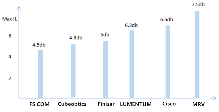
40ch dwdm mux insertion loss comparison

DCM (Dispersion Compensation Module)

Dispersion compensation module is to fix the optical signals that have been deformed by chromatic dispersion. Therefore it is important to use at the receiver end to recover the signals by reshaping the optical pulse. This component also brings a good amount of insertion loss.

OADM (Optical Add/Drop Multiplexer)

OADM is another device that introduces insertion loss for DWDM networks. Since it allows individual or multiple wavelength channels to be added or dropped from an incoming link, as the signal pass from the common port to add/drop port or from the add/drop port to the common port, insertion loss occurs.

Except for the components that cause loss for the whole links, fiber optic cables also introduce loss which increases as the distance gets longer. Besides, in order to achieve balance signal power for receivers, designers often use EDFA to boost or add gain to optical signals on a fiber optic cable.

How to Calculate the Loss Budget of DWDM System?

In order to illustrate the calculation process clearly, here takes a case from FS.COM as an example. This deployment solution is designed for a client in UK. The following picture just shows part of the solution design.
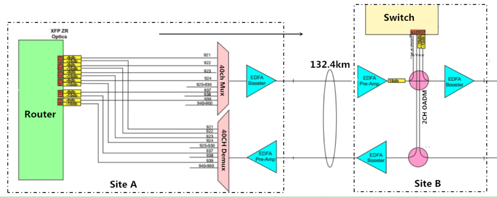
40ch dwdm mux solution

The distance of site A and site B is 132.4km. From the figure, we can see optical components used includes 40CH DWDM Mux/Demux, booster EDFA, Pre-amplifier, 2CH OADM, etc. And there are also optical attenuators which are not shown in the figure. Here is a chart indicating the loss or gain value of them which can be found on FS.COM website.

Components Insertion loss/Gain
40CH DWDM+MON 4.5dB
Booster EDFA 23dB
Pre-amp EDFA 26dB
Attenuator 0-30dB

Now let’s start to calculate the budget loss in this link. Considering the whole solution is so complicated that this calculation is just to give an example of calculating the budget loss between site A and site B. And the calculation starts from site A to site B unidirectional, as the arrow line shows.

  • The loss between the 40CH DWDM Mux and the router is -8.5dB, caused by the use of an optical attenuator.
  • Then the signals pass through the DWDM Mux, the output power is:-8.5dB-4.5dB =-13dB.
  • Since the booster EDFA gain is +23dB, the signal output power of this EDFA is: -13dB+23dB= +10dB.
  • Calculation of the fiber optic cable, the total loss is: -0.22dB/km x132.4km = -29.13dB. The input power of the pre-amp EDFA is: +10dB-29.13dB = -19.13dB.
  • The pre-amp EDFA gain is +26dB, then the output power of this EDFA is +6.87dB.
  • There is an attenuator placed after the pre-amp EDFA, the output power after the attenuator is: +6.87dB-18dB = -11.13dB.
  • The output power of the booster EDFA is: +23dB-11.13dB=+10.67dB. That’s the output power of site B.
Summary

For DWDM network system, how to control the power loss is important, which requires network designers calculate the budget loss before deploying the systems. This post gives an example from our client to calculate the loss in a DWDM network. FS.COM offers both necessary optical components and solutions for your networks. If you are interested, please contact us via sales@fs.com.

Solutions to Achieve Long-haul Transmission With DWDM Systems

In order to increase the transmission distance of optical signals, many technologies, like the TDM (time division multiplexing) and WDM (wavelength division multiplexing), have been used. Except for that, several optical components like single mode fiber optic cables, optical amplifiers and dispersion compensating modules (DCMs) are also put into use to realize the goal. Today, this article intends to illustrate the solutions to achieve longer transmission distances with DWDM technology.

Solutions to Extend Transmission Distances

When it comes to long-haul optical transmissions, DWDM (dense wavelength division multiplexing) is a topic that cannot be ignored. DWDM technology enables different wavelengths to transmit over a single optical fiber. Different wavelengths are combined in a device—Mux/Demux which is short of multiplexer/demultiplexer. The DWDM Mux/Demux provides low insertion loss and low polarization-dependent loss for optical links. Here take a 8CH DWDM Mux/Demux for example to illustrate how to extend distance in long haul transmission.

Solution One

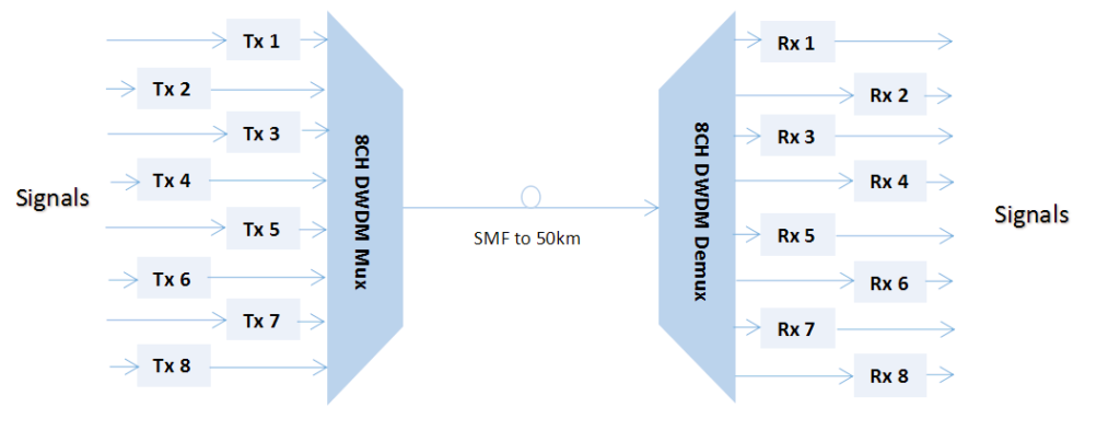
The first solution is suitable for applications that are less than 50km. The picture below shows a unidirectional application with 8CH DWDM Mux/Demux. As we can see, in this links, the DWDM Mux/Demux transmits 1550nm signal over one single mode fiber. The eight different signals from the transmitters are multiplexed into 1550nm signal by the 8CH DWDM Mux. Then they go through the single mode fiber and are separated into the original wavelengths by the DWDM Demux. The use of DWDM Mux/Demux and single mode fiber allows the system to transmit over 50km without optical amplifier or DCM.

8 channel mux demux in long haul transmission

Notes: this solution is the basic application of DWDM Mux/Demux in a relative long distance comparing to CWDM technology which suits short distance deployment.

Solution Two

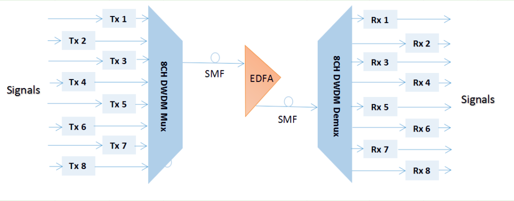
Different from the first solution, if the link distance is longer than 50km, this solution can be taken into account. Optical signal loss will become greater as the links are getting longer, which means an optical amplifier module or dispersion compensator is needed. Therefore, to achieve a satisfying signal quality in long-distance transmission, an EDFA which can boost the weakened optical signals is added in this solution (as shown in the picture below).

edfa in long haul transimission

Solution Three

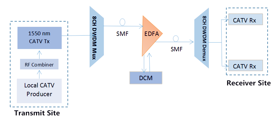
This DWDM configuration is similar to the former one, but with the EDFA, the link distance on the single mode fiber is up to 200km. However, sometimes an EDFA is not enough to achieve a quality signal, especially in some long haul systems like CATV system. Because these systems often have a high requirement for the quality of optical signal. Therefore, as we can see in the following picture, except for the DWDM Mux/Demux and EDFA, there is also a DCM.

edfa and dcm in long haul transmission

This solution is a point-to-multipoint long haul system deploying a DCM to extend the transmission distance. From the picture, the EDFA is placed midway between the transmitter and receiver in the transmission path. And in order to ensure the quality of the whole transmission, a DCM module is added in this link to deal with the accumulated chromatic dispersion without dropping and regenerating the wavelengths on the link.

Notes: all the three solutions are unidirectional transmission on single mode fiber cables. If a network requires bidirectional transmission to transfer eight signals, you can use a 16CH DWDM Mux/Demux over single fiber or a 8CH DWDM Mux/Demux over dual fiber.

Summary

WDM technology, especially the DWDM, is the critical step to go into the super-long distance transmission in optical communication. This post mainly introduces three basic solutions to realize long haul transmission with DWDM Mux/Demux. All the components including the DWDM Mux/Demux (both 8 channels and 16 channels), EDFA, DCM and optical modules are available in FS.COM. If you have any needs, please contact us via sales@fs.com.
Introduction of EDFA

Before talking about Erbium-doped fiber amplifier (EDFA), we must have a simple understanding about optical amplifier (OA). OA is a device that amplifiers an optical signal directly, without the need to first convert it to an electrical signal. It is an important component in optical communication. There are usually 3 different types of OA, including erbium-doped fiber amplifier (EDFA), semiconductor optical amplifier (SOA) and Raman amplifier. EDFA is just one type of OA but plays an important role in a long-haul optical fiber communication. Now I’d like to make a detailed introduction of EDFA.

EDFA is an optical repeater device. It is usually used to improve the intensity of optical signals being carried through a fiber optical communication system. An optical fiber is doped with the rare earth element erbium so that the glass fiber could absorb light at one frequency and emit light at another frequency. With its features of high power transfer efficiency and large dynamic range, as well as low noise figure and polarization independent, it is an ideal solution for Wavelength Division Multiplex (WDM) applications and long-haul applications. In addition, a particular advantage of EDFA is its large gain bandwidth, which is typically tens of nanometers and thus actually more than enough to amplify data channels with the highest data rates.

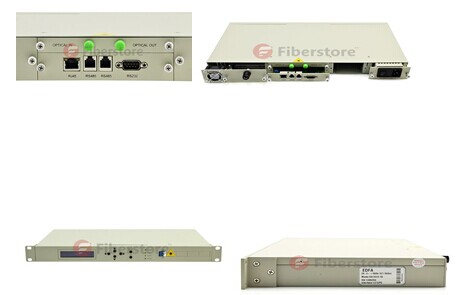
EDFA sample

Now let us learn the basic principle of EDFA. EDFA is a high gain amplifier. It usually has two used pumping bands 980nm and 1480nm. This action amplifies a weak optical signal to a higher power, effecting a boost in the signal strength. The 980nm band has a higher absorption cross-section and is generally used where low-noise performance is required. The absorption band is relatively narrow so that wavelength stabilised laser sources are typically needed. The 1480nm band has a lower, but broader, absorption cross-section and is generally used for higher power amplifiers. In practice, a combination of 980nm and 1480nm pumping bands is usually used in EDFA.

The following picture shows us the working principle of EDFA. In optical fiber communication system, a relatively high-powered beam of light is mixed with the input signal using a wavelength selective coupler. The input signal and the excitation light must be at different wavelengths. The mixed light is guided into a section of fiber with erbium ions included in the core. This high-powered light beam excites the erbium ions to their higher-energy state. When the photons belonging to the signal at a different wavelength from the pump light meet the excited erbium atoms, the erbium atoms give up some of their energy to the signal and return to their lower-energy state. A significant point is that the erbium gives up its energy in the form of additional photons which are exactly in the same phase and direction as the signal being amplified. So the signal is amplified along its direction of travel only. Thus, all of the additional signal power is guided in the same fiber mode as the incoming signal. There is usually an isolator placed at the output to prevent reflections returning from the attached fiber. Such reflections disrupt amplifier operation and in the extreme case can cause the amplifier to become a laser.

principle of EDFA

By this blog, we have learnt that what is EDFA and its basic principle. If you have any requirements, welcome to visit Fiberstore.com or contact us over sales@fiberstore.com. Fiberstore is a professional supplier in this field. It can offer EDFA for you with high quality and competitive price.