How to Calculate DWDM System Loss in Long Haul Transmission

Nowadays, high capacity network is needed to deal with large amount of data transfer. The application of DWDM (dense wavelength division multiplexing) system is a commonly used technique to enhance network capacity. Due to its complexity caused by various components like EDFA and dispersion compensating module (DCM), it may be difficult to calculate the loss over the whole links, especially in long haul transmissions. Then, how to calculate the budget loss of a DWDM system in long haul transmission? This post will illustrate the method to solve this problem.

Causes of Loss in Long Haul DWDM System

Loss budget is always one of the crucial problems that need to be considered before deploying a network. Any components in optical links will introduce loss. For example, when add a DWDM mux to a DWDM network, it will cause insertion loss which is the total optical power loss (often measured by dB) caused by the insertion of an optical component. In long haul DWDM system, there are several causes of link loss.

DWDM Muxs

DWDM Muxs are the components that combine several different wavelengths so that they can be transferred on one fiber. And Mux is a passive device that cannot strengthen the light signals. Therefore, there is a big insertion loss of DWDM Mux. The lower the insertion loss is, the less network deployment cost is needed. Although Mux vendors are always endeavoring to reduce the insertion loss, there are still big differences between DWDM Muxs of many vendors. Here is a histogram to provide a direct-viewing comparison. From the graph, we can see the maximum insertion loss of FS.COM 40CH DWDM Mux is only 4.5dB.
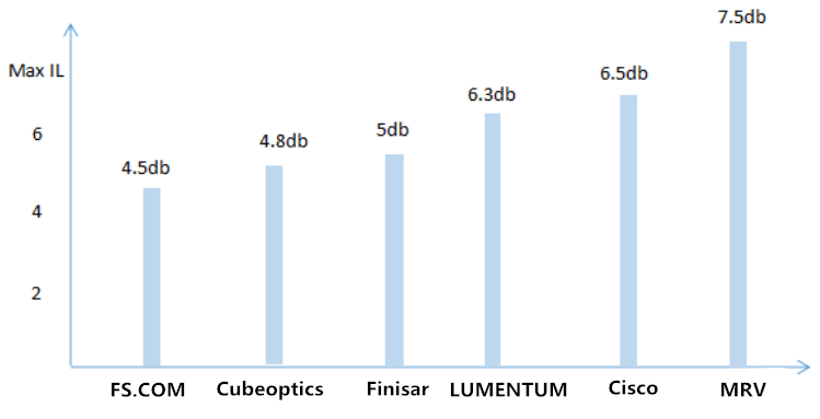
40ch dwdm mux insertion loss comparison

DCM (Dispersion Compensation Module)

Dispersion compensation module is to fix the optical signals that have been deformed by chromatic dispersion. Therefore it is important to use at the receiver end to recover the signals by reshaping the optical pulse. This component also brings a good amount of insertion loss.

OADM (Optical Add/Drop Multiplexer)

OADM is another device that introduces insertion loss for DWDM networks. Since it allows individual or multiple wavelength channels to be added or dropped from an incoming link, as the signal pass from the common port to add/drop port or from the add/drop port to the common port, insertion loss occurs.

Except for the components that cause loss for the whole links, fiber optic cables also introduce loss which increases as the distance gets longer. Besides, in order to achieve balance signal power for receivers, designers often use EDFA to boost or add gain to optical signals on a fiber optic cable.

How to Calculate the Loss Budget of DWDM System?

In order to illustrate the calculation process clearly, here takes a case from FS.COM as an example. This deployment solution is designed for a client in UK. The following picture just shows part of the solution design.
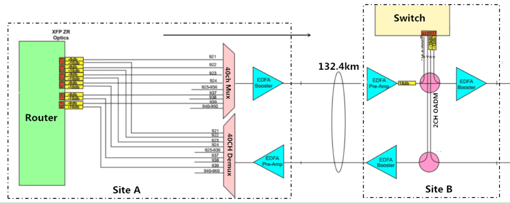
40ch dwdm mux solution

The distance of site A and site B is 132.4km. From the figure, we can see optical components used includes 40CH DWDM Mux/Demux, booster EDFA, Pre-amplifier, 2CH OADM, etc. And there are also optical attenuators which are not shown in the figure. Here is a chart indicating the loss or gain value of them which can be found on FS.COM website.

Components Insertion loss/Gain
40CH DWDM+MON 4.5dB
Booster EDFA 23dB
Pre-amp EDFA 26dB
Attenuator 0-30dB

Now let’s start to calculate the budget loss in this link. Considering the whole solution is so complicated that this calculation is just to give an example of calculating the budget loss between site A and site B. And the calculation starts from site A to site B unidirectional, as the arrow line shows.

  • The loss between the 40CH DWDM Mux and the router is -8.5dB, caused by the use of an optical attenuator.
  • Then the signals pass through the DWDM Mux, the output power is:-8.5dB-4.5dB =-13dB.
  • Since the booster EDFA gain is +23dB, the signal output power of this EDFA is: -13dB+23dB= +10dB.
  • Calculation of the fiber optic cable, the total loss is: -0.22dB/km x132.4km = -29.13dB. The input power of the pre-amp EDFA is: +10dB-29.13dB = -19.13dB.
  • The pre-amp EDFA gain is +26dB, then the output power of this EDFA is +6.87dB.
  • There is an attenuator placed after the pre-amp EDFA, the output power after the attenuator is: +6.87dB-18dB = -11.13dB.
  • The output power of the booster EDFA is: +23dB-11.13dB=+10.67dB. That’s the output power of site B.
Summary

For DWDM network system, how to control the power loss is important, which requires network designers calculate the budget loss before deploying the systems. This post gives an example from our client to calculate the loss in a DWDM network. FS.COM offers both necessary optical components and solutions for your networks. If you are interested, please contact us via sales@fs.com.

Optical Add-drop Multiplexer Overview

With an explosive growth in the amount of information transmission, the optical telecommunication networks develop rapidly. The progress of single wavelength point-to-point transmission lines to wavelength division multiplexed optical networks has introduced a demand for wavelength selective optical add-drop multiplexer (OADM) to separate or route different wavelength channels. This paper will have an overview of the OADM.

OADM Technology

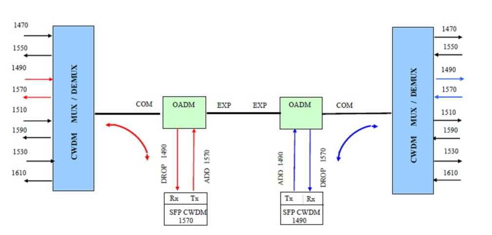
The introduction of optical add drop multiplexers into optical networks allows traffic to be inserted, removed and, most importantly, bypassed. Moreover, OADM can support functions such as protection, drop/continue, loop-back and wavelength reuse of the optical channels. Drop and continue refer that the channel is removed at the node but allowed to pass through to the next OADM. Wavelength reuse means the dropped channel does not pass through to the next OADM, instead, a new channel of the same wavelength can be added. Below figure explains OADMs work in a CWDM system.

CWDM OADM
Passive and Dynamic OADM

OADM can be used in the dynamic as well as static mode. The add and drop wavelengths are fixed in the passive OADM, while in dynamic mode, the OADM can be set to any wavelength after installation. Passive OADM is mainly used in networks with WDM systems (CWDM and DWDM) or hubbed structures, where the OADM is connected to a central hub, e.g. in the metropolitan network. In order to utilize resources in a more efficient way, the OADM with dynamic wavelength assignment are preferred when traffic variations are comparable to network capacity. It can select any wavelength by provisioning on demand without changing its physical configuration.

Advantages

OADM has many advantages. The most striking one is that its multiplexing happens to coincide with the minimum loss area of single mode fiber. This reduces the transmission loss of the light signal which can be transmitted relatively far distance. Additionally, it is transparent to digital signal format and data rate. Its gain saturation recovery time is long, and has a very small crosstalk between the respective channels. What’s more, multiple channels of information carried over the same fiber with each using an individual wavelength. Narrow channel spacing or wavelength selection give rise to denser channels in the same wavelength range. Last but not the least, repeater or amplification sites are reduced, which results in large savings of funding.

Applications

OADM supports standard network topologies such as point-to-point and ring. It can be used at different points along the optical link to insert/remove or route selected channels increasing the network flexibility. This feature is particularly important in metropolitan WDM lightwave services where offices or sites can be connected by different add-drop channels, for instance in an interoffice ring. In WDM systems, OADM is installed in a multi-wavelength fiber span, and allows a specific wavelength on the fiber to be demultiplexed (dropped) and remultiplexed (added) while enabling all other wavelengths to pass. Then it can provide flexibility and scalability to optical networks as it allows users to optimize the use of existing fiber by adding or dropping channels on a per-site basis, thereby maximizing fiber bandwidth.

In conclusion, optical add-drop multiplexer can contribute to improve and optimize the network performance. Fiberstore, a professional supplier in the optical industry, has lots of CWDM OADM and DWDM OADM. Besides these, the WDM fiber optic multiplexer, CWDM Mux/Demux and DWDM Mux are also available. Welcome to visit www.fs.com for more information.

Basic Knowledge about Optical Switch

Introduction of Optical Switch

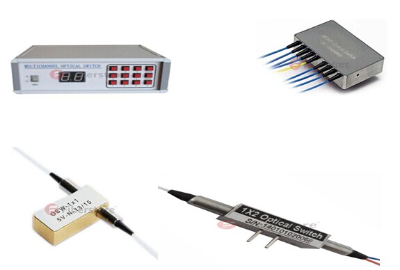
Optical switch is an optical device that enables signals to be selectively switched from one circuit to another in optical fibers or integrated optical circuits (IOCs). It is widely used in optical switching, configuration optical add/drop multiplexer(OADM), optical fiber ring protection and optical cross and connection system. It could be divided four types, opto-mechanical optical switch, MEMS optical switch, solid-state fiber optical switch and rackmount & benchtop optical switch. Optical switch is one of the main factors to affect the optical performance of the fiber network. It plays a very important role in the optical network.

optical switch types

Functionality of Optical Switch

The functionality of an optical switch can be described as an optical connection. A connection is the association between two ports on a switch and is indicated as a pair of port identifiers (i, j), where i and j are two ports among which the connection is established. An optical signal could be applied to one of the connected ports. However, the nature of the signal emerging at the other port depends on the optical switch. A connection can be in the on state or the off state. A connection is said to be in the on state if an optical signal applied to one port emerges at the other port with essentially zero loss in optical energy. A connection is said to be in the off state if essentially zero optical energy emerges at the other port.

Connections established in optical switches can be unidirectional or bidirectional. A unidirectional connection only allows optical signal transmission in one direction between the connected ports. A bidirectional connection allows optical signal transmission in both directions over the connection. Connections in passive and transparent optical switches are bidirectional. The same as, if a connection (i, j) is set up, optical transmission is possible from i to j and from j to i.

A passive optical switch does not have optical gain elements, but an active optical switch has optical gain elements. An all-optical switch is a transparent optical switch in which the actuating signal is also optical. Thus an optical signal is used to switch the path another optical signal takes through the optical switch.

Key Features of Optical Switch
  • Compact design
  • Short switching time
  • Low cross talk, Low Insertion Loss
  • Wide operating wavelength Range
  • Highly Stability & Reliability
  • Epoxy-free on optical path
  • Single mode or Multimode optional
Applications of Optical Switch
  • Wavelength selective switches
  • R&D in laboratory
  • Fiber sensor
  • Channel blocking
  • Optical channel monitoring in optical networks
  • Module and System Integration
  • Metropolitan Area Network
  • Network protection and restoration
  • Instrumentation, testing, and measurement

Optical switching technology is driven by the need to provide flexibility in optical network connectivity. With this article, we have learned the basic knowledge of optical switch and known that it is widely used in passive optical network.  In fact, there are more other passive optical components used in passive optical work, such as optical circulator, optical attenuator, and fiber collimator and so on. We will learn one by one in this blog. In addition, if you have any requirements of passive optical components, we welcome you to visit Fiberstore, as it  is a professional supplier in this field.