Basic Knowledge about Optical Switch

Introduction of Optical Switch

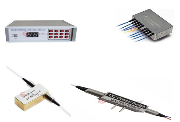
Optical switch is an optical device that enables signals to be selectively switched from one circuit to another in optical fibers or integrated optical circuits (IOCs). It is widely used in optical switching, configuration optical add/drop multiplexer(OADM), optical fiber ring protection and optical cross and connection system. It could be divided four types, opto-mechanical optical switch, MEMS optical switch, solid-state fiber optical switch and rackmount & benchtop optical switch. Optical switch is one of the main factors to affect the optical performance of the fiber network. It plays a very important role in the optical network.

optical switch types

Functionality of Optical Switch

The functionality of an optical switch can be described as an optical connection. A connection is the association between two ports on a switch and is indicated as a pair of port identifiers (i, j), where i and j are two ports among which the connection is established. An optical signal could be applied to one of the connected ports. However, the nature of the signal emerging at the other port depends on the optical switch. A connection can be in the on state or the off state. A connection is said to be in the on state if an optical signal applied to one port emerges at the other port with essentially zero loss in optical energy. A connection is said to be in the off state if essentially zero optical energy emerges at the other port.

Connections established in optical switches can be unidirectional or bidirectional. A unidirectional connection only allows optical signal transmission in one direction between the connected ports. A bidirectional connection allows optical signal transmission in both directions over the connection. Connections in passive and transparent optical switches are bidirectional. The same as, if a connection (i, j) is set up, optical transmission is possible from i to j and from j to i.

A passive optical switch does not have optical gain elements, but an active optical switch has optical gain elements. An all-optical switch is a transparent optical switch in which the actuating signal is also optical. Thus an optical signal is used to switch the path another optical signal takes through the optical switch.

Key Features of Optical Switch
  • Compact design
  • Short switching time
  • Low cross talk, Low Insertion Loss
  • Wide operating wavelength Range
  • Highly Stability & Reliability
  • Epoxy-free on optical path
  • Single mode or Multimode optional
Applications of Optical Switch
  • Wavelength selective switches
  • R&D in laboratory
  • Fiber sensor
  • Channel blocking
  • Optical channel monitoring in optical networks
  • Module and System Integration
  • Metropolitan Area Network
  • Network protection and restoration
  • Instrumentation, testing, and measurement

Optical switching technology is driven by the need to provide flexibility in optical network connectivity. With this article, we have learned the basic knowledge of optical switch and known that it is widely used in passive optical network.  In fact, there are more other passive optical components used in passive optical work, such as optical circulator, optical attenuator, and fiber collimator and so on. We will learn one by one in this blog. In addition, if you have any requirements of passive optical components, we welcome you to visit Fiberstore, as it  is a professional supplier in this field.

100 BASE-FX Mdeia Components

The 100BASE-FX fiber optic media system provides all of the advantages of a 10BASE-FL fiber optic link segment, while operating ten times faster. Distances of 2 km (6561.6 feet) over multimode fiber optic cables are possible when operating 100BASE-FX segments in full-duplex mode. Considerably longer distances are possible when using single mode fiber segments. This is why the 100BASE-FX media system is a popular choice for Ethernet backbone networks. The following set of media components are used to build a 100BASE-FX fiber optic segment:

● Fiber optic cable.
● Fiber optic connectors.

Fiber Optic Cable

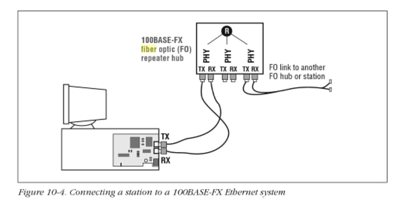
The 100BASE-FX specification requires two strands of multimode fiber optic (MMF) cable per link, one for transmit data, and one for receive data, with the signal crossover (TX or RX) performed in the link as shown in Figure 10-4. There are many kinks of fiber optic cables available, ranging from simple two-strand jumper cables with PVC plastic for the outer jacket material on up to large inter-building cables carrying many fibers in a bundle.

The typical fiber optic cable used for a 100BASE-FX fiber link segment consists of a graded-index MMF cable. These fibers optic cables have a 62.5 um fiber optic core and 125um outer cladding (62.5/125). The wavelength of light used on a 100BASE-TX fiber link segment is 1350 nanometers (nm). Signals sent at that wavelength over MMF fiber can provide segnment lengths of up to 2000 meters (6561 feet) when operating the link in full-duplex mode. More details on installing and using fiber optic cables and connectors can be found, Fiber optic cables and connectors.

Fiber Optic Connector

The medium-dependent interface (MDI) for a 100BASE-FX link may be one of three kinks of fiber optic connector. Of the three, the duplex SC connector shown in Figure 10-3 is the recommended alternative in the standard an is the one most widely used gy vendors. The SC connector is designed for ease of use; the connector is pushed into place and automatically snaps into the connector housing to complete the connection.
SC Connector

The ST connector may also be used. This is the same connector used for a 10BASE-FL link. It is a spring-loaded bayonet-type connector that has a key on an inner sleeve and an outer baynoet ring. To make a connection, you line up the key on the inner sleeve of the ST plug with a corresponding slot on the ST receptacle, then push the connector in and lock it in place by twisting the outer bayonet ring. According to the standard, the FFDI fiber optic media interface connector (MIC) may also be used on 100BASE-FX equipment: however, this optional connector has not been adopted by equipment vendors.

Connecting a Station to 100BASE-FX Ethernet

Figure 10-4 shows a computer equipped with a 100BASE-FX Ethernet adapter. In this example, the adapter card comes with an SC duplex connector, which makes a connection to the fiber cables that connect to the repeater hub. The repeater hub in the figure is shown with three pairs of 100BASE-FX SC connectors and built-in transceivers. A signal crossover is required to make a connection between the 100BASE-FX transceiver in the station, and the 100BASE-FX transceiver located in each repeater or switching hub port.

100BASE-FX

Fiberstore as the main professional fiber optic products manufacturer in china offer a various kinds of fiber cable connectors, FC Connectors, LC Connectors, SC Connectors, MPO Connectors and ST Connectors. You can buy fiber optic connection products on our store with your confidence. All of fiber optics supplies with high quality but low price.  Except fiber optic connector, we provide various types of fiber patch cords including single mode, multimode, multi core, and armored versions. You can aslo find fiber optic pigtails and other special patch cables here. For most of them, the SC, ST, FC, LC, MU, MTRJ, E2000, APC/UPC connectors are all available, even we supply MPO/MTP fiber cables.

Auxiliary Video Inputs Resolution and Refresh Rate

At the time of writing, the PC video input (VGA-DVI) and the document camera (DVI-HDMI) on the Cisco TelePresence codec operate at 1024×768 resolution with a refresh rate of 60Hz. The PC must be configured to output this resolution and refresh rate on its VGA output interface. Likewise, the document camera must be configured to output this resolution and refresh rate on its DVI output interface. The majority of PCs on the market at the time the product was designed use 1024×768 resolution and VGA interfaces, although an increasing number of models are beginning to support higher resolutions and are beginning to offer DVI and even HDMI interfaces instead of, or in addition to, VGA. Future versions of the Cisco TelePresence codec might support additional resolutions, refresh rates, and interface types for these connections.

VGA is an analog interface. DVI comes in three flavors: DVI-A that is analog, DVI-D that is digital, and DVI-I that can dynamically sense whether the connected device is using analog (DVI-A) or digital (DVI-D). It is worth mentioning that the first generation Cisco TelePresence codec offers a DVI-A connector for the PC connection. The other and of the cable that attaches to the PC is VGA. So the signal from the PC is a VGA analog to DVI-A analog connection. Now we will introduce you the VGA and DVI fiber video converter from our fiberstore.

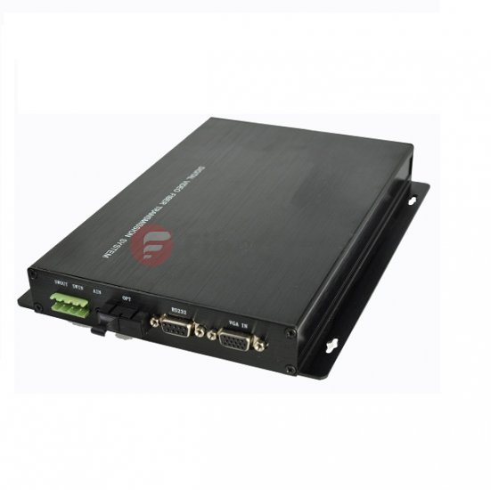
Fiberstore’s VGA Video Multiplexer,a flexible professional solution for long distance transmission of high resolution VGA or RGB Component Video signals through single fiber solutions, and single-mode or multi-mode fiber cables which allow for the transmission of accompanying stereo audio, RS232 data, Loopback output and support USB Keyboard/Mouse. applications include specialized Media Display, Security Systems, Universities, Industrial Monitoring, Airport / Airplane / Metro / Railway and large-scale conference sites including stadiums, where long distance transmission of computer video signals are necessary, fiber optic transmission ensures high quality signals with no interference.

VGA Video Converter

Fiberstore’s DVI Fiber Video Converter are the perfect choice for both large and small Pro AV installations. Featuring DVI video resolutions up to WUXGA 1920×1200 and HDTV video resolutions up to 1080p. Fiberstore’s DVI Fiber Optic Converter, a flexible professional solution for long distance transmission of high resolution video signals through single fiber solutions, and single-mode or multi-mode fiber cables which allow for the transmission of accompanying stereo audio, RS232 data, Loopback output and support USB Keyboard/Mouse. applications include specialized Media Display, Security Systems, Universities, Industrial Monitoring, Airport / Airplane / Metro / Railway and large-scale conference sites including stadiums, where long distance transmission of computer video signals are necessary, fiber optic transmission ensures high quality signals with no interference.

HDMI

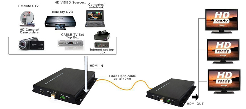
Fiberstore supply SDI Digital over fiber video converterr, 3G-SDI Digital over fiber video converter, HD-SDI over fiber video converter, and SDI-HDMI over fiber video converter. All of our optical/electric interfaces are in accordance with international standards, free of adjustment prior to mounting and applicable in various operating environments. Please feel free to contact us for all your Digital SDI&HDMI&VGI and other video conversion requirements.

What is the Meaning of 100G Channels Networks to Service Providers

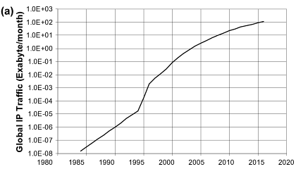
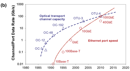
As the traffic demand continues growing, telecom network providers have planned introducing the newly developed coherent 100G transport software in their networks to satisfy the demand. History shows us that network service providers have made use of every stage of the new channel capacity available from equipment developers.
Fiberstore

Fiberstore

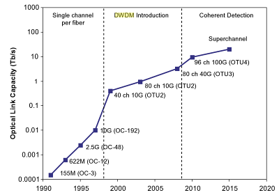
The figure below shows the timeline for increases in fiber link capacity operating provider’s networks. In early 1990s, a capacity of a few hundred Mbps per link and just on channel per strand of fiber inside a transport network was typical. As email was a new communication tool in the centre 1990s, the fiber capacity gradually increased to a couple Gbps, and this growth continued to deal with the demand that individuals needed to start accessing the web. Into the later 1990s, fiber capacity grew even larger with the deployment of 10 Gbps channels and WDM techniques to multiplex and amplify a small number of wavelengths (4-8) on a single fiber pair. In early 2000s, Internet usage became commonplace but networking kept pace using the introduction of DWDM techniques that could support 40, 80, or maybe more wavelengths allowing fiber capacities to be near Tbps. For MUX/DeMUX solutions with different DWDM wavelengths, please visit Fiberstore. This extensive fiber capacity increase helped the transport network support continually increasing user demands. In the late 2000s, the introduction of 40G channels gave the capability of the networks another boost. By 2010, video sharing on the web by applications such as YouTube along with other video when needed (VoD) services started to stress existing network capacity. The development of the fiber capacity to approximately 10 Tbps per fiber. This will address near term capacity requirements, but moving forward, cloud computing along with other bandwidth hungry applications will continue to consume network resources, and new optical techniques to increase channel capacity and optical link capacity is going to be introduced progressively.
Fiberstore

The coherent 100G PM-QPSK system selected by the industry is able to run at the same channel spacing (50 GHz) like a 10G commercial system does in existing networks, and so the 100G system can offer enough capacity for network service providers to support customer demands in the near term without a network overbuild. Using the new 100G system, service providers expect the cost per bit declines in the same rate as or perhaps a faster pace than the decline rate of serves prices service providers can charge their clients, so that providers are able to remain competitive.

Before telecom service providers introduce commercial coherent 100G software in their networks, normally a series of technology trials must be conducted in their existing networks to determine the performance of the new technology. The primary purpose of the technology trials would be to guarantee the 100G channel behaves well in existing fiber network infrastructures. Fiber routes within the field may have high transmission attenuation, high PMD values, multiple connections and splicing points, various fiber types, etc. While most lab experiments are conducted with fiber loop configurations, a linear configuration in field trials is much more preferred to mimic optical links in tangible networks. Field trials give network providers proper expectation for that performance of the systems, which will be installed in networks. Issues present in these trials may also be sent back somewhere developers for further product improvement. In a single field trial a 112 Gbps coherent channel transmitted over 1730 km deployed DWDM link in a service provider’s network, while using DWDM Multiplexer. A carrier suppressed RZ and differential PM-QPSK modulation format was utilized for the channel in the trial. The trial results show that the coherent 100G channel has the capacity to serve long term routes. The plug and play performance of the equipment and robustness to chromatic dispersion and PMD impairments was demonstrated in the trial. Co-propagating the 100G channel with adjacent 10 Gbps signals without touching the fiber infrastructure proved one viable migration road to next generation networks. It’s a requirement for service providers to maintain the networks scalable and cost-effective while increasing channel capacity and fiber ability to have next-gen multi-terabit networks.

In another field trial a real-time, single carrier, coherent 100G PM-QPSK upgrade of the existing 10G/40G terrestrial system was demonstrated inside a service provider’s network. The field experiment shows the performance of the 100G channel sufficient for error-free operation after FEC over installed 900 km and 1800 km fiber links. The experiment proves that flexible and seamless 100 Gps channel upgrades to existing 10G and 40G DWDM systems are possible and practical.

Yet another coherent 100G channel field trial was performed on dispersion shifted fiber (DSF) links. The trial involved eighty 127 Gbps channels propagating on a deployed fiber link. L-band specturn was used to avoid zero dispersion reason for specturn, differnet from using C-band for SMF or NZDSF for additional common cases. The 100G channels, with 50 GHz channel spacing, traveled over 458 km DSF successfully with L-band EDFA only. Sufficient Q-margins remained as left for the 80 channels following the 458 km transmission. This field trial demonstrated that a 10 Tbps calss capacity DWDM product is feasible underneath the condition of small local dispersion by deploying coherent detection and high overhead (20%) coding gain FEC. This trial represented the highest fiber capacity in the field at the time the trial was conducted.

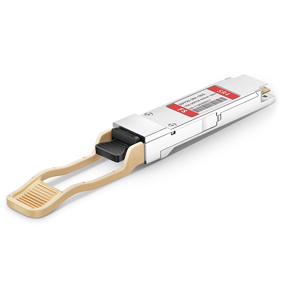
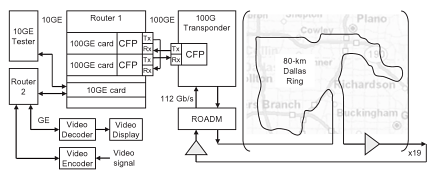
The reason for introducing 100G channels into transport networks is to carry large IP data traffic across IP networks, therefore, an “end-to-end” transport trial, i.e. an entire data transport trial from data equipment to data equipment, using a coherent 100G channel transmission over a long distance, is particularly meaningful to service providers. One such field trial, which involved a worldwide network company, a data equipment developer, a transport equipment developer, and a client interface developer, continues to be reported. In this trial a 112 Gbps single carrier real-time coherent PM-QPSK channel from a transponder carried native IP packet traffic over 1520 km field deployed fiber, with 100GbE router cards and 100G CFP interfaces. This trial shows the feasibility of interoperability between multi-suppliers’ equipment for 100G transport. This field trial, which fully emulated an operating near-term deployment scenario, confirmed that all key components required for deployment of 100GbE technology are maturing at the time the trial was conducted (early 2010).
Fiberstore

The detailed configuration of the trial is shown in the figure. A 10GbE test set generates 10GbE traffic for Router 1 and also the test set can be used for analyzing packet throughput too. Another router (Router 2) is used to accept a GbE signal containing a video signal using a video encoder and to send the recording signal to some video display via a video decoder following the signal transverses the trial path. Router 2 connects to Router 1 with another 10GbE link, containing the video traffic. Router 1 routes both 10GbE data streams to one of the 100GbE cards and routes back the 10GbE data streams form the other 100GbE card towards the corresponding 10GbE ports. The 100G CFP interfaces are used to connect 100GbE cards and the 100G transponder. The transmitter port of the CFP in the first 100GbE card is connected to the receiver port of the CFP in the transponder and also the receiver port of the second 100GbE card is linked to yhe transmitter port from the CFP in the transponder. The receiver port from the CFP in the first 100GbE card and also the transmitter port of the CFP in the second 100GbE card are of a fiber jumper (fiber patch cable) to shut the loop. The CFP transponder sends the 112 Gbps signal towards the fiber route-equipped having a long haul DWDM system. Both directions of the inline amplifiers have been used for the trial to save on equipment needed.

With these successful 100G system field trials, telecom network providers and other network operators have been convinced that the only optical carrier PM-QPSK with coherent detections is easily the most promising 100G channel solutions, at least for the time being. Now commercial 100G systems are for sale to the customers of the equipment developers and the customers are likely to enjoy the ten times fiber capacity begin their networks.
 

Synchronous Optical Networking Introduction

Synchronous Optical Networking is usually called SONET for short. The SONET standards were coded in the mid-1980s to consider benefit of low-cost fiber optic transmission. It defines a hierarchy of data rates, formats for framing and multiplexing the payload data, as well as optical signal specifications (wavelength and dispersion), allowing multi-vendor interoperability.

SONET may also be referred to as “T-1 on steroids”. Can you explain that? As you may know, the digital hierarchy (DS-0, DS-1, DS-2, DS-3 and much more) was created to provide cost-effective multiplexed transport for voice and data traffic from one location inside a network to a separate.

SONET and SDH (Synchronous Digital Hierarchy) are two equivalent multiplexing protocols for transferring multiple digital bit streams using lasers or LEDs (light-emitting diodes) over the same optical fiber. They were made to replace PDH (Plesiochronous Digital Hierarchy) system to get rid of the synchronization issues that PDH Multiplexer had. SONET is synchronous, which means that each connection achieves a continuing bit rate and delay. For example, SDH or SONET might be utilized to allow several Internet Service Providers to talk about exactly the same optical fiber, without being affected by each others traffic load, and without having to be able to temporarily borrow released capacity from one another. SONET and SDH are considered to become physical layer protocols since they offer permanent connections and do not involve packet mode communication. Only certain integer multiples of 64kbits/s are possible bit rates.

SONET is really TDM(time division multiplexing) based and this causes it to be readily supported fixed-rate services such as telephony. Its synchronous nature is designed to accept traffic at fixed multiples of the basic rate (64kbit/s), without requiring variable stuff bits or complex rate adaptation.

The SONET data transmission format is based on a 125us frame composed of 810 octets, of which 36 are overhead and 774 are payload data. The fundamental SONET signal, whose electrical and optical versions are referred to as STS-1 and OC-1, respectively, is thus a 51.84Mb/s data streams that readily accommodate TDM channels in multiples of 8 kb/s.

It is important in fiber optic network that SONET can be used to encapsulate PDH and other earlier digital transmission standards. It is also used directly to support either an ATM (Asynchronous Transfer Mode) or packet over SONET/SDH (POS) networking. So SONET/SDH is actually a generic all-purpose transport container for moving both voice and knowledge traffic. They in themselves aren’t communications protocols.

SONET brings by using it a subset of benefits that make it differentiate themselves from competitive technologies. These include mid-span meet, improved operations, administration, maintenance, and provisioning (OAM&P), support for multipoint circuit configurations, non-intrusive facility monitoring, and the capability to deploy a variety of new releases.

Improved OAM&P is among the greatest contributions that SONET brings to the networking field. Element and network monitoring, management, and maintenance has always been something of the catch-as-catch-can effort due to the complexity and diversity of elements inside a typical service provider’s network. SONET overhead includes error-checking ability, bytes for network survivability, and a diverse set of clearly defined management messages.

Related Article: How Much Do You Know About SONET/SDH SFP Module?