NAT: Why Do We Need It?

NAT, which is critical to the IPv4 networks we still use today, has been hotly debated as the IPv6 grows with more addresses. However, since the IPv6 is not full-fledged, the existence of NAT still makes sense. Here I will introduce NAT definition and figure how NAT works and why we need it.

What Is NAT?

NAT, known as network address translation, is the method adopted by a firewall or router to assign the public addresses to the devices work in the a private network.

It translates the private IPv4 addresses we use in our internal networks into public IPv4 addresses that can be routed over the internet. As we all know, the private addresses may be occupied by connected local service—computers, game consoles, phones, fiber switches etc. to communicate with the modem/router and other devices on the same network. However, the home network connection uses a single public IP address to access the internet. Given this, NAT is responsible for translating the IP address of every device connected to a router into a public IP address at the gateway. Then those devices can connect to the internet.

NAT(network address translation)

NAT: Why We Need?

Assume that you have 3 PCs, a gigabit Ethernet switch which connects 6 PCs, a 10 gigabit switch connecting 6PCs and one smart phone, two ipads and all of them need to work at the same time, then you need to get each of them an IP address accessible to the Internet. But due to a lack of IPv4 IP address space, it is hard to handle the massive number of devices we use every day. Well, the network address translation, proposed in 1994, has become a popular and necessary tool in the face of IPv4 address exhaustion by representing all internal devices as a whole with a same public address available. Together with its extension named port address translation, the network address translation can conserve IP addresses.

Safety, another issue we may concern when accessing the external internet, can partly be addressed by network address translation which servers as a strict controller of accessing to resources on both sides on the firewall. The hackers from outside cannot directly attack the internal network while the internal information cannot access the outside world casually.

How Does NAT Work

A router carrying NAT consists of pairs of local IP addresses and globally unique addresses, by translating the local IP addresses to global address for outgoing traffic and vice versa for incoming traffic. All these are done by rewriting the headers of data packets so that they have the correct IP address to reach the proper destination.

There are generally two types of NAT: dynamic and static.

In dynamic NAT, we map inside local addresses in internal network to global addresses so that they can access resources on the internet. The router responds to the hosts who want to access the internet with an available public IPv4 address so that they can access the internet.

In static NAT, we usually map an internal local address to a global address so that hosts on public networks can access a device in the internal network.

Conclusion

In a word, before the full transition of IPv6, NAT can guarantee the smooth internet surfing no matter how many devices you’ve got. Knowing what it is and how it works with network address will help you establish a clear understanding of it so that you can make good use if it.

24-Port Switch Selection: Which Is the Suitable Choice?

An Ethernet switch acts as a bridge to connect different parts of a network together. Although many routers also possess the network switching capabilities and multiple Ethernet ports, the Ethernet switch is not the replacement for routers. It is worth emphasizing that Ethernet switches are smarter than routers in that they operate at the data link layer (Layer 2) and the network layer (Layer 3) of the OSI Reference Model and therefore support any packet protocol. Ideally, switches will make better use of bandwidth if you prefer wired to wireless connections but have more devices than available Ethernet ports. On the other hand, an Ethernet switch is a costly way to expend the network in home or small business. So it is very important to invest an Ethernet switch with the appropriate number of ports to fit your needs. In the midst of various Gigabit Ethernet switches, a 24 port switch is considered as the most common Gigabit switch that connect devices in a local area network. Then this article will explore how to select a suitable 24-port switch.

Popular 24 Port Switch in the Market

FS S3900-24F4S 24-Port Switch

FS S3900-24F4S 24-port switch comes with 20x 100/1000BASE SFP, 4x 1GE combo and 4x 10GE SFP+ slots. The flexible port combination form provide a high bandwidth aggregation connectivity for multiple switch in network to enhance network capacity. Moreover, it is a stackable SFP managed switch, which can provide true stacking of up to 6 switches in a stack acting as a single unit with totally 168 ports (144x 1G Ports and 24x 10G ports). The switching capacity is 128Gbps. This 24-port Gigabit managed switch fits for enterprise network operators who need high performance and low power processor to provide full speed forwarding and line-dormant capacity.

S3900-24F4S Stackable Switch

Figure 1: FS S3900-24F4S 24-Port Gigabit Switch

Cisco SGE2000 24-Port Switch

Cisco SGE2000P comes with 24 10/100/1000BASE-T RJ45 ports and 4 shared Gigabit SFP slots. This 24 port switch can provide ACL (access control lists), DoS (denial-of-service), VLAN and IEEE 802.1X port authentication. And the enhanced quality of service (QoS) and traffic-management features help ensure clear and reliable voice and video communications. This Gigabit network switch enable you to take advantage of the comprehensive feature set for a better-optimized, more secure network.

Cisco SGE2000 24-Port Gigabit Switch

Figure 2: Cisco SGE2000 24-Port Gigabit Switch (Source: Cisco)

NETGEAR ProSAFE GS724T 24-Port Gigabit Switch

The Netgear ProSafe GS724T is armed with 24 copper 10/100/1000 ports and 2 SFP 100/1000 ports. Each port can transfer data at maximum throughput for a total maximum switching speed of up to 48 Gbps. This 24-port switch is intended for SMB organizations using the switch for applications like VoIP, video conferencing, and system security, etc. And it features a fanless system, allowing the switch to work silently without overheating. This is great for use on homelab, as its quiet operation won’t cause a distraction.

NETGEAR ProSAFE GS724T 24-Port Gigabit Switch

Figure 3: NETGEAR ProSAFE GS724T 24-Port Gigabit Switch (Source: NETGEAR)

TP-Link TL-SG1024 24-Port Switch

The TP-Link TL-SG1024 features 24 Gigabit Ethernet ports and non-blocking switching, which can provide large file transferring and also be compatible with 10Mbps and 100Mbps Ethernet devices. Moreover, this network switch has 48Gbps switching capacity with 8K MAC address table, 10KB Jumbo Frame and 4MB buffer memory. This TP-Link switch is a fanless rack mount design with LED diagnostic lights, so you can easily tell which ports are in use. It can automatically adjust power consumption according to the link status to limit the carbon footprint of your network. The price is $69.99 on Amazon. So this fanless Ethernet switch is good for your wallet both because it is inexpensive to buy and because of its energy-saving technology.

TP-Link TL-SG1024 24-Port Gigabit Switch

Figure 4: TP-Link TL-SG1024 24-Port Gigabit Switch(Source: TP-Link)

Comparison of 24-Port Switch

Gigabit Switch Mode Ethernet ports Gigabit SFP SFP+ Uplink ports Switching Capacity Forwarding Rate Power Consumption Price
FS S3900-24F4S 24 4 combo 4 128Gbps 95Mpps 43W $400
Cisco SGE2000 24 4 / 48Gbps 35.7Mpps 90W $390
NETGEAR ProSAFE GS724T 24 2 / 48Gbps No Information 29W $219.99
TP-Link TL-SG1024 24 / / 48Gbps 35.7Mpps 13.1W $69.99

From the chart we can see, all the Gigabit switches listed above provide 24 port Ethernet RJ45 ports, only FS S3900-24F4S 24 port switch has 4 SFP+ uplink ports. They have some characteristics in common that make them suitable for being used in places like home or small business office. In terms of the power consumption, TP-Link TL-SG1024 and NETGEAR ProSafe GS724T are lower than others, but the huge price spread exists between these two switches because NETGEAR ProSafe GS724T has another two SFP ports for more flexible application. Among these four switches, if you have no limited cost budget, FS S3900-24F4S is a good choice. It has a more flexible port combination and higher switching capacity, that is why it may cost a little more than the other three switches. If you need stronger data transferring capability, FS S3900-24F4S is a better choice considering its forwarding rate. On the contrary, TP-Link TL-SG1024 is the best budget choice. If you want a fanless switch, NETGEAR ProSafe GS724T is an inexpensive and reliable choice, but the install program only works on Windows and the secure management is very difficult to be enabled.

Conclusion

When choosing a Gigabit Ethernet switch, the first factor to consider is how many devices need to be networked together. Purchasing a network switch with too few ports and not enough capacity will prove ineffective, and one that is too large can be a waste of money. Generally, small offices with a few employees should start with a 16-port switch, but a business that is looking to expand its operations soon needs a 24-port switch. So 24-port switch is the most future-proofing and cost-effective choice in small business network. Except for the above mentioned S3900-24F4S, FS.COM also provides other cost-effective 24 port switches for different demands. For instance, S3900-24T4S is a Gigabit stackable managed switch with 24 10/100/1000BASE-T ports and 4 10GE SFP+ uplinks ports.

Related Article: 48-Port 10GE Switch Selection: What Is the Right Choice?

FS 24-Port PoE Switch for High-density PoE Installations

Due to the increased requirements for IP surveillance networks, the appearance of PoE switches gives you an easy way to add PoE devices to the network. They are ideal for small business networks that need to inexpensively use PoE to deploy wireless access points, IP phones and IP cameras. The PoE switch models are available with 4, 8, 16, 24 or 48 ports, although other variants are also available. 24 port PoE switch is the most prevalent variant on the market. So why does your network need a 24-port PoE switch and how can the network benefit from deploying it? This article explains it in detail.

Why Your Network Needs A 24-Port PoE Switch?

When choosing an Ethernet switch, the most important is to check whether the number of ports on the switch is enough to connect all your devices. The same is true when choosing PoE as a switch. PoE ports are flexible to connect with Cat5e cable without additional settings. Generally, the PoE switch has uplink ports, which allow long-distance data transmission between switches. Switches without uplink ports can still be linked together but you may experience bandwidth issues with switch-to-switch data flow. A 24-port PoE switch fully complies with the IEEE 802.3af standard for PoE up to 15.4W per port and the latest IEEE 802.3at standard for PoE+ up to 30W per port.

On the whole, the 24-port PoE switch can greatly reduce the associated cost with smaller PoE installations in a home or small business environment. At the same time, it will allow you to expand your network to areas with no power lines. Essentially, the plug-and-play PoE switch will automatically detect whether connected devices are PoE and send power accordingly. For a 24-port PoE-managed switch with a power budget of 370W, you need a total power per port of 30W to power an IP camera network. And you can continue to add IP cameras until you reach your budget. If you have 2 SFP ports, you can also connect to multiple switches. Keep in mind, that if you exceed the power threshold and the devices aren’t getting sufficient power, they may not boot up properly. Finally, please ensure you cheque the power requirement for your PoE-enabled device, the standard it complies with and the overall PoE budget of your installation before purchasing a 24-Port PoE switch.

FS S3400-24T4FP 24-Port PoE Managed Switch – 4 x 1Gb Combo Uplinks, 370W

FS S3400-24T4FP managed PoE switch comes with 24 10/100/1000Base-T RJ45 Ethernet ports, 1 console port, and 4 combo ports for fibre uplinks. It offers network managers the advantage of connecting up to 24 power-hungry wireless access points, IP security cameras, LED lighting or VoIP endpoints to the network with a single wire for power and connectivity. With its robust PoE power budget of 370W, the S3400-24T4FP switch supports denser deployment of PoE devices. This switch has a 56Gbps switching capacity with an 8K MAC address table. The power supply is supportive as well, which is about 100-240V. This is a solidly built excellent switch from the firm with a data transfer rate of 1,000 Mb/s. It represents an ideal switching solution for even advanced SMBs or entry-level enterprises which demand industrial, surveillance, IP Phone, IP Camera or Wireless APs. All in all, the PoE switch provides security, performance, quality of services, central management and other network control capabilities.

Key Features:
  • Up to 24 PoE+ Ports, Total Budget 370W
  • 3 Built-in Fans and Single Power Supply
  • Support ERPS, QoS, OSPF, L2 Multicast Functions, RIP
  • Support SSH, ACL, AAA, 802.1X, RADIUS, TACACS+, etc. for Security
  • Advanced Network Monitoring Using SFlow
  • Support WEB/CLI/SNMP/SSH for Flexible Operation

Conclusion

PoE switch is a cost-effective solution to increase the reliability and security of networks by providing centralized backup power to all connected IP surveillance devices. Before purchasing PoE switches, try to know as many details about the switch specifications as possible and also your own needs. FS S3400-24T4FP managed PoE switch is an affordable switch to support SMB switching needs for wireless converged networks and IP surveillance. If you prepare for growth and buy infrastructure for the long term, you will find this 370W PoE power budget provides headroom for future expansion.

Related Article: Deploying 48-Port Gigabit PoE Managed Switch in Different Networks

Layer 3 Switch VS. Router

In the OSI model, we know that traditional network switch operates at Layer 2 while network routers operate at Layer 3. Besides, switches are understood to be forward traffic based on MAC address, while routers perform the forwarding based on IP address. Layer 3 switches have a lot in common with traditional routers: they can also support the same routing protocols, inspect incoming packets and make dynamic routing decisions based on the source and destination addresses inside. For this reason, many networking beginners are puzzled over the definition and purpose of a Layer 3 switch. So what is on earth Layer 3 switch and what is the difference between Layer 3 switch vs. router?

Layer 3 Switch

Layer 3 switch is also called multilayer switch. It is a specialized hardware device used in network routing, which is conceived as a technology to improve network routing performance on large local area networks (LANs) like corporate intranets. A Layer 3 switch is both a switch and a router. So Layer 3 switch is a switch that can route traffic, and a router with multiple Ethernet ports has a switching functionality. It can switch packets by checking both IP addresses and MAC addresses. On this account, Layer 3 switches separates ports into VLANs and perform the routing between them, in addition to supporting routing protocols such as RIP, OSPF and EIGRP.

Layer 3 switch

Layer 3 Switch VS. Router

From the basics of Layer 3 switch, it may seem to perform the same functionality with the router. In fact, they have some key distinction facts. The key differences between Layer 3 switches and routers lay in the hardware technology used to build the unit. The hardware inside a Layer 3 switch merges that of traditional switches and routers, replacing some of a router’s software logic with hardware to offer better performance in some situations. The table below illustrates the differences between Layer 3 switch and router.

Layer 3 Switch VS. Router

Layer 3 Switch vs. Router: Main Differences:
  • Cost – Layer 3 switch is much more cost effective than router for delivering high-speed inter-VLAN routing. High performance router is typically much more expensive than Layer 3 switch.
  • Port density – Layer 3 switch has much higher port count while router has a lower port density than Layer 3 switch.
  • Flexibility – Layer 3 switch allows you to mix and match Layer 2 and Layer 3 switching. It means that you can configure a Layer 3 switch to operate as a normal Layer 2 switch.
  • WAN technologies support – Layer 3 switch is limited to usage over LAN environment where Inter VLAN routing can be performed. However, when it comes to working on WAN and edge technologies, Layer 3 switch lags behind. Router is the front runner in such scenario where WAN technologies such as Frame Relay or ATM need to be fostered.
  • Hardware/Software decision making – The key difference between Layer 3 switch and router lies in the hardware technology used to making forwarding decision. Layer 3 switch uses ASICs for forwarding decisions. Conversely, the router makes forwarding decisions based on hierarchical Layer-3 addresses.
Layer 3 Switch with VLANs

As here is mentioned the VLAN, so let’s talk about it firstly. A VLAN (virtual LAN) is a logical subnetwork that can group together a collection of devices from different physical LANs. VLANs can improve the overall performance of busy networks. So they are often set up for improved traffic management by larger business computer networks. With a VLAN, traffic can be handled more efficiently by network switches.

Each virtual LAN must be entered and port-mapped on the switch. Routing parameters for each VLAN interface must also be specified. Some Layer 3 switches implement DHCP support that can be used to automatically assign IP addresses to devices within a VLAN. Alternatively, an outside DHCP server can be used, or static IP addresses configured separately. The diagram below shows an example of a layer 3 switching routing between VLANs through its two VLAN interfaces.

Layer 3 Switch with VLAN

These switches are most commonly used to support routing between virtual LANs (VLANs). Benefits of Layer 3 switches for VLANs include:

  • Reduction in the amount of broadcast traffic
  • Simplified security management
  • Improved fault isolation
Conclusion

From what we have discussed about Layer 3 switch vs. router, Layer 3 switch may be more preferable in result of its capability of routing and switching. Besides, it can perform as a top of rack device and a distributed core switching layer at the same time. This reduces the L2 complexity of the client access layer, which makes the network more reliable and easier to manage. FS.COM can provide a comprehensive, scalable and secure portfolio of switches for enterprise and service provider networks. There are also a huge stock of compatible fiber optic transceivers and cables. For more details, please visit www.fs.com.

Ethernet Switch: How Much Do You Know It?

Today, all plants are virtually networked via Ethernet. High requirements are placed on the network infrastructure and network components. Ethernet switch is the integral piece of IT infrastructure, capable of receiving, processing and transmitting data between two devices connected by a physical layer. Due to the increasing application of big data analytics and cloud-based services in various end-user segments, data centers are envisaged to fuel the adoption of Ethernet switch. The augmented global demand for data centers is the key driver for the growth of Ethernet switch market. To satisfy the large and ever-increasing market for Ethernet switch, there are many varieties of switches offered different purposes. This article will help you get a deep understanding of the different types of Ethernet switch.

What is an Ethernet Switch?

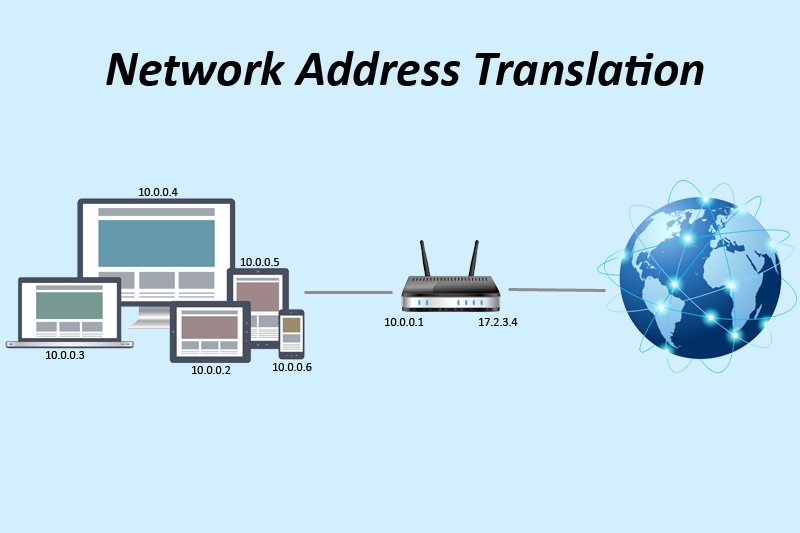
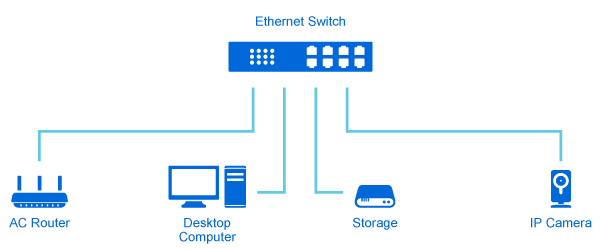
A Ethernet switch is a tool for connections between the systems and equipment to forward data selectively to one or more connected devices on the same network. These connections are generally created through the use of structured cabling that links both the station side and the device that you are trying to share data with, such as a server or another computer. In this way, Ethernet switch can control the flow of traffic passing through a network, maximizing the network’s efficiency and security. More advanced Ethernet switch, called managed switch, are also capable of providing additional functions, such as network load balancing, address translation or data encryption and decryption.

FS Ethernet switch

How Dose an Ethernet Switch Work?

Ethernet switch links Ethernet devices together by relaying Ethernet frames between the devices connected to the switches. By moving Ethernet frames between the switch ports, a switch links the traffic carried by the individual network connections into a larger Ethernet network. Ethernet switches perform their linking function by bridging Ethernet frames between Ethernet segments. To do this, they copy Ethernet frames from one switch port to another, based on the Media Access Control (MAC) addresses in the Ethernet frames. Ethernet bridging was initially defined in the 802.1D IEEE Standard for Local and Metropolitan Area Networks: Media Access Control (MAC) Bridges. The standardization of bridging operations in switches makes it possible to buy switches from different vendors that will work together when combined in a network design. That’s the result of lots of hard work on the part of the standards engineers to define a set of standards that vendors could agree upon and implement in their switch designs.

diagram of Ethernet switches connections

Different Types of Ethernet Switch

Ethernet switch are broadly categorized into two main categories – modular switches and fixed switches. Modular switches allow you to add expansion modules into the switches as needed, thereby delivering the best flexibility to address changing networks. Fixed switches are switches with a fixed number of ports and are typically not expandable. This category can be broken down even further into unmanaged, lightly managed, and fully managed.

Unmanaged Switch

An unmanaged switch is mostly used in home networks and small companies or businesses, as it is the most cost effective for deployment scenarios that require only basic layer 2 switching and connectivity. The unmanaged switch is not configurable and have all of their programming built in. It is ready to work straight out of the box. And it is the easiest and simplest installation, because of its small cable connections. An unmanaged switch is perfect in this situation since it requires the least amount of investment with regards to both expense and time.

Smart Switch / Lightly Managed Switch

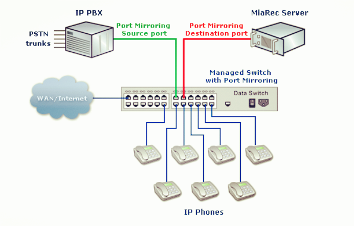
A smart switch is the middle ground between the unmanaged and fully managed switches. These smart switches offer limited customization, but do possess the granular control abilities that a fully managed switch has. In addition, smart switches offer certain levels of management, quality-of-service (QoS), security, but they are lighter in capabilities and less scalable than the managed switches. Smart switches tend to have a management interface that is more simplified than what managed switches offer. They also offer the capability to set up options like Quality of Service (QoS) and VLANs, which can be helpful if your organization has VoIP phones, or if you want to segment your network into work groups. Therefore, smart switches are the cost-effective alternative to managed switches. They are still valid choices for the regular consumer, as they are generally easy to use and you can glean a bit more information off of them on how your network is configured compared to unmanaged switches.

Fully Managed Switch / Enterprise Managed Switch

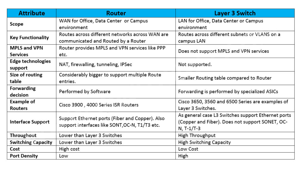
Managed Layer 2 Switch: A modern managed switch provides all the functionality of an unmanaged switch. In addition, it can control and configure the behavior of the device. This typically introduces the ability to support virtual LANs (VLANs), which is why almost all organizations deploy managed switches versus their cheaper alternatives.

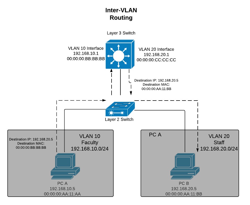
Managed Layer 3 Switch (Multilayer Switch): This type of switch provides a mix of functionality between that of a managed Layer 2 switch and a router. The amount of router function overlap is highly dependent on the switch model. At the highest level, a multilayer switch provides better performance for LAN routing than almost any standard router on the market, because these switches are designed to offload a lot of this functionality to hardware.

data-center-network-architecture

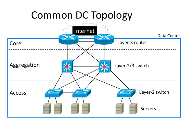
Managed switches are designed to deliver the most comprehensive set of features to provide the best application experience, the highest levels of security, the most precise control and management of the network, and offer the greatest scalability in the fixed configuration category of switches. As a result, they are usually deployed as aggregation/access switches in very large networks or as core switches in relatively smaller networks. Managed switches should support both L2 switching and L3 IP routing, though you’ll find some with only L2 switching support.

Conclusion

The Ethernet switch plays an integral role in most modern Ethernet local area networks (LANs). Mid-to-large sized LANs contain a number of linked managed switches. Small office/home office (SOHO) applications typically use a single unmanaged switch. This article has introduced different types of switches. Depending on the number of devices you have and the number of people using the network, you have to choose the right kind of switch that fits your space. FS.COM has provided a comprehensive set of Ethernet switches. If you have any requirements, welcome to visit our website for more detailed information.

How to Choose a Suitable Wireless Access Point for Business?

Wi-Fi technology has improved greatly in recent years. It has great impact on our life style and work habits. As an important component in this technology, wireless access points (APs) has become more prevalent than before, for they can provide a convenient way to wired networks. But it’s not one-size-fits-all, especially when it comes to businesses. They may suits large office spaces with heavy traffic, but not small offices with limited users. Of course, all situations cannot be treated as the same. Let’s take a look at how to choose a suitable wireless access point for your business.

What Can a Wireless Access Point Do for Your Business?

A wireless access point is a hardware device or configured node in a local area network (LAN) that connects to a wired router, switch, or hub via an Ethernet cable, and projects a Wi-Fi signal to a designated area. It can be used both in an office or a large building.

wireless asscess points applications

As we all know, business network is not like a home Wi-Fi network. The latter one only has a limited number of devices at one time, but the former need to handle numbers of connections simultaneously. Generally, wireless access points can handle over sixty connections each at the same time. When employees or guests connecting with desktops, laptops, tablets or mobile phones, they can get access to your wired network easily and quickly.

In a word, here are what the wireless access points can bring for your business:

  • Improve productivity by allowing employees to access company resources from anywhere in the workspace
  • Wireless access points compatible with PoE eliminate the need to run separate power line or install an outlet near the access point, which saves cost and installs time
  • Wireless access points supporting Captive Portal and Access Control List (ACL) give you more convenience to manage your Wi-Fi networks
Tips on Choosing Suitable Wireless Access Points

It’s not easy to select a suitable wireless access point for business networks if considering several factors. Well, it’s no doubt that the standards should be put in the first place. Therefore, I’ll talk more about other practical factors that may be ignored.

wifi access points

Upgradeability

As technologies are evolving so fast, it’s important to choose wireless access points that firmware upgrades. It is also beneficial if the upgrades can be done from a central access point, which automatically allocates the upgrade to other access points on the network.

Coverage Options

A wide range of wireless access points available for your business to choose from in the market. Depending on the area you’ll need to cover will be a main determining factor here. Will they be for indoor or outdoor use? Is there a need for considerable shielding for outdoor use? Before you adding the APs in your cart, these questions need to be answered at first.

Working Temperature

Wireless access points have a good working performance in a normal environment like office or mall. But we cannot exclude some extreme temperatures occur, especially in outdoor use. So have a clear view of the working temperatures with wireless access points is the key to determine how long your APs can work for you.

Price

Once you have known clearly which kind of wireless access points is suitable for your business networks, it’s time to compare the price. It’s obvious that price plays a vital role in the selection of wireless access points. According to your actual conditions to choose a suitable wireless access point. Be aware of the features that can simplify the process of installation.

Except for the considerations above, other factors such as speed and mounting style also need to be taken into account.

Summary

By installing access points through the workplaces, employees can roam freely from room to room without experiencing network interruptions. Their devices shift seamlessly from one access point to the next without dropping the connection through the workplaces, improving work efficiency greatly. Therefore, choosing the best wireless access points is important.

Why Is Managed Switch Good for Business Networks?

A network is a foundation to connect storage, servers, printers, PCs, and wireless clients with business-critical applications to enhance productivity and customer satisfaction. And network switches are like the tyres of a car. Without them, the “car” cannot work normally. No matter the large enterprises, or small and midsize businesses, their systems and applications are interconnected and rely on the network. Today’s post is to introduce the managed switch and why it is important for business networks.

Managed Switches Basics

A managed switch is a type of Ethernet switch that has a fixed number of ports. It is designed to deliver the most precise control and management of networks. They are usually deployed in large networks or as core switches in relatively smaller networks. To introduce the basics of a managed switch in detail, here take the 24 port PoE switch as an example (as shown in the below picture).

As shown in the picture, there are three types of ports on this switch: PoE port, SFP port and console port. The number of PoE ports is 24, and they can provide both power and data transmission. There are four SFP ports which include two Gigabit combo ports. These ports can connect with SFP fibre transceivers to uplink to the backbone switch at a long-distance location. The last kind of port is the console port which is for effective management. With a total power budget of up to 220 watts, this managed business Gigabit PoE switch provides a quick, safe and cost-effective Power over Ethernet network solution for small businesses and enterprises.

Benefits of Managed Switches

People who have work experience with switches know that unmanaged switches and managed switches are two common Ethernet switches in networking. And unmanaged switches seem to be a better choice in terms of cost. Therefore, maybe many business owners would ask, compared with managed switches, unmanaged switches are more cost-effective. Why do I need to choose a more expensive switch? Well, managed switches have other features which are more beneficial for your networks.

managed switch in network

Using SNMP (Simple Network Management Protocol) for Better Network Monitor

SNMP is a protocol that facilitates the exchange of management information between network devices. SNMP queries also can help cheque the health and status of devices in a network. Data displayed in an easily understood format is good for IT managers to monitor the performance of the network from a remote location. And it also helps to repair the problems without inspecting the switches or devices personally.

Port Monitoring for Troubleshooting

The function of the port monitoring feature of managed switches is to diagnose problems effectively. It copies the switch network traffic and forwards it to a single port on the same switch for analysis by a network analyser. Problems can be found by using the analyser on the monitor port without switching off the network.

Quality of Service (QoS) to Prioritise Your Network Traffic

This feature of managed switches allows you to prioritize your network traffic by assigning a higher priority to the critical traffic, which is beneficial to improve network performance and transmit delay-sensitive data such as real-time voice.

Apart from the features mentioned above, managed switches also have two features that cannot be ignored. One is that switches can be used in VLAN (Virtual Local Area Network) configuration to logically group devices as per the working departments, and managed switches can be used to isolate traffic between these groups, which allows better network performance and an additional level of security. Another one is redundancy which can protect the network when connection failures occur.

Conclusion

Managed switches, especially managed PoE switches, offer great expandability for growing business networks. With business network growth on the horizon, having a clear evaluation of the network requirements is important. If you want to have some input and control over the behaviour of traffic on their LAN, or if you plan to deploy advanced services such as wireless LANs or IP telephony, managed switches are a good choice to realise them. For more information about managed switches, please contact us via sale@fs.com.

Things You Need to Know About Power Over Ethernet (PoE)

PoE is a networking technology that supplies power to network devices over existing data connections. Various applications in our lives, such as new wireless access points, cameras and some types of security devices, are using this technology. Because it can bring many benefits: one cable for both power and data transmission; simpler deployment of devices; and no need to upgrade existing cabling systems. This post explores some basic knowledge about the main elements of PoE technology.

applications of PoE switches

IEEE 802.3af

The IEEE 802.3af is a standard that defines how power would be delivered to devices utilising 10BASE-T, 100BASE-T and 1000BASE-T technologies. It defines the delivery of up to 15.4 watts per port to Ethernet devices, typically using 48 volts. Generally, many devices like IP phones, hand-held PCs, and magnetic card readers are being developed to utilise IEEE 802.3af. Besides, this standard also defines two major pieces of hardware, the power device (PD, receiving power) and power sourcing equipment (PSE, delivering power to PD).

Power Sourcing Equipment (PSE)

Except for the function to deliver power to PD, the PSE has other two functions: detect a PoE-capable PD and monitor and terminate the supplied power. There are two types described in the definition of a PSE: endpoint PSE and midspan PSE. An endpoint PSE is a PoE-capable port on a switch that is directly connected to the cable supplying power to the PD. Power is delivered by the endpoint PSE using either the active data pairs (usually the orange and green pairs in Ethernet—Pins 1,2 and 3,6) or the spare pairs (usually the brown and blue pairs—4,5 and 7,8). These two delivery methods are referred to as alternatives A and B. Alternative A uses the active data pairs, and alternative B uses the spare pairs. Just like the following picture shows.

power-sourcing-equipment-pse

To be 802.3af compliant, the PSE must support both alternatives A and B. However, only one method will be used to provide power to a device. Typically, this will be the A method for the standard 802.3af PSE.

Powered Device (PD)

As mentioned above, a PD is a device to receive power. An 802.3af-compliant powered device can accept power using either the alternative A or B method. It doesn’t support receiving power on devices that require power on either the data pair or spare pair that are not compliant, or the devices that need power on four pairs. What’s more, PDs can be qualified into classes according to their power needs. In a start-up process, when a PoE connection is made, the PD can advertise its power class to show how much power is required. The following picture is an example.

power-class-of-power-device-pd

PoE+

PoE+ was created in 2004. It’s an update to PoE. It is compliant with IEEE802.3at, aiming to provide more power for devices. That’s the major difference between PoE and PoE+. Besides, the PSEs of PoE+ can supply power to both PoE and PoE+ PDs. But the converse version cannot go through, for PoE+ PDs require more power than PoE PSEs can provide. PoE+ technology is also prevalent in business applications. For example, some managed gigabit switches based on PoE+ technology deliver robust performance and intelligent switching for growing business networks.

Problems With PoE

With the rapid growth of telecommunications, the use of PoE to power devices such as wireless access points, VoIP phones, and computers is also getting frequent. Therefore, demand for PoE goes up, and so does the demand for the amount of power provided, which puts forward more requirements for PoE. Another problem is the overall power draw to the switch itself.

Summary

PoE is increasingly being applied to provide power to devices like phones, surveillance and laptops used in our daily lives. And PoE switches and PoE media converters for Ethernet networks bring convenience to small business networking systems. Getting an understanding of the basic components of PoE is beneficial to make it work better for our lives.

How Much Do You Know About PoE?

For many network devices, like IP cameras, two connections would normally be needed—an electrical connection and the actual network connection. The electrical connection offers the necessary power for the device, and the network connection allows the device to communicate with the network. Cost will be increased if both of the connections are installed at the same time. However, PoE (Power-over-Ethernet) provides a cost-effective way for this kind of problem. Here are some basic introductions about PoE that you may be interested in.

poe

Do You Know Clearly About PoE?

Maybe most people know that PoE is a technology that enables powered devices such as surveillance cameras and IP phones to receive electrical power and data over the same Ethernet cable, supporting the same 100m transmission distance, which eliminates the need for another electrical connection and power lines. However, do you know clearly about PoE? Here, to get a further understanding of PoE, I’d like to list several most common misconceptions, which offers a new way to help you know clearly about PoE to some degree.

PoE Has Compatibility Problems.

In the early days of PoE, many proprietary schemes indeed needed to get power on network cables. However, with the development of PoE, the IEEE 802.3af standard has achieved universal adoption, which means that the compatibility issue between all PoE equipment is assured.

Power Is Forced into Devices.

This misconception is the most common one. But what we should keep in mind is that the power ratings marked by manufacturers are not fixed. Plugging a 5-watt camera into a 15-watt injector does not result in 10 watts of power being lost somewhere. Instead, the camera will simply draw as much electrical power as it needs.

PoE Requires Special Wires.

This conception is not right at all. Common cables used in networks such as Cat 5e, Cat 6 and Cat6a, and RJ45 connectors are also can be deployed for PoE-enabled local area networks. Besides, power-sourcing equipment such as a PoE switch or PoE Injector utilises a power supply and helps the network link to a powered device.

Where Is PoE Used?

Apart from data communications between two devices, PoE also enables an Ethernet switch/Hub to power a remote device over an existing LAN cable. Without PoE, any remote device needs to be powered independently. And PoE also has many other applications. Here are three major applications of PoE: network cameras, wireless access points (WAPs) and voice-over-IP phones (VoIPs). Following is a simple diagram of the PoE application.

poe-applications

What are the Major Advantages of PoE?

Installing PoE to your network will bring lots of advantages that you cannot ignore.

Time and Cost Saving

By deploying the PoE, there is no need to install conduit, electrical wiring and outlets throughout the facility, which provides a significant reduction in investment. What’s more, as PoE runs via one cable directly, it also takes less time to install.

Increased Reliability

In terms of the nature of systems, fewer electrical cords and power plugs mean more reliability, for there is less chance for a malfunction or other problems. For example, power may need to be cut down by an electrician who was called to rewire the electrical circuits.

More Flexibility

When planning out the location of access points, designers know there are always existing different problems. However, PoE enables designers to have more flexibility, because they are not limited by the need for proximity to electrical outlets. This also makes the deployment easier and cheaper for future modifications such as relocating access points or increasing network capacity.

Enhanced Operational Support

Many PoE devices utilise the simple network management protocol (SNMP), which offers the electrical power supplied to access points in remote management. For instance, the power to a PoE-enabled access point can be shut off remotely following the detection of a security breach. Therefore, other SNMP-based features allow the power supply and consumption levels to be monitored by systems, which effectively ensures the network operations.

Summary

In summary, there is no doubt that PoE is an innovative technology that provides a more convenient, flexible and cost-efficient method for powering network devices. And many products support PoE in the market such as injectors, PoE switches, PoE media converters and network interface cards. For more information, please visit FS.com.

What is the Meaning of 100G Channels Networks to Service Providers

As the traffic demand continues growing, telecom network providers have planned introducing the newly developed coherent 100G transport software in their networks to satisfy the demand. History shows us that network service providers have made use of every stage of the new channel capacity available from equipment developers.

Fiberstore

Fiberstore

The figure below shows the timeline for increases in fiber link capacity operating provider’s networks. In early 1990s, a capacity of a few hundred Mbps per link and just on channel per strand of fiber inside a transport network was typical. As email was a new communication tool in the centre 1990s, the fiber capacity gradually increased to a couple Gbps, and this growth continued to deal with the demand that individuals needed to start accessing the web. Into the later 1990s, fiber capacity grew even larger with the deployment of 10 Gbps channels and WDM techniques to multiplex and amplify a small number of wavelengths (4-8) on a single fiber pair. In early 2000s, Internet usage became commonplace but networking kept pace using the introduction of DWDM techniques that could support 40, 80, or maybe more wavelengths allowing fiber capacities to be near Tbps. For MUX/DeMUX solutions with different DWDM wavelengths, please visit Fiberstore. This extensive fiber capacity increase helped the transport network support continually increasing user demands. In the late 2000s, the introduction of 40G channels gave the capability of the networks another boost. By 2010, video sharing on the web by applications such as YouTube along with other video when needed (VoD) services started to stress existing network capacity. The development of the fiber capacity to approximately 10 Tbps per fiber. This will address near term capacity requirements, but moving forward, cloud computing along with other bandwidth hungry applications will continue to consume network resources, and new optical techniques to increase channel capacity and optical link capacity is going to be introduced progressively.

Fiberstore

The coherent 100G PM-QPSK system selected by the industry is able to run at the same channel spacing (50 GHz) like a 10G commercial system does in existing networks, and so the 100G system can offer enough capacity for network service providers to support customer demands in the near term without a network overbuild. Using the new 100G system, service providers expect the cost per bit declines in the same rate as or perhaps a faster pace than the decline rate of serves prices service providers can charge their clients, so that providers are able to remain competitive.

Before telecom service providers introduce commercial coherent 100G software in their networks, normally a series of technology trials must be conducted in their existing networks to determine the performance of the new technology. The primary purpose of the technology trials would be to guarantee the 100G channel behaves well in existing fiber network infrastructures. Fiber routes within the field may have high transmission attenuation, high PMD values, multiple connections and splicing points, various fiber types, etc. While most lab experiments are conducted with fiber loop configurations, a linear configuration in field trials is much more preferred to mimic optical links in tangible networks. Field trials give network providers proper expectation for that performance of the systems, which will be installed in networks. Issues present in these trials may also be sent back somewhere developers for further product improvement. In a single field trial a 112 Gbps coherent channel transmitted over 1730 km deployed DWDM link in a service provider’s network, while using DWDM Multiplexer. A carrier suppressed RZ and differential PM-QPSK modulation format was utilized for the channel in the trial. The trial results show that the coherent 100G channel has the capacity to serve long term routes. The plug and play performance of the equipment and robustness to chromatic dispersion and PMD impairments was demonstrated in the trial. Co-propagating the 100G channel with adjacent 10 Gbps signals without touching the fiber infrastructure proved one viable migration road to next generation networks. It’s a requirement for service providers to maintain the networks scalable and cost-effective while increasing channel capacity and fiber ability to have next-gen multi-terabit networks.

In another field trial a real-time, single carrier, coherent 100G PM-QPSK upgrade of the existing 10G/40G terrestrial system was demonstrated inside a service provider’s network. The field experiment shows the performance of the 100G channel sufficient for error-free operation after FEC over installed 900 km and 1800 km fiber links. The experiment proves that flexible and seamless 100 Gps channel upgrades to existing 10G and 40G DWDM systems are possible and practical.

Yet another coherent 100G channel field trial was performed on dispersion shifted fiber (DSF) links. The trial involved eighty 127 Gbps channels propagating on a deployed fiber link. L-band specturn was used to avoid zero dispersion reason for specturn, differnet from using C-band for SMF or NZDSF for additional common cases. The 100G channels, with 50 GHz channel spacing, traveled over 458 km DSF successfully with L-band EDFA only. Sufficient Q-margins remained as left for the 80 channels following the 458 km transmission. This field trial demonstrated that a 10 Tbps calss capacity DWDM product is feasible underneath the condition of small local dispersion by deploying coherent detection and high overhead (20%) coding gain FEC. This trial represented the highest fiber capacity in the field at the time the trial was conducted.

The reason for introducing 100G channels into transport networks is to carry large IP data traffic across IP networks, therefore, an “end-to-end” transport trial, i.e. an entire data transport trial from data equipment to data equipment, using a coherent 100G channel transmission over a long distance, is particularly meaningful to service providers. One such field trial, which involved a worldwide network company, a data equipment developer, a transport equipment developer, and a client interface developer, continues to be reported. In this trial a 112 Gbps single carrier real-time coherent PM-QPSK channel from a transponder carried native IP packet traffic over 1520 km field deployed fiber, with 100GbE router cards and 100G CFP interfaces. This trial shows the feasibility of interoperability between multi-suppliers’ equipment for 100G transport. This field trial, which fully emulated an operating near-term deployment scenario, confirmed that all key components required for deployment of 100GbE technology are maturing at the time the trial was conducted (early 2010).

Fiberstore

The detailed configuration of the trial is shown in the figure. A 10GbE test set generates 10GbE traffic for Router 1 and also the test set can be used for analyzing packet throughput too. Another router (Router 2) is used to accept a GbE signal containing a video signal using a video encoder and to send the recording signal to some video display via a video decoder following the signal transverses the trial path. Router 2 connects to Router 1 with another 10GbE link, containing the video traffic. Router 1 routes both 10GbE data streams to one of the 100GbE cards and routes back the 10GbE data streams form the other 100GbE card towards the corresponding 10GbE ports. The 100G CFP interfaces are used to connect 100GbE cards and the 100G transponder. The transmitter port of the CFP in the first 100GbE card is connected to the receiver port of the CFP in the transponder and also the receiver port of the second 100GbE card is linked to yhe transmitter port from the CFP in the transponder. The receiver port from the CFP in the first 100GbE card and also the transmitter port of the CFP in the second 100GbE card are of a fiber jumper (fiber patch cable) to shut the loop. The CFP transponder sends the 112 Gbps signal towards the fiber route-equipped having a long haul DWDM system. Both directions of the inline amplifiers have been used for the trial to save on equipment needed.

With these successful 100G system field trials, telecom network providers and other network operators have been convinced that the only optical carrier PM-QPSK with coherent detections is easily the most promising 100G channel solutions, at least for the time being. Now commercial 100G systems are for sale to the customers of the equipment developers and the customers are likely to enjoy the ten times fiber capacity begin their networks.