How to Calculate DWDM System Loss in Long Haul Transmission

Nowadays, high capacity network is needed to deal with large amount of data transfer. The application of DWDM (dense wavelength division multiplexing) system is a commonly used technique to enhance network capacity. Due to its complexity caused by various components like EDFA and dispersion compensating module (DCM), it may be difficult to calculate the loss over the whole links, especially in long haul transmissions. Then, how to calculate the budget loss of a DWDM system in long haul transmission? This post will illustrate the method to solve this problem.

Causes of Loss in Long Haul DWDM System

Loss budget is always one of the crucial problems that need to be considered before deploying a network. Any components in optical links will introduce loss. For example, when add a DWDM mux to a DWDM network, it will cause insertion loss which is the total optical power loss (often measured by dB) caused by the insertion of an optical component. In long haul DWDM system, there are several causes of link loss.

DWDM Muxs

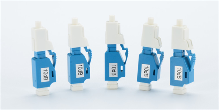
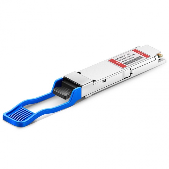
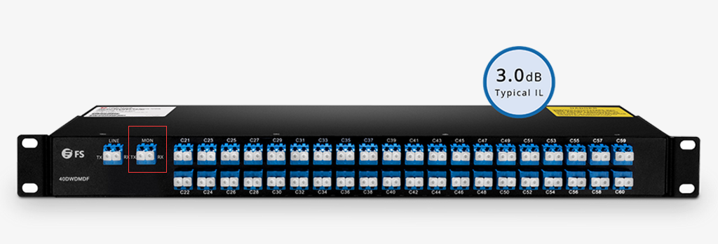
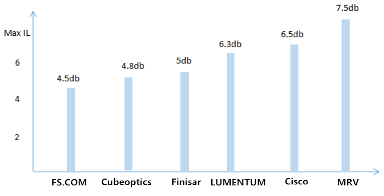
DWDM Muxs are the components that combine several different wavelengths so that they can be transferred on one fiber. And Mux is a passive device that cannot strengthen the light signals. Therefore, there is a big insertion loss of DWDM Mux. The lower the insertion loss is, the less network deployment cost is needed. Although Mux vendors are always endeavoring to reduce the insertion loss, there are still big differences between DWDM Muxs of many vendors. Here is a histogram to provide a direct-viewing comparison. From the graph, we can see the maximum insertion loss of FS.COM 40CH DWDM Mux is only 4.5dB.

40ch dwdm mux insertion loss comparison

DCM (Dispersion Compensation Module)

Dispersion compensation module is to fix the optical signals that have been deformed by chromatic dispersion. Therefore it is important to use at the receiver end to recover the signals by reshaping the optical pulse. This component also brings a good amount of insertion loss.

OADM (Optical Add/Drop Multiplexer)

OADM is another device that introduces insertion loss for DWDM networks. Since it allows individual or multiple wavelength channels to be added or dropped from an incoming link, as the signal pass from the common port to add/drop port or from the add/drop port to the common port, insertion loss occurs.

Except for the components that cause loss for the whole links, fiber optic cables also introduce loss which increases as the distance gets longer. Besides, in order to achieve balance signal power for receivers, designers often use EDFA to boost or add gain to optical signals on a fiber optic cable.

How to Calculate the Loss Budget of DWDM System?

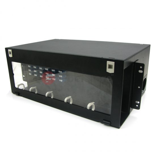
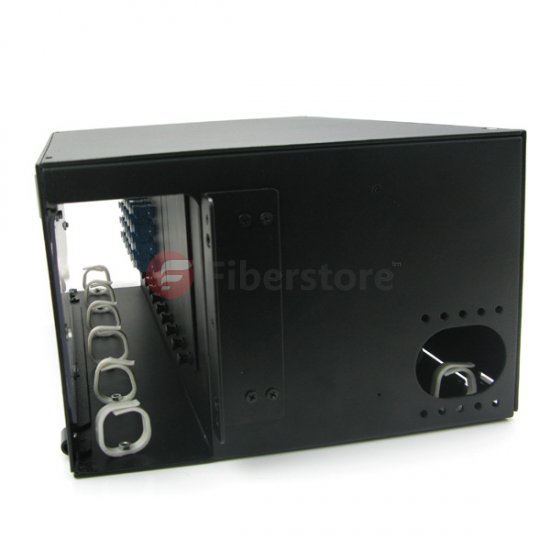
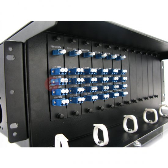
In order to illustrate the calculation process clearly, here takes a case from FS.COM as an example. This deployment solution is designed for a client in UK. The following picture just shows part of the solution design.

40ch dwdm mux solution

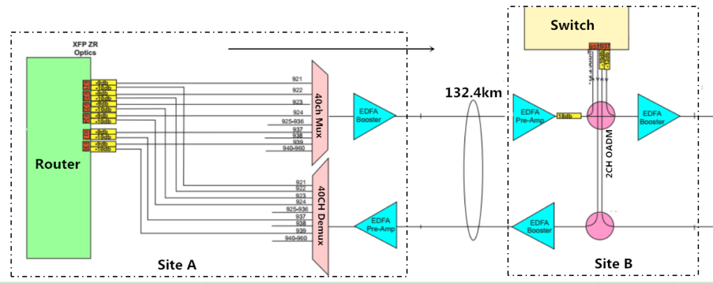
The distance of site A and site B is 132.4km. From the figure, we can see optical components used includes 40CH DWDM Mux/Demux, booster EDFA, Pre-amplifier, 2CH OADM, etc. And there are also optical attenuators which are not shown in the figure. Here is a chart indicating the loss or gain value of them which can be found on FS.COM website.

Components Insertion loss/Gain
40CH DWDM+MON 4.5dB
Booster EDFA 23dB
Pre-amp EDFA 26dB
Attenuator 0-30dB

Now let’s start to calculate the budget loss in this link. Considering the whole solution is so complicated that this calculation is just to give an example of calculating the budget loss between site A and site B. And the calculation starts from site A to site B unidirectional, as the arrow line shows.

  • The loss between the 40CH DWDM Mux and the router is -8.5dB, caused by the use of an optical attenuator.
  • Then the signals pass through the DWDM Mux, the output power is:-8.5dB-4.5dB =-13dB.
  • Since the booster EDFA gain is +23dB, the signal output power of this EDFA is: -13dB+23dB= +10dB.
  • Calculation of the fiber optic cable, the total loss is: -0.22dB/km x132.4km = -29.13dB. The input power of the pre-amp EDFA is: +10dB-29.13dB = -19.13dB.
  • The pre-amp EDFA gain is +26dB, then the output power of this EDFA is +6.87dB.
  • There is an attenuator placed after the pre-amp EDFA, the output power after the attenuator is: +6.87dB-18dB = -11.13dB.
  • The output power of the booster EDFA is: +23dB-11.13dB=+10.67dB. That’s the output power of site B.
Summary

For DWDM network system, how to control the power loss is important, which requires network designers calculate the budget loss before deploying the systems. This post gives an example from our client to calculate the loss in a DWDM network. FS.COM offers both necessary optical components and solutions for your networks. If you are interested, please contact us via sales@fs.com.

How to Optimize Your Network Performance with LC Assemblies?

High-density and compact data center cabling has become the consequent trend as the rapid development of fiber optic communication. Under this trend, LC assemblies, like the LC connector, LC adapter and LC attenuator, are more and more popular in the applications of cable television (CATV), fiber-to-the-home (FTTH) and dense wave division multiplexing (DWDM) Markets. Today this post intends to explore how to optimize network performance with LC assemblies.

LC Adapter for Easy Installation

It’s familiar to us that fiber optic adapters are used to connect fiber optic components with the same or different interfaces. Due to their ability to interconnect two connectors, they are widely applied in optical management systems. And nowadays there are various LC adapters available in the market for both single mode and multimode applications. Take the quad LC adapter for example, Quad LC adapters, designed for high-density applications, provide 4-position LC adapter solution in a traditional duplex SC footprint. The mating sleeve can connect four duplex or eight simplex LC fiber optic cables, saving more space and bring more flexibility.

Quad Plastic LC Fiber Optic Adapters

LC Attenuator for Better Transmission Quality

As we all know, signal strength needs to be reduced in some case. For instance, if a transmitter delivers too much light power, at the receiver end the power must be reduced by using fiber optic attenuator. Or it may degrade the bit error ratio (BER). LC attenuator is a type of widely applied fiber optic attenuator. It is designed to provide horizontal spectral attenuation over the full spectrum vary from 1260nm to 1620nm in single mode transmission. Therefore the LC attenuators can expand the capacity of optical networks by using the E-band (1400-nm window) for optical transmission.

LC fiber optic attenuator

LC HD Plus+ Fiber Cable for High Density Application

Designed with flexible “push-pull tab” uniboot connector, bend insensitive fiber and ultra-low insertion loss, LC HD plus+ fiber cables are the best choice for high-speed, high-bandwidth 1GbE and 10GbE networks in data centers. People with working experiences in data centers may know it’s not an easy task to add or remove one connector in numerous network cables. But with the push-pull tab uniboot connector, this problem can be solved perfectly. Firstly, the LC uniboot connector encloses two fibers firmly in a single cable, saving cable management space greatly. Secondly, the push-pull design enables connectors to be extracted or inserted into the port freely, which simplify the connectivity problems of limited access to the connector.

LC HD Plus+ Fiber Cable

LC Mux/Demux for More Flexibility in WDM Network

CWDM and DWDM Mux/Demux play an important role in combining data rate of different wavelengths over the same fiber cable to increase network capacity. No matter CWDM or DWDM Mux/Demux, there are several types of ports on them to ensure the normal function: channel port and line port. Of course, some Mux/Demux also have an expansion port and monitor port. A LC Mux/Demux means the LC Mux/Demux has LC connector for interfacing. It’s known to us that LC design is popular in fiber optic links. Mux/Demux with LC interface is easy to install and add WDM capacity to an existing network.

The following picture shows how to use two CWDM Mux/Demux at the same time to increase the wavelengths and expand the network capacity. The 8 CH and 4CH CWDM Mux/Demux are connected using the expansion port (LC interface).

stack-two-cwdm-mux

Summary

LC interface is the result of increased demands for smaller easier-to-use fiber connectivity. And a wide range of optical components with LC interface are widely used in optical networks. This article just introduces parts of them. Some other LC assembles such as optical transceivers, LC pigtails and LC adapter panels are available in Fiberstore. If you want to know more details, please visit FS.COM.

What is the Meaning of 100G Channels Networks to Service Providers

As the traffic demand continues growing, telecom network providers have planned introducing the newly developed coherent 100G transport software in their networks to satisfy the demand. History shows us that network service providers have made use of every stage of the new channel capacity available from equipment developers.

Fiberstore

Fiberstore

The figure below shows the timeline for increases in fiber link capacity operating provider’s networks. In early 1990s, a capacity of a few hundred Mbps per link and just on channel per strand of fiber inside a transport network was typical. As email was a new communication tool in the centre 1990s, the fiber capacity gradually increased to a couple Gbps, and this growth continued to deal with the demand that individuals needed to start accessing the web. Into the later 1990s, fiber capacity grew even larger with the deployment of 10 Gbps channels and WDM techniques to multiplex and amplify a small number of wavelengths (4-8) on a single fiber pair. In early 2000s, Internet usage became commonplace but networking kept pace using the introduction of DWDM techniques that could support 40, 80, or maybe more wavelengths allowing fiber capacities to be near Tbps. For MUX/DeMUX solutions with different DWDM wavelengths, please visit Fiberstore. This extensive fiber capacity increase helped the transport network support continually increasing user demands. In the late 2000s, the introduction of 40G channels gave the capability of the networks another boost. By 2010, video sharing on the web by applications such as YouTube along with other video when needed (VoD) services started to stress existing network capacity. The development of the fiber capacity to approximately 10 Tbps per fiber. This will address near term capacity requirements, but moving forward, cloud computing along with other bandwidth hungry applications will continue to consume network resources, and new optical techniques to increase channel capacity and optical link capacity is going to be introduced progressively.

Fiberstore

The coherent 100G PM-QPSK system selected by the industry is able to run at the same channel spacing (50 GHz) like a 10G commercial system does in existing networks, and so the 100G system can offer enough capacity for network service providers to support customer demands in the near term without a network overbuild. Using the new 100G system, service providers expect the cost per bit declines in the same rate as or perhaps a faster pace than the decline rate of serves prices service providers can charge their clients, so that providers are able to remain competitive.

Before telecom service providers introduce commercial coherent 100G software in their networks, normally a series of technology trials must be conducted in their existing networks to determine the performance of the new technology. The primary purpose of the technology trials would be to guarantee the 100G channel behaves well in existing fiber network infrastructures. Fiber routes within the field may have high transmission attenuation, high PMD values, multiple connections and splicing points, various fiber types, etc. While most lab experiments are conducted with fiber loop configurations, a linear configuration in field trials is much more preferred to mimic optical links in tangible networks. Field trials give network providers proper expectation for that performance of the systems, which will be installed in networks. Issues present in these trials may also be sent back somewhere developers for further product improvement. In a single field trial a 112 Gbps coherent channel transmitted over 1730 km deployed DWDM link in a service provider’s network, while using DWDM Multiplexer. A carrier suppressed RZ and differential PM-QPSK modulation format was utilized for the channel in the trial. The trial results show that the coherent 100G channel has the capacity to serve long term routes. The plug and play performance of the equipment and robustness to chromatic dispersion and PMD impairments was demonstrated in the trial. Co-propagating the 100G channel with adjacent 10 Gbps signals without touching the fiber infrastructure proved one viable migration road to next generation networks. It’s a requirement for service providers to maintain the networks scalable and cost-effective while increasing channel capacity and fiber ability to have next-gen multi-terabit networks.

In another field trial a real-time, single carrier, coherent 100G PM-QPSK upgrade of the existing 10G/40G terrestrial system was demonstrated inside a service provider’s network. The field experiment shows the performance of the 100G channel sufficient for error-free operation after FEC over installed 900 km and 1800 km fiber links. The experiment proves that flexible and seamless 100 Gps channel upgrades to existing 10G and 40G DWDM systems are possible and practical.

Yet another coherent 100G channel field trial was performed on dispersion shifted fiber (DSF) links. The trial involved eighty 127 Gbps channels propagating on a deployed fiber link. L-band specturn was used to avoid zero dispersion reason for specturn, differnet from using C-band for SMF or NZDSF for additional common cases. The 100G channels, with 50 GHz channel spacing, traveled over 458 km DSF successfully with L-band EDFA only. Sufficient Q-margins remained as left for the 80 channels following the 458 km transmission. This field trial demonstrated that a 10 Tbps calss capacity DWDM product is feasible underneath the condition of small local dispersion by deploying coherent detection and high overhead (20%) coding gain FEC. This trial represented the highest fiber capacity in the field at the time the trial was conducted.

The reason for introducing 100G channels into transport networks is to carry large IP data traffic across IP networks, therefore, an “end-to-end” transport trial, i.e. an entire data transport trial from data equipment to data equipment, using a coherent 100G channel transmission over a long distance, is particularly meaningful to service providers. One such field trial, which involved a worldwide network company, a data equipment developer, a transport equipment developer, and a client interface developer, continues to be reported. In this trial a 112 Gbps single carrier real-time coherent PM-QPSK channel from a transponder carried native IP packet traffic over 1520 km field deployed fiber, with 100GbE router cards and 100G CFP interfaces. This trial shows the feasibility of interoperability between multi-suppliers’ equipment for 100G transport. This field trial, which fully emulated an operating near-term deployment scenario, confirmed that all key components required for deployment of 100GbE technology are maturing at the time the trial was conducted (early 2010).

Fiberstore

The detailed configuration of the trial is shown in the figure. A 10GbE test set generates 10GbE traffic for Router 1 and also the test set can be used for analyzing packet throughput too. Another router (Router 2) is used to accept a GbE signal containing a video signal using a video encoder and to send the recording signal to some video display via a video decoder following the signal transverses the trial path. Router 2 connects to Router 1 with another 10GbE link, containing the video traffic. Router 1 routes both 10GbE data streams to one of the 100GbE cards and routes back the 10GbE data streams form the other 100GbE card towards the corresponding 10GbE ports. The 100G CFP interfaces are used to connect 100GbE cards and the 100G transponder. The transmitter port of the CFP in the first 100GbE card is connected to the receiver port of the CFP in the transponder and also the receiver port of the second 100GbE card is linked to yhe transmitter port from the CFP in the transponder. The receiver port from the CFP in the first 100GbE card and also the transmitter port of the CFP in the second 100GbE card are of a fiber jumper (fiber patch cable) to shut the loop. The CFP transponder sends the 112 Gbps signal towards the fiber route-equipped having a long haul DWDM system. Both directions of the inline amplifiers have been used for the trial to save on equipment needed.

With these successful 100G system field trials, telecom network providers and other network operators have been convinced that the only optical carrier PM-QPSK with coherent detections is easily the most promising 100G channel solutions, at least for the time being. Now commercial 100G systems are for sale to the customers of the equipment developers and the customers are likely to enjoy the ten times fiber capacity begin their networks.


Customized Empty 4RU Rack Chassis

The Fiberstore company can offer customized empty 4RU rack chassis to hold 12 pieces of standard size LGX cassettes now. They can also provide the custom LGX cassettes to complete this entire solution for space saving and high-density applications. Here are some finished products for example.

Fiberstore

Fiberstore

Fiberstore

Fiberstore

The specifications are described in the figure below.

Fiberstore

Fiberstore can offer various customized chassis on customers’ requirements, for example:

  • 1RU rack mount chassis that hold 2 pieces of small size LGX cassettes
  • 1RU rack mount chassis that hold 4 pieces of small size LGX cassettes
  • 4RU rack mount chassis that hold 12 pieces of standard size LGX cassettes

This is just an iceberg of custom cases that Fiberstore provides. They could make it beyond what you can imagine!

Contact Fiberstore sales now at sales@fiberstore.com and tell them what you want!
They’ll find the info you’re looking for and respond to your inquiry within one business day.


About Fiberstore:
Fiberstore is now the largest company who can supply all kinds of solutions for WDM optical networking systems, including CWDM, DWDM, MUX & DEMUX, OADM, etc.. The 4RU rack chassis is only a little part of their products. You can find whatever you want by just visiting the website (fiberstore.com).

FS.COM Supply 100GHz DWDM Mux Demux

DWDM Mux and DWDM Demux are designed to multiplex DWDM channels into one or two fibers. 100GHz DWDM Mux Demux is used to provide 100GHz transport solution for DWDM networking system. The common configuration is 4, 8, 16 and 32 channels, and we also have 40 and 96 channels. They are available in plug-in module and standalone 19″ 1RU or 2RU rack mount. These DWDM modules passively multiplex the optical signal outputs from 8 or more electronic devices, send them over a single optical fiber and then de-multiplex the signals into separate, distinct signals for input into electronic devices at the other end of the fiber optic link. We provide option of DWDM expansion port, monitor ports, 1310nm wideband port for existing 1310nm equipment.

AWG DWDM Modules – Planar Technology
FS.COM Thermal Arrayed Waveguide Grating (TAWG) DWDM modules are part of a series of high performance products based on silica-on-silicon planar technology. Our TAWG DWDM modules are designed for use within the C-band release of DWDM system. To decrease the power dissipation of the devices in different environmental conditions, the AWG package is special designed with selection of reliable thermal plastic with low thermal conduction, and the AWG operating temperature is controlled by using foil resist heater or Peltier TEC with thermistor temperature sensor.

100GHz DWDM Mux Demux

FS.COM 100GHz DWDM Mux Demux Solution
We supply common configuration 8, 16, 40 and 96 channels which is available in plug-in module and standalone 19″ 1RU/2RU rack mount. FS.COM provide option of DWDM expansion port, monitor ports, and 1310nm wideband port for existing 1310nm equipment. DWDM transceivers from FS.COM are together used in a cost effective way. DWDM is a proven technology, which offers flat channel bandwidth, flexible channel configuration, low insertion loss and high isolation. Modules are available on the C bands, ITU 100GHz grid at channel spacing of 100GHz.

QQ截图20171017150426

DWDM MUX and DEMUX Types
1. DWDM MUX DEMUX with Monitor Port
Many technicians will add a monitor port on DWDM MUX/DEMUX for better network monitoring and management. If you choose a single-fiber DWDM MUX DEMUX, the monitor port should be a simplex fiber optic port. For dual-fiber WDM MUX DEMUX, you can add a duplex monitor port for the whole network monitoring, or just add a simplex port for MUX or DEMUX monitoring.

1

2. DWDM MUX DEMUX with Expansion Port
Expansion port added on DWDM MUX DEMUX is really useful. If you installed a DWDM network which just using several of the DWDM wavelengths, you can use this expansion port to increase the network capacity by connecting the expansion port with the line port of another DWDM MUX DEMUX supporting different wavelengths. Then the network of this CWDM network can be increased easily.

QQ截图20171017150306

3. DWDM MUX DEMUX with 1310 Port
The 1310nm port is used in some legacy networks and sometimes as a return path. If an existing legacy network is using 1310nm port and they have exhausted all fibers and are looking for ways to increase their network capacity they can add in other DWDM wavelengths on to the same fiber while still allowing the use of the 1310nm port. Meanwhile, it can carry LR optics, LX optics etc.

3

FS.COM, as a 3rd party OEM manufacturer, we supply various 100GHz DWDM MUX DEMUX. Customer can select DWDM wavelength from ITU Grid C-Band C15 to C62. Customer can select LC/UPC, LC/APC, SC/UPC, SC/APC, FC/UPC, FC/APC, ST/UPC, ST/APC etc as connectors. Customer can select plug-in module or 1RU rack mount chassis as housing. Customer can add monitor port, expansion port and 1310 port. As a professional optical communication products manufacturer, we also supply CWDM MUX, 100G DWDM Muxponder, and FMT DWDM Optical Transport Network System.

Overview of CWDM Mux and DWDM Multiplexer

As the CWDM Mux/demux and DWDM mux/demux goods are playing an even more and more important role inside the data transmission field, today organic beef focus on the key options that come with CWDM mux and DWDM mux first.

As everybody knows, the CWDM Mux / demux module is based on dielectric thin-film technology designed for integration in low cost Metro and Access networks. These include applications such as fiber to the home, business or curb. The module enables 4 or 8 channels to be either combined (added) or separated (dropped). The fileters operate with a channel spacing of 20nm corresponding to standard CWDM wavelengths. CWDM Mux Demux module is a device to allow multiple optical signals at different wavelengths to pass through a single optical fiber strand. The common configuration of CWDM mux/demux module is 2CH, 4CH, 8CH, 16CH, 18CH CWDM mux/demux module. 3 Single fiber or dual fiber connection for CWDM Mux/demux are available. FiberStore’s CWDM modules has low insertion loss, high channel isolation, flat passband. Additional filters, to enable cascading of devices, or addition of 1310nm or other wavelength, can also be included in the module.

The CWDM mux products always own these following features:

> Passive, no electric power required. (MTBF ca. 500 years)
> Low insertion loss
> Accepts any data rate and any protocol on any port up to 10 Gbps, also 40 Gbps (DPSK, DQPSK) and 100 Gbps (DPQPSK)
> Fully transparent at all data rates and protocols from T1 to 40 Gbps
> 1RU Rack-mount chassis Low profile modular design
> Simple to install, requires no configuration or maintenance
> Low-cost transceivers applicable, existing equipment can still be used
> ISO 9001 manufacturing facility

And for the DWDM, which represents Dense Wavelength Division Multiplexing was created to multiplex DWDM channels into one or two fibers. This sort of products could make the optimum usage of your existing fiber optic infrastructure in an ideal way. It puts multiple signals together and sends them simultaneously along a fiber, simply with transmissions happening at different wavelengths, and also this turns an individual fiber to the virtual equal of a handful of fibers. It is really a good and also the most reasonable solution to date that will meet our increasing desires of large data transmissions. And also by using the impressive DWDM technique, it will transmit greater than 40 connections of numerous standards, data rates or protocols more than one common fiber optic link.

For the DWDM products, the DWDM mux products combine several data signals into one for transporting on the single fiber as the dwdm demux separate the signals into one for transporting on the single fiber as the dwdm mux products combine several data signals into one for transporting on the single fiber as the dwdm demux separate the signals on the opposite end. Each signal reaches a different wavelength, they cooperate with each other perfectly.

The common configuration of DWDM mux is 4, 8, 16 and 32 channels. These DWDM modules passively multiplex the optical signal outputs from 4 or maybe more electronic devices, send on them an
individual optical fiber and then de-multiplex the signals into separate, distinct signals for input into electronic devices in the opposite end with the fiber optic link.

The DWDM mux products always own these following features:

> Low insertion loss and high isolation.

> Simple to install, requires no configuration, and disassembles easily to clean.

> Fully transparent at all data rates and protocols.

> Completely passive, no power required, no cooling and so on.

As the very best China fiber optic products supplier, FiberStore Inc. provides lots of this sort of products which are reliable and economical. If you may well not find it on our website, you can call us to customize it to suit your needs. For standalone multiplexers, it could increase dual fiber link capacity up to 18 channels and could be combined with a lot of the CWDM GBIC, SFP, XFP, X2, XENPAK, SFP modules. It’s also super easy to make use of and install, and also have some common features because the DWDM mux. If you would like to know our fiber optic cables, optical cable price, indoor outdoor cable and more, please visit our website or contact us.

What Is The DWDM Mux Demux Working Principle?

From the wikipedia we know that“ In electronics, a Mux Demux is a device that selects one of several analog or digital input signals and forwards the selected input into a single line. A multiplexer of 2n inputs has n select lines, which are used to select which input line to send to the output. Multiplexers are mainly used to increase the amount of data that can be sent over the network within a certain amount of time and bandwidth .A mux is also called a data selector.”

An electronic multiplexer makes it possible for several signals to share one device or resource, for example one A/D converter or one communication line, instead of having one device per input signal.

Conversely, a demultiplexer (or demux) is a device taking a single input signal and selecting one of many data-output-lines, which is connected to the single input. A multiplexer is often used with a complementary demultiplexer on the receiving end.

DWDM Data Transmission Technology

Dense wavelength-division multiplexing (DWDM) revolutionized data transmission technology by increasing the capacity signal of embedded fiber. This increase means that the incoming optical signals are assigned to specific wavelengths within a designated frequency band, then multiplexed onto one fiber. This process allows for multiple video, audio, and data channels to be transmitted over one fiber while maintaining system performance and enhancing transport systems. This technology responds to the growing need for efficient and capable data transmission by working with different formats, such as SONET/SDH, while increasing bandwidth.

DWDM Fiber Working Principle

DWDM fiber works by combining and transmitting multiple signals simultaneously at different wavelengths on the same fiber. In effect, one fiber is transformed into multiple virtual fibers. So, if you were to multiplex eight OC -48 signals into one fiber, you would increase the carrying capacity of that fiber from 2.5 Gb/s to 20 Gb/s. Currently, because of DWDM, single fibers have been able to transmit data at speeds up to 400Gb/s.As for DWDM mux/demux, the common configuration is 2CH, 4CH, 8CH, 16 CH(16-Channel DWDM Mux/Demux), 32CH, 40CH channels.They are available in the form of Plastic ABS module cassette, 19” rack mountable box or standard LGX box. And no matter what kind of connectors, like FC, ST, SC, LC etc, all are available on our website: http://www.fs.com, and we also can mix connector on one device. We can provide you with the most suitable DWDM equipment.

Coarse wavelength division multiplexing(CWDM) multiplexer demultiplexer Developing

A WDM system uses a multiplexer at the transmitter to join the signals together, and a demultiplexer at the receiver to split them apart. With the right type of fiber it is possible to have a device that does both simultaneously, and can function as an optical add-drop multiplexer. In Fiberstore,I find the WDM including CWDM and DWDM equipment.Now,we work together to learn what is CWDM multiplexer demultiplexer.

Coarse wavelength division multiplexing (CWDM) is a method of combining multiple signals on laser beams at various wavelengths for transmission along fiber optic cables, such that the number of channels is fewer than in dense wavelength division multiplexing (DWDM) but more than in standard wavelength division multiplexing (WDM).

CWDM multiplexer demultiplexer Module is a flexible, low-cost solution that enables the expansion of existing fiber capacity. Coupled with highly reliable passive optics certified for environmentally hardened applications, the CWDM Mux/Demux lets operators make full use of available fiber bandwidth in local loop and enterprise architectures.

The CWDM multiplexer/demultiplexer is a universal device capable of combining nine optical signals into a fiber pair. It is designed to support a broad range of architectures, ranging from scalable point-to-point links to two fiber-protected rings.

The CWDM Mux/Demux is designed to interoperate with both the Wave Ready line of transponder and optical regenerator solutions as well as CWDM transponders and small form-factor pluggables (SFPs) used in widely available transmission equipment. With billions of field operating hours, the industryleading optical multiplexing technology offers unparalleled reliability and leading-edge performance.

CWDM Module Developing:

America’s CWDM module supports eight CWDM channel, in the near future is expected to be extended to 16 within the full spectrum wavelength. And launch of the CWDM system is said to have a comprehensive network management function, can to equipment remote monitoring, configuration, and the alarm. In addition, the CWDM has made the card into the recent popular GPON (gigabit PON) system. Recently, the American time warner has signed a long-term purchase agreement, includes: WavSystem of CWDM module will be used in New York, Ohio, the deployment of gigabit metropolitan area network.

In terms of optical fiber, the current us lang – development of full wave fiber and corning SMF28 – e fiber (g. 652 c) basically eliminated the water peak attenuation and macro bending loss, and other properties with conventional single-mode g. 652 optical fiber; Japan introduced two kinds of suitable for CWDM fiber of low water content, the fiber maximum eliminate residual fiber of OH – ions, reduce the transmission loss. The use of these optical fiber, is expected to greatly promote the wide popularity of CWDM technology, especially in the application of long distance communication.

In terms of optical fiber, the Japanese launched two suitable for CWDM fiber of low water content. The fiber in the utmost elimination of fiber OH ions residue, reduce the transmission loss. In addition, corning, companies such as lucent also produce optical fiber low water content. The use of these optical fiber, is expected to greatly promote the wide popularity of CWDM technology.