Optical Amplifier Used in CATV Transmission Network

CATV technology has matured steadily over the past several years, and has expanded into diverse applications. However, as the quick expansion in technology and services, it’s important to improve CATV network component performance for higher visual and audio signals transmission. Optical amplifier for CATV application is the key element in such transmission. This post intends to give a clear introduction of optical CATV amplifier and its application in CATV transmission.

Introduction to CATV Amplifier

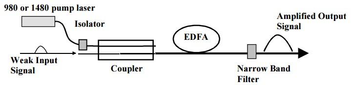
CATV amplifier is also a type of EDFA (Erbium Doped Fiber Amplifier) amplifier which is the most popular optical amplifier in optical network communications. It is mainly used to amplify damped TV signals (compensation for loss) for improved signal quality before sending them to each subscriber. Moreover, CATV amplifiers not only amplify the signal, but also amplify the noise on the line, and bring some return loss. That’s why a quality CATV amplifier price is a little high, because it can provide better performance for the whole network transmission.

Why CATV Amplifier Is Needed?

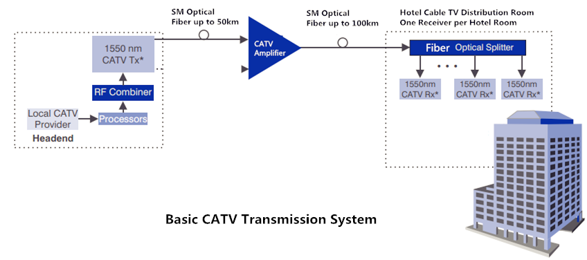
As we all know, CATV network is a multi-channel TV system to transmit high quality video and sound signal from a large number of digital or analog broadcast television and radio channel via fiber optic cable or coaxial cable. CATV amplifier often acts as booster optical amplifier in this system to get satisfying transmission effect. The following picture illustrates a basic long haul CATV transmission system using EDFA amplifier.

catv amplifier 1

In most cases, the satellite providers deliver high quality digital video and audio to users’ home depending on the users’ equipment. However, the signal incoming cable feed is connected to more than one equipment with use of optical splitters. And if the incoming signal gets fragmented and rerouted, the overall speed and quality will be worse. Under this condition, an optical amplifier can be used to boost the signal power and help users get better services.

CATV Amplifier in Long-Haul CATV Transmission System

As have mentioned above, a basic long-haul CATV communication link consists of head end, transmitter, receiver, optical amplifier, and sometimes fiber splitter is also needed in this type of transmission network. The head end receives TV signals off the air or from satellite feeds, and supplies them to the transmission system. The optical splitters are often utilized in a poin-to-multipoint configuration. Here are two CATV fiber network cases using CATV booster amplifier.

Case one

This is a point-to-multipoint medium size private CATV network. In the head end, the transmitter receives signals from the RF combiner on the 1310nm or 1550nm wavelength. Then the signals split into several parts and are received by the CATV receiver. Finally, all the signals are amplified by the CATV amplifier and sent to the subscriber.

catv amplifier 2

Case two

In the above application case, the optical amplifier lies behind the CATV receiver, but in this case, it’s a little different.

catv amplifier 3

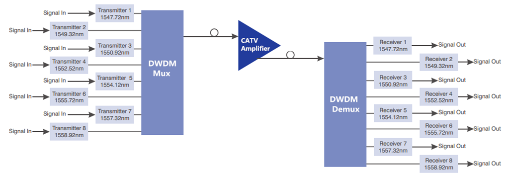
As we can see from the graph, the CATV amplifier lies in the front of the receiver to boost the transmission distance longer. Except for that, this transmission network also deploys two DWDM Mux/Demux to multiply the eight different wavelengths into one fiber for better transmitting. Please note that this graph just illustrates part of the long-haul CATV system.

Conclusion

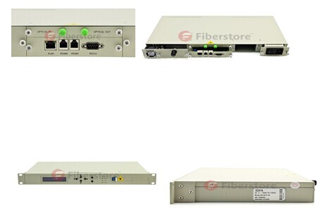
CATV amplifiers are used to boost the quality of optical signals and improve the speed and reliability of the services that users get. FS.COM offers various CATV amplifiers with different values and CATV optical transmitter. All of them are high quality. If you are interested, please contact us via sales@fs.com.

Introduction of EDFA

Before talking about Erbium-doped fiber amplifier (EDFA), we must have a simple understanding about optical amplifier (OA). OA is a device that amplifiers an optical signal directly, without the need to first convert it to an electrical signal. It is an important component in optical communication. There are usually 3 different types of OA, including erbium-doped fiber amplifier (EDFA), semiconductor optical amplifier (SOA) and Raman amplifier. EDFA is just one type of OA but plays an important role in a long-haul optical fiber communication. Now I’d like to make a detailed introduction of EDFA.

EDFA is an optical repeater device. It is usually used to improve the intensity of optical signals being carried through a fiber optical communication system. An optical fiber is doped with the rare earth element erbium so that the glass fiber could absorb light at one frequency and emit light at another frequency. With its features of high power transfer efficiency and large dynamic range, as well as low noise figure and polarization independent, it is an ideal solution for Wavelength Division Multiplex (WDM) applications and long-haul applications. In addition, a particular advantage of EDFA is its large gain bandwidth, which is typically tens of nanometers and thus actually more than enough to amplify data channels with the highest data rates.

EDFA sample

Now let us learn the basic principle of EDFA. EDFA is a high gain amplifier. It usually has two used pumping bands 980nm and 1480nm. This action amplifies a weak optical signal to a higher power, effecting a boost in the signal strength. The 980nm band has a higher absorption cross-section and is generally used where low-noise performance is required. The absorption band is relatively narrow so that wavelength stabilised laser sources are typically needed. The 1480nm band has a lower, but broader, absorption cross-section and is generally used for higher power amplifiers. In practice, a combination of 980nm and 1480nm pumping bands is usually used in EDFA.

The following picture shows us the working principle of EDFA. In optical fiber communication system, a relatively high-powered beam of light is mixed with the input signal using a wavelength selective coupler. The input signal and the excitation light must be at different wavelengths. The mixed light is guided into a section of fiber with erbium ions included in the core. This high-powered light beam excites the erbium ions to their higher-energy state. When the photons belonging to the signal at a different wavelength from the pump light meet the excited erbium atoms, the erbium atoms give up some of their energy to the signal and return to their lower-energy state. A significant point is that the erbium gives up its energy in the form of additional photons which are exactly in the same phase and direction as the signal being amplified. So the signal is amplified along its direction of travel only. Thus, all of the additional signal power is guided in the same fiber mode as the incoming signal. There is usually an isolator placed at the output to prevent reflections returning from the attached fiber. Such reflections disrupt amplifier operation and in the extreme case can cause the amplifier to become a laser.

principle of EDFA

By this blog, we have learnt that what is EDFA and its basic principle. If you have any requirements, welcome to visit Fiberstore.com or contact us over sales@fiberstore.com. Fiberstore is a professional supplier in this field. It can offer EDFA for you with high quality and competitive price.

Introduction of the Transients in Optical WDM Networks

A systems analysis continues to be completed to consider dynamical transient effects in the physical layer of an Optical WDM Network. The physical layer dynamics include effects on different time scales. Dynamics from the transmission signal impulses possess a scale of picoseconds. The timing recovery loops in the receivers be employed in the nanoseconds time scale. Optical packet switching in the future networks will have microsecond time scale. Growth and development of such optical networks is yet continuing. Most of the advanced development work in optical WDM networks is presently focused on circuit switching networks, where lightpath change events (for example wavelength add/drop or cross-connect configuration changes) happen on the time scale of seconds.

It is focused on the dynamics from the average transmission power associated with the gain dynamics in Optical Line Amplifiers (OLA). These dynamics may be triggered by the circuit switching events and have millisecond time scale primarily defined by the Amplified Spontaneous Emission (ASE) kinetics in Erbium-Doped Fiber Amplifiers (EDFAs). The transmission power dynamics will also be influenced by other active components of optical network, for example automatically tunable Optical Attenuators, spectral power equalizers, or other light processing components. When it comes to these dynamics, a typical power of the lightpath transmission signal is recognized as. High bandwidth modulation from the signal, which actually consists of separate information carrying pulses, is mostly ignored.

14-nodes Ring WDMRing WDM networks implementing communication between two fixed points are very well established technology, in particular, for carrying SONET over the WDM. Such simple networks with fixed WDM lighpaths happen to be analyzed in many detail. Fairly detailed first principle models for transmission power dynamics exist for such networks. These models are implemented in industrial software allowing engineering design calculations and dynamical simulation of these networks. Such models could possibly have very high fidelity, but their setup, tuning (model parameter identification) and exhaustive simulations covering a variety of transmission regimes are potentially very labor intensive. Adding description of new network components to such model could need a major effort.


14-nodes Mesh WDMThe problems with detailed first principle models is going to be greatly exacerbated for future Mesh WDM networks. The near future core optical networks will be transparent to wavelength signals on a physical layer. In such network, each wavelength signal travels through the optical core between electronic IP routers around the optical network edge using the information contents unchanged. The signal power is attenuated in the passive network elements and boosted by the optical amplifiers. The lightpaths is going to be dynamically provisioned by Optical Cross-Connects (OXCs), routers, or switches independently on the underlying protocol for data transmission. Such network is basically a circuit switched network. It might experience complex transient processes of the average transmission power for every wavelength signal at the event of the lightpath add, drop, or re-routing. A mix of the signal propagation delay and channel cross-coupling might result in the transmission power disturbances propagating across the network in closed loops and causing stamina oscillations. Such oscillations were observed experimentally. Additionally, the transmission power and amplifier gain transients could be excited by changes in the average signal power because of the network traffic burstliness. If for some period of time the wavelength channel bandwidth is not fully utilized, this could result in a loss of the average power (average temporal density of the transmitted information pulses).

First circuit switched optical networks are already being designed and deployed. Fraxel treatments develops rapidly for metro area and long term networks. Engineering design of circuit switched networks is complicated because performance has to be guaranteed for all possible combinations of the lightpaths. Further, as such networks develop and grow, they potentially need to combine heterogenous equipment from a variety of vendors. A system integrator (e.g., Fiberstore) of such network might be different from subsystems or component manufacturer. This creates a necessity of developing adequate means of transmission power dynamics calculations which are suitable for the circuit switched network business. Ideally, these methods should be modular, independent on the network complexity, and use specifications on the component/subsystem level.

Fiberstore has technical approach to systems analysis that’s to linearize the nonlinear system around a fixed regime, describe the nonlinearity like a model uncertainty, and apply robust analysis that guarantees stability and gratifaction conditions within the presence of the uncertainty. For a user of the approach, there is no need to understand the derivation and system analysis technicalities. The obtained results are very simple and relate performance to basic specifications of the network components. These specifications are somewhat not the same as those widely used in the industry, but could be defined from simple experimentation using the components and subsystems. The obtained specification requirements may be used in growth and development of optical amplifiers, equalizers, optical attenuators, other transmission signal conditioning devices, OADMs, OXCs, and any other optical network devices and subsystems influencing the transmission power.

The Evolution of Optical Amplifiers For DWDM

With the requirements of longer transmission lengths, fiber optic amplifier have become an essential component in long-haul fiber optic networks. Semiconductor optical amplifier (SOA), EDFA optical amplifier, and DWDM system amplifiers relif the effects of dispersion and attenuation, allowing improved performance for long-haul optical systems.

EDFAs

The evolution of EDFA has significantly miniaturized the loss of optical fiber. However dispersion is severely affecting the performance of fiber-optic systems. The light signal is severely distorted by dispersion, due to which signal quality, data rate and distance covered are greatly lessened. Therefore the techniques for effectively controlling the dispersion become burning concern in these systems.

EDFAs allow information to be transmitted over longer distances without the need for conventional repeaters. The fiber is doped with erbium, a rare earth element, that has the appropriate energy levels in their atomic structures for amplifying light. EDFAs are designed to amplify light at 1550 nm. The device utilizes a 980 nm or 1480nm pump laser to inject energy into the doped fiber. When a weak signal at 1310nm or 1550nm enters the fiber, the light stimulates the rare earth atoms to release their stored energy as additional 1550 nm or 1310 nm light. This process continues as the signal passes down the fiber, growing stronger and stronger as it goes.

The photons amplify the incoming signal optically, boosting the wavelength, and avoiding almost all of the active components. The output power of the EDFA is large, and thus, fewer amplifiers may be needed in any given system design. The amplification process is independent of the data rate. Because of this benefit, upgrading a system means only changing the launch/receive terminals.

As demands for wider bandwidth grow there is a call for more efficient and reliable optical amplifiers. The usable bandwidth of an EDFA is only about 30 nm (1530 nm-1560 nm), but the minimum attenuation is in the range of 1500 nm to 1600 nm. The dual-band fiber amplifier (DBFA) solves the usable bandwidth problem. It is broken down into two sub-band amplifiers. The DBFA is similar to the EDFA, but its bandwidth ranges from about 1528 nm to 1610 nm. The first range is similar to that of the EDFA and the second is known as extended band fiber amplifier (EBFA). Some features of the EBFA include flat gain, slow saturation, and low noise. The EBFA can achieve a flat gain over a range of 35 nm which is comparable to the EDFAs. EBFAs have the advantage of reaching a slower saturation keeping the output constant even though the input increases.

DWDM System Amplifiers

The explosion of dense wavelength-division multiplexing (DWDM) applications make DWDM optical amplifiers an essential fiber optic system building block, also forced the fiber optic manufacturers to develop DWDM multiplexer and demultiplexer that can handle closely spaced optical wavelengths. Due to DWDM systems handle information optically rather than electrically, it is imperative that long-haul applications do not suffer the effects of dispersion and attenuation.

Raman amplifier has been found to be an attractive candidate for DWDM system. Improved systems and methods for optical amplification of DWDM signals are provided by FiberStore.

Technology Of Fiber Optic Amplifiers

In fiber optic communication, the visible-light or infrared (IR) beams carried by a fiber are attenuated as they travel through the material. Then there comes to the fiber optic amplifier which is used to compensate for the wakening of information during the transmission.

Amplifiers are inserted at specific places to boost optical signals in a system where the signals are weak. This boost allows the signals to be successfully transmitted through the remaining cable length. In large networks, a long series of optical fiber amplifiers are placed in a sequence along the entire network link.

Common fiber optical amplifiers include Erbium-Doped Fiber Amplifier (or EDFA Optical Amplifier), Raman fiber amplifier, and silicon optical amplifier (SOA). Erbium doped fiber amplifier is the major type of the fiber amplifier used to boost the signal in the WDM fiber optic system, as we know it is WDM that increase the capacity of the fiber communications system and it is the erbium-doped fiber amplifier that makes WDM transmission possible. Fiber amplifiers are developed to support Dense Wavelength Division Multiplexing (DWDM) which is called DWDM EDFA amplifier and to expand to the other wavelength bands supported by fiber optics.

There are several different physical mechanisms that can be used to amplify a light signal, which correspond to the major types of optical amplifiers. In doped fibre amplifiers and bulk lasers, stimulated emission in the amplifier’s gain medium causes amplification of incoming light. In semiconductor optical amplifiers (SOAs), electron-hole recombination occurs. In Raman amplifiers, Raman scattering of incoming light with phonons in the lattice of the gain medium produces photons coherent with the incoming photons. Parametric amplifiers use parametric amplification.

When light is transmitted through matter, part of the light is scattered in random directions. A small part of the scattered light has frequencies removed from the frequency of the incident beam by quantities equal to the vibration frequencies of the material scattering system. Raman fiber optic amplifiers function within this small scattering range. If the initial beam is sufficiently intense and monochromatic, a threshold can be reached beyond which light at the Raman frequencies is amplified, builds up strongly, and generally exhibits the characteristics of stimulated emission. This is called the stimulated or coherent Raman effect.

EFDA fiber optic amplifier functions by adding erbium, rare earth ions, to the fiber core material as a dopant; typically in levels of a few hundred parts per million. The fiber is highly transparent at the erbium lasing wavelength of two to nine microns. When pumped by a laser diode, optical gain is created, and amplification occurs.

Silicon or semiconductor optical amplifier functions in a similar way to a basic laser. The structure is much the same, with two specially designed slabs of semiconductor material on top of each other, with another material in between them forming the “active layer”. An electrical current is set running through the device in order to excite electrons which can then fall back to the non-excited ground state and give out photons. Incoming optical signal stimulates emission of light at its own wavelength.

Fiber optic repeater also can re-amplify an attenuated signal but it can only function on a specific wavelength and is not suitable for WDM systems. That is the reason why optical amplifiers plays a much more important role in communication systems.