Basic Knowledge About Fiber Optic Attenuator

It seems to be a commonplace for us to use an amplifier in fiber optic transmission which helps to improve signal electricity. However, it may occur sometimes that there is just too much light delivering through a fiber optic receiver and should better be reduced. In this case, a component known as fiber optic attenuator can help to reduce the power level of the signal. This article will focus on describing the fiber optic attenuator in details from the perspective of its types and applications.

What Is Fiber Optic Attenuator?

A fiber optic attenuator, generally known as optical attenuator, is a passive device used to reduce the power level of an optical signal. It can be adopted in both free space and in an optical fiber. Besides, to employ a fiber optic attenuator in single-mode long-haul application contributes to decreasing the chance of optical overload at the receiver.

By means of absorption, reflection, diffusion, scattering, deflection, diffraction and dispersion, etc, the fiber optic attenuator works efficiently to reduce the power of the signal. Optical attenuators usually function by absorbing the light, that resembles sunglasses absorb extra light energy. There exists a working wavelength range in which they absorb the light energy equally. They should not reflect the light since that could cause unwanted back reflection in the fiber system.

The Types of Fiber Optic Attenuator

There are a number of different forms of fiber optic attenuators by various classified methods, but basically, fixed attenuators and variable attenuators serve as the most common types that we can find in the market.

Fixed Attenuator

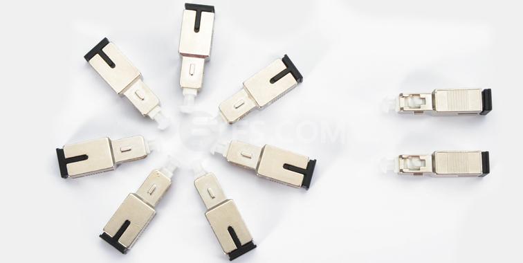
Fixed attenuator, as the name of which has indicated clearly, is designed to have an unchanging level of attenuation. It can theoretically be designed to provide any amount of attenuation that is desired. Fixed attenuator are typically used for single-mode applications and it consists of two groups: in-line type and connector type. In-line type appears like an ordinary fiber patch cable with a fiber terminated by two connectors. Connector type attenuator looks like a bulk head fiber connector, which has a male end and a female end as well. Fixed attenuator mates to regular connectors of the identical type such as FC, ST, SC and LC. The picture below shows a fixed male-female-SC/UPC SM 10dB fiber optic attenuator.

fixed attenuator

Variable Optical Attenuator

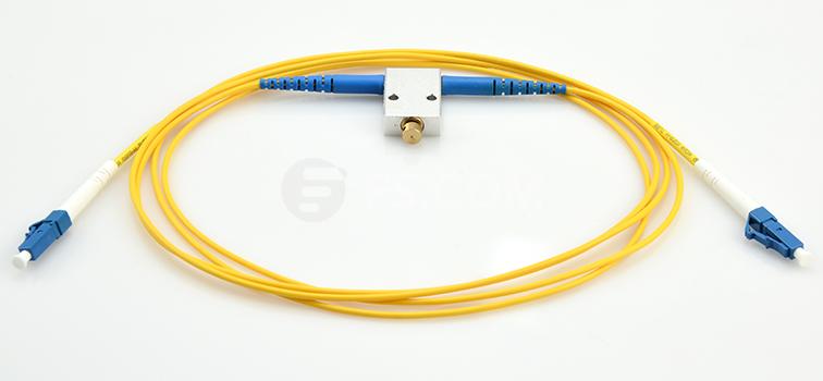
Variable optical attenuators generally use a variable neutral density filter. It has advantages of being stable, wavelength insensitive, mode insensitive, and offering a large dynamic range. Variable optical attenuator is generally used for testing and measurement, but it is also widely adopted in EDFAs (Erbium-Doped Fiber Amplifier) for equalizing the light power among different channels. Basically, there are two types of variable attenuators: stepwise variable attenuator and continuously variable attenuator. Stepwise variable attenuator can change the attenuation of the single in known steps such as 0.1 dB, 0.5 dB or 1 dB. Continuously variable attenuator produces precise level of attenuation with flexible adjustment. Thus, operators are able to adjust the attenuator to accommodate the changes required quickly and precisely without any interruption to the circuit. The following picture shows LC/UPC to LC/UPC variable fiber optic VOA in-line attenuator 0-60 dB.

variable optical attenuator

The Applications of Fiber Optic Attenuator

Fiber optic attenuator can be used to test power levels margins by temporarily adding a calibrated amount of signal loss. Besides, it is often installed permanently to properly match transmitter and receiver levels. And the sharp bends stress optic fibers and can cause losses.

Conclusion

From what we introduced above, you may have had a better understanding of the basic elements related to fiber optic attenuators. As an essential device in fiber optic transmission, it plays an indispensable role in controlling the power level of the optical signal. Those basic knowledge mentioned above may help provide a guideline to select the right fiber optic attenuator that matches the required applications precisely.

DO You Know Variable Optical Attenuator?

Optical Attenuator is one part of passive optical components. It’s widely used in fiber optic communications to reduce optical fiber power at a certain level. Variable optical attenuator is one of optical attenuator. Now I would like to introduce some basic knowledge of variable optical attenuator in this blog.

what is Variable Optical Attenuator?

Variable Optical Attenuator (VOA) is a double window (1310/1550nm) of passive optical components. Variable optical attenuator could continually and variably attenuate the light intensity in the optical fiber transmission. Variable optical attenuator cable could help simulate distance or actual attenuation in the fiber optic testing work by inserting a calibrated attenuation into the link. By using the variable optical attenuator (VOA), technicians could verify the power margin received by testing the fiber optic link power budget. Fiber optic VOA can help the user vary the light power injected from a light source into the optical fiber.

VOA type

Principle of Variable Optical Attenuator

The power reduction is done by such means as absorption, reflection, diffusion, scattering, deflection, diffraction, and dispersion, etc. Variable optical attenuator usually works by absorbing the light, like sunglasses absorb the extra light energy. It typically gets a working wavelength range in which they absorb the light energy equally. They should not reflect the light since that could cause unwanted back reflection in the fiber system. Or by scattering the light such as an air gap. Another type of attenuator utilizes a length of high-loss optical fiber. It operates upon its input optical signal power level in such a way that its output signal power level is less than the input level.

Built-in Variable Optical Attenuator

Variable optical attenuator may be either manually or electrically controlled. A manual device is useful for one-time set up a system, and is a near-equivalent to a fixed attenuator, and may be referred to as an “adjustable attenuator”. In contrast, an electrically controlled attenuator can provide adaptive power optimization.

Attributes of merit for electrically controlled devices, include speed of response and avoiding degradation of the transmitted signal. Dynamic range is usually quite restricted, and power feedback may mean that long term stability is a relatively minor issue. Speed of response is a particularly major issue in dynamically reconfigurable systems, where a delay of one millionth of a second can be expected to result in the loss of large amounts of transmitted data. Typical technologies employed for high speed response include LCD, or Lithium niobate devices.

With this blog, we have learnt the basic knowledge of variable optical attenuator.  It is necessary to use in fiber optical communications. Fiberstore is a professional supplier of fiber optic communication solution. Variable optical attenuator is just one of PON(passive optical network) components. For more information about variable optical attenuator, welcome to visit our website or contact us over sales@fiberstore.com.

Introduction of the Transients in Optical WDM Networks

A systems analysis continues to be completed to consider dynamical transient effects in the physical layer of an Optical WDM Network. The physical layer dynamics include effects on different time scales. Dynamics from the transmission signal impulses possess a scale of picoseconds. The timing recovery loops in the receivers be employed in the nanoseconds time scale. Optical packet switching in the future networks will have microsecond time scale. Growth and development of such optical networks is yet continuing. Most of the advanced development work in optical WDM networks is presently focused on circuit switching networks, where lightpath change events (for example wavelength add/drop or cross-connect configuration changes) happen on the time scale of seconds.

It is focused on the dynamics from the average transmission power associated with the gain dynamics in Optical Line Amplifiers (OLA). These dynamics may be triggered by the circuit switching events and have millisecond time scale primarily defined by the Amplified Spontaneous Emission (ASE) kinetics in Erbium-Doped Fiber Amplifiers (EDFAs). The transmission power dynamics will also be influenced by other active components of optical network, for example automatically tunable Optical Attenuators, spectral power equalizers, or other light processing components. When it comes to these dynamics, a typical power of the lightpath transmission signal is recognized as. High bandwidth modulation from the signal, which actually consists of separate information carrying pulses, is mostly ignored.

14-nodes Ring WDM
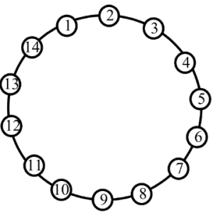
Ring WDM networks implementing communication between two fixed points are very well established technology, in particular, for carrying SONET over the WDM. Such simple networks with fixed WDM lighpaths happen to be analyzed in many detail. Fairly detailed first principle models for transmission power dynamics exist for such networks. These models are implemented in industrial software allowing engineering design calculations and dynamical simulation of these networks. Such models could possibly have very high fidelity, but their setup, tuning (model parameter identification) and exhaustive simulations covering a variety of transmission regimes are potentially very labor intensive. Adding description of new network components to such model could need a major effort.


14-nodes Mesh WDMThe problems with detailed first principle models is going to be greatly exacerbated for future Mesh WDM networks. The near future core optical networks will be transparent to wavelength signals on a physical layer. In such network, each wavelength signal travels through the optical core between electronic IP routers around the optical network edge using the information contents unchanged. The signal power is attenuated in the passive network elements and boosted by the optical amplifiers. The lightpaths is going to be dynamically provisioned by Optical Cross-Connects (OXCs), routers, or switches independently on the underlying protocol for data transmission. Such network is basically a circuit switched network. It might experience complex transient processes of the average transmission power for every wavelength signal at the event of the lightpath add, drop, or re-routing. A mix of the signal propagation delay and channel cross-coupling might result in the transmission power disturbances propagating across the network in closed loops and causing stamina oscillations. Such oscillations were observed experimentally. Additionally, the transmission power and amplifier gain transients could be excited by changes in the average signal power because of the network traffic burstliness. If for some period of time the wavelength channel bandwidth is not fully utilized, this could result in a loss of the average power (average temporal density of the transmitted information pulses).

First circuit switched optical networks are already being designed and deployed. Fraxel treatments develops rapidly for metro area and long term networks. Engineering design of circuit switched networks is complicated because performance has to be guaranteed for all possible combinations of the lightpaths. Further, as such networks develop and grow, they potentially need to combine heterogenous equipment from a variety of vendors. A system integrator (e.g., Fiberstore) of such network might be different from subsystems or component manufacturer. This creates a necessity of developing adequate means of transmission power dynamics calculations which are suitable for the circuit switched network business. Ideally, these methods should be modular, independent on the network complexity, and use specifications on the component/subsystem level.

Fiberstore has technical approach to systems analysis that’s to linearize the nonlinear system around a fixed regime, describe the nonlinearity like a model uncertainty, and apply robust analysis that guarantees stability and gratifaction conditions within the presence of the uncertainty. For a user of the approach, there is no need to understand the derivation and system analysis technicalities. The obtained results are very simple and relate performance to basic specifications of the network components. These specifications are somewhat not the same as those widely used in the industry, but could be defined from simple experimentation using the components and subsystems. The obtained specification requirements may be used in growth and development of optical amplifiers, equalizers, optical attenuators, other transmission signal conditioning devices, OADMs, OXCs, and any other optical network devices and subsystems influencing the transmission power.

Things About Fiber Optic Attenuators

An fiber attenuator uses a segment of attenuating fiber interposed in the optical path. The attenuating fiber is produced by using a solution doping technique to introduce transition or rare earth elements into the fiber’s core. The dopant reduces the transmission of the fiber. The degree of attenuation depends upon the material used as the dopant, the dopant level, and length of the attenuation segment. In a specific embodiment, an optical attenuator is provided having a first and second signal carrying optical fibers and an attenuating fiber segment, each of which has a core, a cladding substantially coaxial with the core, and a substantially planar end face. The attenuating fiber segment is fusion spliced between the first and second signal carrying optical fibers. In a second embodiment a portion of the cladding of the attenuating fiber is chemically etched.

How does a fiber attenuator work?

The power reduction are done by such means as absorption, reflection, diffusion, deflection, and dispersion, etc. Attenuators usually works by absorbing the light, like sunglasses absorb the extra light energy. Attenuators typically have a working wavelength range in which they absorb the light energy equally. They should not reflect the light since that could cause unwanted back reflection in the fiber system. Or by scattering the light such as an air gap. Another type of attenuator utilizes a length of high-loss optical fiber, that operates upon its input optical signal power level in such a way that its output signal power level is less than the input level.

Types Of Fiber Optic Attenuators

Optical attenuators can take a number of different forms and are typically classified as fixed or variable attenuators.

Fixed Attenuators Fixed attenuators have a fixed optical power reduction number, expressed in dB, such as 1dB, 5dB, 10dB, etc. A -3dB attenuator should reduce intensity of the output by 3 dB. Their applications include telecommunication networks, optical fiber test facility, Local Area Network(LAN) and CATV systems.

Fixed value attenuators are composed of two big groups: In-line type and connector type (or build out style). In-line type looks like a plain fiber patch cable, it has a fiber cable terminated with two connectors which you can specify types.

Connector type attenuator looks like a bulk head fiber connector, with a male connector interface on one end and a female interface connector on the opposite end. The connector style is typically fabricated with either air gap attenuation or doped fiber attenuation. It mates to regular connectors of the same type such as FC, ST, SC and LC. The female to female fixed attenuators work like a regular adapter. But instead of minimizing insertion loss, it purposely adds some attenuation. The male to female fixed attenuators work as fiber connectors, you can just plug in your existing fiber connector to its female side.

Variable Attenuators, the attenuation level can be adjusted, such as from 0.5 dB to 20dB, or even 50dB. Some variable attenuators have very fine resolution, such as 0.1dB, or even 0.01dB. This is critical for accurate testing. For precise testing purposes, engineers have also designed instrument type variable attenuators. These instrument type attenuators have high attenuation ranges, such as from 0.5 dB to 70dB. Variable attenuators are general used for testing and measurement, but they also have a wide usage in EDFAs for equalizing the light power among different channels.

The female to female variable attenuators are adjustable by turning a nut in the middle. The nut adjusts the air gap in the middle to achieve different attenuation levels. The in-line patch cable type variable attenuators work as regular patch cables, but your can adjust its attenuation level by turning the screw.

FiberStore supply a lot of fiber attenuators, such as FC, SC/APC, PC, UPC, MU, FC/APC, SC, LC/APC, LC attenuatorST fiber attenuator 850nm, etc. fixed value plug type fiber attenuators with different attenuation level, from 1dB to 30dB. If you would like to know VOA fiber optic price, please visit our website.

What is Optical Fiber Attenuators

An optical attenuator is a passive device that is used to reduce the power level of an optical signal. The attenuator circuit will allow a known source of power to be reduced by a predetermined factor, which is usually expressed as decibels. Fiber attenuators are generally used in single mode long-haul applications to prevent optical overload at the receiver.

Fiber Optical Attenuators typically come in two forms of packaging. The bulkhead optical attenuator can be plugged into the receiver receptacle. The inline attenuator resembles a patch cord and is typically used between the patch panel and the receiver.

The Principles of Optical Attenuators

Optical attenuators use several different principles in order to accomplish the desired power reduction. Fiber attenuators may use the gap-loss, absorptive, or reflective technique to achieve
the desired signal loss. The types of attenuators generally used are fixed, stepwise variable, and continuously variable.

Gap-Loss Principle

The principle of gap-loss is used in optical attenuators to reduce the optical power level by inserting the device in the fiber path using an in-line configuration. Gap-loss attenuators are used to prevent the saturation of receiver and are placed close to the transmitter. Gap-loss attenuators use a longitudinal gap between two optical fibers so that the optical signal passed from one optical fiber to another is attenuated. This principle allows the light from the transmitting optical fiber to spread out as it leaves the optical fiber. When the light gets to the receiving optical fiber, some of the light will be lost in the cladding because of gap and the spreading that has occurred.

The gap-loss attenuator will only induce an accurate reduction of power when placed directly after the transmitter. These attenuators are very sensitive to modal distribution ahead of the
transmitter, which is another reason for keeping the device close to the transmitter to keep the loss at the desired level. The farther away the gap-loss attenuator is placed from the transmitter, the less effective the attenuator is, and the desired loss will not be obtained. To attenuate a signal farther down the fiber path, an optical attenuator using absorptive or reflective techniques should be used.

Keep in mind that the air gap will produce a Fresnel reflection, which could cause a problem for the transmitter.

Absorptive Principle

The absorptive principle, or absorption, accounts for a percentage of power loss in optical fiber. This loss is realized because of imperfections in the optical fiber that absorb optical energy and convert it to heat. This principle can be employed in the design of an optical attenuator to insert a known reduction of power.

The absorptive principle uses the material in the optical path to absorb optical energy. The principle is simple, but can be an effective way to reduce the power being transmitted and received.

Reflective principle

The reflective principle, or scattering, accounts for the majority of power loss in optical fiber and again is due to imperfections in the optical fiber, which in this case cause the signal to scatter. The scattered light causes interference in the optical fiber, thereby reducing the amount of transmitted and received light. This principle can be employed in the planned attenuation of a signal. The material used in the attenuator is manufactured to reflect a known quantity of the signal, thus allowing only the desired portion of the signal to be propagated.

Now that we have looked at the principles behind the attenuator theories, we will discuss some of the types of fiber attenuators. We will examine fixed, stepwise variable, and continuously variable attenuators and when they should be used.

Types of Attenuators

Fixed attenuators are designed to have an unchanging level of attenuation. They can theoretically be designed to provide any amount of attenuation that is desired. The output signal is
attenuated relative to the input signal. Fixed attenuators are typically used for single-mode applications.

Stepwise variable attenuators

A stepwise variable attenuator is a device that changes the attenuation of the signal in known steps such as 0.1dB, 0.5dB, or 1dB. The stepwise attenuator may be used in applications dealing with multiple optical power sources—for example, if there are three inputs available, there may be a need to attenuate the signal at a different level for each of the inputs.

Conversely, the stepwise attenuator may also be used in situations where the input signal is steady, yet the output requirements change depending on the device that the signal is output to.

The stepwise attenuator should be used in applications where the inputs, outputs, and operational configurations are known.

Continuously variable attenuator

Continuously variable attenuator is an attenuator that can be changed on demand. These attenuators generally have a device in place that allows the attenuation of the signal to change as required. A continuously variable attenuator is used in uncontrolled environments where the input characteristics and output needs continually change. This allows the operator to adjust the
attenuator to accommodate the changes required quickly and precisely without any interruption to the circuit.

Calculating the attenuation value

In summary, there are many types of attenuators and many principles on which they work. The key to choosing the appropriate one is to understand the theory on which each operates and the application that the attenuator will be applied to. Of course, you also need to be able to determine the attenuator value in decibels required for your application.

In this example let’s assume that the maximum optical input power a fiber optic receiver can operate with is -6dBm. If the input power exceeds this power level, the receiver will be overloaded. The transmitter, which is located 10km from the receiver, has an output power of 3dBm. The loss for the 10km of optical fiber, including interconnections, is 5dB.

To calculate the minimum attenuation required to prevent the receiver from being overloaded, we need to subtract all the known losses from the output power of the transmitter as shown here:

Transmitter power (TP) = 3dBm
Receiver maximum optical input power (MP) = –6dBm
Total losses (TL) = 5dB
Minimum attenuation required = MP + TL – TP–6dBm + 5dB – 3dBm = –4dB

At a minimum, a 4dB attenuator is required. However, an attenuator with a larger value could be used as long as it did not over-attenuate the signal.

As the best Chinese fiber optic products supplier, FiberStore Inc. supply a range of fiber attenuators, fiber transceiver, plc splitter, optical fiber sale and more. If you would like to
purchase our products, please contact us.

How To Choose Fiber Optic Attenuators

Fiber attenuators are used in fiber optic communications to reduce optical fiber power at a certain level. Why do we need fiber attenuators? Bigger is better, right? Or so most people believe. Beginners in fiber optic technology are often confued with why optical attenuators are necessary to reduce light intensity. Aren’t we using amplifiers to increase the signal power level?

The truth is that too much light can overload a fiber optic receiver. Optical fiber attenuators are needed when a transmitter delivers too much light, such as when a transmitter is very close to the receiver.

How Does a Fiber Attenuator Work?

Optical Attenuators usually works by absorbing the light, such as a neutral density thin file filter. Or by scattering the light such as an air gap. They should not reflect the light since that could cause unwanted back reflection in the fiber system.

Another type of attenuator utilizes a length of high-loss optical fiber, that operates upon its input optical signal power level in such a way that its output signal power level is less than the input level. The power reduction are done by such means as absorption, reflection, diffusion, scattering, deflection, diffraction, and dispersion, etc.

What is the Most Important Feature Should a Fiber Attenuator Have?

The most important spec of an attenuator is its attenuation versus wavelength curve. Optical attenuators should have the same effect on all wavelengths used in the fiber system or at least as flat as possible. For example, a 3dB attenuator at 1500nm should also reduce the intensity of light at 1550nm by 3dB or as close as possible, this is especially true in a WDM (Wavelength Division Multiplexing) system.

Different Types of Attenuators

There are two functional types of fiber attenuators: plug style (including bulkhead) and in-line. A plug style attenuator is employed as a male-female connector where attenuation occurs inside the device, that is, on the light path from one ferrule to another. The types of fiber optic attenuators are based on the types of connectors and attenuation level. FiberStore supply a lot of fiber optic attenuators, like FC, SC/APC, ST, PC, LC, UPC, MU, FC/APC, SC, LC/APC, fixed value plug type fiber attenuators with different attenuation level, from 1dB to 30dB. An in-line attenuator is connected to a transmission fiber by splicing its two pigtails.

The principle of operation of attenuators are markedly different because they use various phenomena to decrease the power of the propagating light. The simplest means is to bend a fiber. Coil a patch cable several times around a pencil while measuring the attenuation with a power meter, then tape this coil. Then you got a primitive but working attenuator. Most fiber attenuators have fixed values that are specified in decibels (dB). They are called fiber optic fixed attenuator. For example, a -3dB attenuator should reduce intensity of the output by 3dB.

Manufacturers use various types of light-absorbing material to achieve well-controlled and stable attenuation. For example, a fiber doped with a transition metal that absorbs light in a predictable way and disperses absorbed energy as a heat. Variable fiber optic attenuators also are available, but they usually are precision instruments used in making measurements.

As the very best China fiber optic products supplier, FiberStore Inc. provides lots of this sort of products which are reliable and economical. If you may well not find it on our website, you can call us to customize it to suit your needs. We also supply PLC splitter, fiber transceiver, optical cable, if you would like to know how much does fiber optic cable cost, please visit our website.

Understanding Optical Attenuators

Optical fiber attenuators are used to reduce the power level of optical signal, either in free space or in an optical fiber. They are often used in optical communication systems where the optical signal is too strong and needs to be reduced, in which the attenuation, also called transmission loss, helps with the long-distance transmission of digital signals.

Optical attenuators can take a number of different forms and are typically classified as fixed or VOA attenuator. Fixed attenuators can be broken down into either build out style or incorporated into a patch cord. The build out variety is a small (~ 1.25 inch long) attenuator with a male connector interface on one end and a female interface connector on the opposite end. The build out style is typically fabricated with either air gap attenuation or doped fiber attenuation.

Fiber optic attenuators can be designed to use with various types of fiber optic connectors. Commonly used fiber optic attenuators are the female to male type, which is also called a plug fiber attenuator. Another type inline fiber optic attenuator is designed with a piece of fiber optic cable at any length and connectors are installed as the customers request. Fixed value fiber optic attenuators can reduce the optical light power at a fixed level, for example, a 10dB SC fiber optic attenuator will reduce the optical power 10dB and utilize a SC male to female attenuator. Variable fiber optic attenuators are with adjustable attenuation range. There are also attenuation fiber optic patch cables available, their function is the same as attenuators and are used inline.

Variable Attenuator (or ajustable fiber optic attenuator) is a need to provide different under construction decline. The reduction of precision devices for a wide variety of fiber optic transmission lines to carry out scheduled, the amount of light intensity attenuation. There are also handheld variable fiber optic attenuators which are used as test equipment.

Typical attenuation values are between 3 and 20 dB. It is used in optical systems where the optical power from a source is too high for the test equipment in use. Fixed plug type fiber attenuator provides a connector plug (male) and an adapter socket (female) to connect between fiber patch cord and fiber adapter. Fixed plug type optical attenuator introduces an in-line fixed loss that will reduce the source power to an acceptable detection level. The attenuation level should be stable with temperature and wavelength for a stable reliable system.

An optical attenuator uses a segment of attenuating fiber interposed in the optical path. The attenuating fiber is produced by using a solution doping technique to introduce transition or rare earth elements into the fiber’s core. The dopant reduces the transmission of the fiber. The degree of attenuation depends upon the material used as the dopant, the dopant level, and the length of the attenuation segment. In a specific embodiment, an optical attenuator is provided having a first and second signal carrying optical fibers and an attenuating fiber segment, each of which has a core, a cladding substantially coaxial with the core, and a substantially planar end face. The attenuating fiber segment is fusion spliced between the first and second signal carrying optical fibers. In a second embodiment a portion of the cladding of the attenuating fiber is chemically etched.

Wide range variable & inline fiber optic attenuator and the inline fiber optic attenuator are with more accurate attenuation compared with traditional connector type fiber optic attenuators. Variable optical attenuators from FiberStore are specifically designed for use in DWDM networks with individual channel source elements such as add drop multiplexer.