
By multiplexing separated wavelengths from multiple ports onto a single fiber in the network, coarse wavelength division multiplexing (CWDM) network increases fiber capacity at a low cost. And all the CWDM components are passive and do not need power, which requires lower investment than DWDM networks and make it popular. This article intends to explore how to calculate the power budget and link distance in CWDM network, offering more conveniences for your CWDM network deployment.
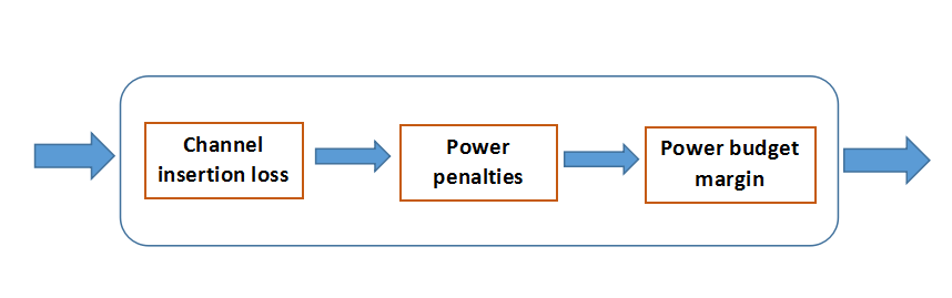
One important factor of network design, including various optical networks like DWDM and PON, is the optical power budget. Optical power budget is the amount of light available to make a fiber optic connection. The difference between the output power of the transmitter and the input power requirements of the receiver is referred to as the power budget. The power budget with various losses in an optical fiber, as shown in the picture below, is obtained by first determining the optical power emitted by the source, usually expressed in dBm, and subtracting the power (expressed in same units, e.g., dBm) required by the detector to achieve the design quality of performance (Receiver Sensitivity). Here is a common equation that can be used to calculate the power budget in a decided length fiber link.
Link Power Budget = Min Transmit Power – Min Receiver Sensitivity
When designing a CWDM network, power budget is often used to determine the maximum distance that a link can support. The transmission power budget is the difference between the optical transmitter output power and the receiver sensitivity. In order to explain the calculation process clearly, all the equations will be given an example for illustrating.
Power Budget = Tx Power – Rx Sensitivity.
Example one. A -2 dBm optical transmitter and a -25 dBm receiver provide a total transmission power budget of 23 dB.
Power Budget = Tx Power – Rx Sensitivity = -2 dBm – (-25 dBm) = 23 dB
As we all know, in a CWDM system, CWDM Mux/Demux, CWDM OADM and other components are common. And each one of them will introduce loss once added into the CWDM system. For example, when using a CWDM OADM in CWDM network, the point where a channel is dropped, added, or passed will cause a loss of signal strength. Therefore, when calculating power budget for a CWDM link, all losses must be added together. As shown in the following equation.
Power Budget = Tx Power – Rx Sensitivity – Losses
Example two. Here is a link A shown as below. There are four CWDM Mux/Demuxes and two CWDM SFP transceivers in this link. The Mux/Demux #1 and Mux/Demux #4 are 8-channel CWDM Mux/Demux. The left two is 4-channel CWDM Mux/Demux. Link A is the distance from CWDM SFP #1 and CWDM SFP#4. Each CWDM Mux/Demux has a low insertion loss. For instance, the insertion loss of the 8-channel CWDM Mux/Demux is less than 3.1dB (including connectors and adapters).
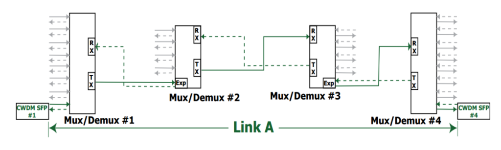
Here is the calculating process.
Power Budget = Tx Power – Rx Sensitivity – Losses
Tx Power = 2 dBm
Rx Sensitivity = -23 dBm
Losses = (8-channel Mux/Demux #1 loss) + (4-channel Mux/Demux #2 loss) + (4-channel Mux/Demux #3 loss) + (8-channel Mux/Demux #4 loss)
= 2.5 dB + 2.0 dB + 2.0 dB + 2.5 dB = 9.0 dB
Power Budget = Tx Power – Rx Sensitivity – Losses = 2 dBm – (-23 dBm) – 9.0 dB = 16 dB
After determining the power budget for a fiber link, we can use the value to calculate the maximum distance that the link can support. The calculation equation is shown as below.
Power Budget = Buffer Distance/Fiber Attenuation
Usually, a buffer of 2 dB is subtracted from the power budget to account for other factors that may affect the loss of transmission power. These factors include fiber aging, temperature, poor splice, etc. Fiber attenuation is the loss of signal strength as it travels through the fiber. The attenuation varies with the wavelength. Typical values are 0.2 to 0.35 dB/km.
Then we will calculate the maximum supported distance of link A in example two. Here we take the worst value for the fiber attenuation. The distance is:
Distance = (16 dB-2 dB)/0.35dB/km = 40km
The maximum supported distance of link A is 40km.
Knowing how to calculate the power budget and transmission distance can help engineers estimate the CWDM network deployment cost, and also can avoid some unnecessary problems in network design. This post gives a clear illustration to calculate them. Hope it would help you. In addition, FS.COM is a professional manufacturer and supplier of optical components. If you have any need, welcome to visit our website www.fs.com.