
Optical Circulators are microoptic devices and can be made with any number of ports but 3 and 4 port versions are most common. Also, it is common to build an asymmetric version where the last port does not circulate around to the first. While this saves some cost this is not the most important reason for doing it. If we make sure the last port does not circulate around to the first, we can use the device in systems where we do not need (or want) this feature. For example, if the input to the first port is directly connected to a laser we certainly don’t want spurious signals to be returned back into it.
One of the great attractions of optical circulators is the relatively low level of loss. Typical devices give a port-to-port loss of between 0.5 dB and 1.5 dB. Optical circulators are very versatile devices and may be used in many applications. For example, a bidirectional link consisting of two fiber strands (one for each direction) is multiplexed onto a single strand of fiber. This might be done to save the cost of fiber. Of course if you did something like this you would need to take particular care to minimise reflections on the link.
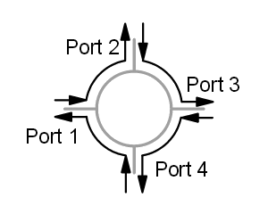
By itself there is no single, simple principle behind the optical circulator. Optical circulators are made of an assembly of optical components. There are many different designs but the key principle is like that of the optical isolator. The basic function of a circulator is illustrated in the figure below. Light entering at any particular port travels around the circulator and exits at the next port. Light entering at port 1 leaves at port 2, entering at port 2 leaves at port 3 and so on. The device is symmetric in operation around a circle.
Light travelling in one direction through a Faraday rotator has its polarisation rotated in one particular direction. Light entering the Faraday rotator from the opposite direction has its phase rotated in the opposite direction (relative to the direction of propagation of the light). Another way of looking at this is to say that light is always rotated in the same direction in relation to the rotator regardless of its direction of travel. This is complicated by the presence of unpredictable polarisation. We could filter the unwanted polarisation out but we would lose (on average) half our light in doing that—and often a lot more. So we separate the incident “ray” into two orthogonally polarised rays and treat each polarisation separately. The two halves of the ray are then re-combined before being output to the destination port.
Here is a figure showing a basic 3-port optical circulator. Its components function as following:
- Polarising Beam Splitter Cube: This device separates the input ray into two orthogonally polarised rays.
- Birefringent “Walk-off” Block: This is just a block of birefringent material cut at 45° to the optic axis. A ray incident at a normal to the air-crystal interface is split into two rays of orthogonal polarisation. The ordinary ray is not refracted and passes through unaffected. The extraordinary ray is refracted at an angle to the normal.
- Faraday Rotator and Phase Plate: This combination passes light in one direction completely unchanged! (In the figure this is the right-to-left direction.) In the opposite direction polarisation of incoming light is rotated by 90°. In the left-to-right direction the Faraday rotator imparts a phase rotation of 45° (clockwise) and the phase plate rotates the light another 45° (also clockwise). Thus we get a net 90° clockwise rotation. In the right-to-left direction the phase plate rotates the light in the same direction (in relation to the direction of the ray of light) as before, that is, anti-clockwise at 45°. The Faraday rotator however rotates the phase in the opposite direction (in relation to the direction of the ray) as it did before, that is, clockwise by the same 45°. That is the phase is rotated in the opposite direction . Thus there is no net change in polarisation. (Of course in practice there are losses due to reflections and imperfections in device manufacture.)
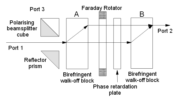
As shown in the 3-port optical circulator, light travels from Port 1 to Port 2 as following:
- 1. A ray input on Port 1 is split into two separate rays of orthogonal polarisations. The “ordinary” ray passes through without refraction but the orthogonally polarised “extraordinary” ray is refracted (upwards in the figure).
- 2. Both rays proceed from left-to-right through the Faraday rotator and phase retardation plates. Both rays are rotated through 90°.
- 3. The two rays then meet another birefringent walk-off block (block B) identical with the first. The effect of the phase rotation in the previous stage was to swap the status of the rays. The ray that was the ordinary ray in block A (and was not refracted) becomes the extraordinary ray in block B (and is refracted in block B). The extraordinary ray in block A (the upper path in the figure) becomes the ordinary ray in block B (and is not refracted in block B). The light is refracted and re-combined as shown. It is then output to Port 2.
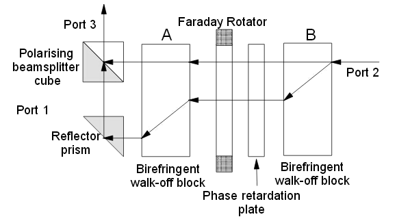
Coupling to fiber on input and output would normally use a lens of some kind. Typically a GRIN lens might be used here. The path from Port 2 to Port 3 is somewhat more involved:
- 1. Light entering from Port 3 is split in block B.
- 2. Travelling in the reverse direction the polarisation of both rays is unchanged.
- 3. Birefringent block A now passes the upper ray unchanged but shifts the lower one further away. 4. The two rays are then re-combined using the reflector prism and the polarising beamsplitter cube.
Note: If you only connect Ports 1 and 2, the optical circulator can be used as an Optical Isolator. Indeed if you leave out the beamsplitter cube and the reflector prism, you have an excellent (very low loss) polarisation independent isolator. A path from Port 3 to Port 1 can be constructed by adding additional components; however, for most applications this is unnecessary as we don’t want the connection from Port 3 to Port 1 anyway.
There are many ways to construct optical circulators (both 3 and 4 port). All of these ways use combinations of components and similar principles as those described above. The biggest problem with optical circulators is that the components must be manufactured to very close tolerances and positioned extremely accurately. This causes the cost to be relatively high. However, you could find cost-effective Optical Circulators in Fiberstore.
Article Source: http://www.fiberopticshare.com/passive-optical-components-optical-circulator.html