Choosing the Right MTP/MPO Cable: A Guide to Core Numbers

Choosing the right MTP/MPO cable ensures efficient and reliable data transmission in today’s fast-paced digital world. With the increasing demand for high-speed connectivity, it is essential to understand the importance of core numbers in MTP/MPO cables. In this guide, we will explore the significance of core numbers and provide valuable insights to help you decide when selecting the right MTP/MPO cable for your specific needs. Whether setting up a data center or upgrading your existing network infrastructure, this article will serve as a comprehensive resource to assist you in choosing the right MTP/MPO cable.

What is an MTP/MPO cable

An MTP/MPO cable is a high-density fiber optic cable that is commonly used in data centers and telecommunications networks. It is designed to provide a quick and efficient way to connect multiple fibers in a single connector.

MPO and MTP cables have many attributes in common, which is why both are so popular. The key defining characteristic is that these cables have pre-terminated fibers with standardized connectors. While other fiber optic cables have to be painstakingly arrayed and installed at each node in a data center, these cables are practically plug-and-play. To have that convenience while still providing the highest levels of performance makes them a top choice for many data center applications.

How Many Types of MTP/MPO cables

MTP/MPO cables consist of connectors and optical fibers ready to connect. When it comes to types, MTP/MPO fiber cables fall on MTP/MPO trunk cables and MTP/MPO harness/breakout cables.

MTP/MPO trunk cables

MTP/MPO trunk cables, typically used for creating backbone and horizontal interconnections, have an MTP/MPO connector on both ends and are available from 8 fibers up to 48 in one cable.

MTP/MPO Harness/Breakout Cables

Harness/Breakout cables are used to break out the MTP/MPO connector into individual connectors, allowing for easy connection to equipment. MTP/MPO conversion cables are used to convert between different connector types, such as MTP to LC or MTP to SC.

The MTP/MPO cables also come in different configurations, such as 8-core, 12-core, 16-core, 32-core, and more, depending on the specific needs of the application. This flexibility in configurations enables users to tailor their choices according to the scale and performance requirements of their networks or data centers. As technology advances, the configurations of MTP/MPO cables continually evolve to meet the increasing demands of data transmission.

How to Choose MTP/MPO cables

Selecting the appropriate core number for MTP/MPO cables resonates throughout the efficiency and performance of networks. In this section, we’ll delve into the decision-making factors surrounding core numbers in cables.

Network Requirements and Data Transmission Goals

Different network applications and data transmission needs may require varying numbers of cores. High-density data centers might necessitate more cores to support large-capacity data transmission, while smaller networks may require fewer cores.

Compatibility with Existing Infrastructure

When choosing the core number for MTP/MPO cables, compatibility with existing infrastructure is crucial. Ensuring that the new cables match existing fiber optic equipment and connectors helps avoid unnecessary compatibility issues.

Consideration for Future Scalability

As businesses grow and technology advances, future network demands may increase. Choosing MTP/MPO cables with a larger number of cores allows for future expansion and upgrades.

Budget and Resource Constraints

Budget and resources also play a role in core number selection. Cables with a larger number of cores tend to be more expensive, while cables with fewer cores may be more cost-effective. Therefore, finding a balance between actual requirements and the available budget is essential.

MTP/MPO Cabling Guide to Core Numbers

40G MTP/MPO Cabling

A 12-fiber MTP/MPO connector interface can accommodate 40G, which is usually used in a 40G data center. The typical implementations of MTP/MPO plug-and-play systems split a 12-fiber trunk into six channels that run up to 10 Gigabit Ethernet (depending on the length of the cable). 40G system uses a 12-fiber trunk to create a Tx/Rx link, dedicating 4 fibers for 10G each of upstream transmit, and 4 fibers for 10G each of downstream receive.

40G-10G Connection

In this scenario, a 40G QSFP+ port on the FS S5850 48S6Q switch is split up into 4 10G channels. An 8-fiber MTP-LC harness cable connects the 40G side with its MTP connector and the four LC connectors link with the 10G side.

40G-40G Connection

As shown below, a 12-fiber MTP trunk cable is used to connect two 40G optical transceivers to realize the 40G to 40G connection between the two switches. The connection method can also be applied to a 100G-100G connection.

40G Trunk Cabling

24 Fibers MTP® to MTP® Interconnect Conversion Harness Cable is designed to provide a more flexible multi-fiber cabling system based on MTP® products. Unlike MTP® harness cable, MTP® conversion cables are terminated with MTP® connectors on both ends and can provide more possibilities for the existing 24-fiber cabling system. The 40/100G MTP® conversion cables eliminate the wasted fibers in the current 40G transmission and upcoming 100G transmission. Compared to purchasing and installing separate conversion cassettes, using MTP® conversion cables is a more cost-effective and lower-loss option.

100G MTP/MPO Cabling

QSFP28 100G transceivers using 4 fiber pairs have an MTP/MPO 12f port (with 4 unused fibers). Transmission for short distances (up to 100m) could be done most cost-effectively over multimode fiber using SR4 transmission. Longer distances over single mode use PSM4 transmission over 8 fibers. Transmission over 4 fiber pairs enables both multimode and single-mode transceivers to be connected 1:4 using MPO-LC 8 fiber breakout cables. One QSFP28 100G can connect to four SFP28 25G transceivers.

100G SR4 Parallel BASE-8 over Multimode Fibre

QSFP28 100G SR4 are often connected directly together due to their proximity within switching areas.

Equally QSFP28 SR4 are often connected directly to SFP28 25G ports within the same rack. For example, from a switch 100G port to four different servers with 25G ports.

The 12-core MTP/MPO cables can also be used for 100G parallel to parallel connection. Through the use of MTP patch panels, network reliability is enhanced, ensuring the normal operation of other channels even if a particular channel experiences a failure. Additionally, by increasing the number of parallel channels, it can meet the continuously growing data demands. This flexibility is crucial for adapting to future network expansions.

100G PMS4 Parallel BASE-8 over Singmode Fibre

QSFP28 100G PMS4 are often connected directly together due to their proximity within switching areas.

Equally QSFP28 ports are often connected directly to SFP28 25G ports within the same rack. For example, from a switch 100G port to four different servers with 25G ports.

200G MTP/MPO Cabling

Although most equipment manufacturers (Cisco, Juniper, Arista, etc) are bypassing 200G and jumping from 100G to 400G, there are still some 200G QSFP-DD transceivers on the market, like FS QSFP56-SR4-200G and QSFP-FR4-200G.

200G-to-200G links

MTP (MPO) 12 fiber enables the connection of 2xQSFP56-SR4-200G to each other.

400G MTP/MPO Cabling

MTP/MPO cables with multi-core connectors are used for optical transceiver connection. There are 4 different types of application scenarios for 400G MTP/MPO cables. Common MTP/MPO patch cables include 8-fiber, 12-core, and 16-core. 8-core or 12-core MTP/MPO single-mode fiber patch cable is usually used to complete the direct connection of two 400G-DR4 optical transceivers. 16-core MTP/MPO fiber patch cable can be used to connect 400G-SR8 optical transceivers to 200G QSFP56 SR4 optical transceivers, and can also be used to connect 400G-8x50G to 400G-4x100G transceivers. The 8-core MTP to 4-core LC duplex fiber patch cable is used to connect the 400G-DR4 optical transceiver with a 100G-DR optical transceiver.

For more specific 400G connectivity solutions, please refer to FS 400G MTP/MPO Cabling.

800G MTP/MPO Cabling Guide

In the higher-speed 800G networking landscape, the high density, high bandwidth, and flexibility of MTP/MPO cables have played a crucial role. Leveraging various branching or direct connection schemes, MTP/MPO cables are seamlessly connected to 800G optical modules, 400G optical modules, and 100G optical modules, enhancing the richness and flexibility of network construction.

800G Connectivity with Direct Connect Cabling

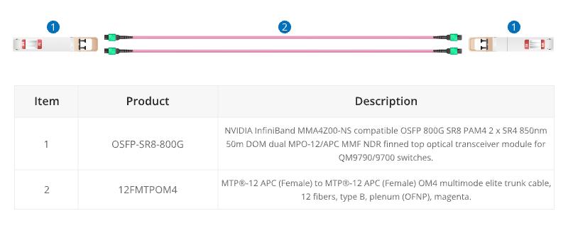
16 Fibers MTP® trunk cable is designed for 800G QSFP-DD/OSFP DR8 and 800G OSFP XDR8 optics direct connection and supporting 800G transmission for Hyperscale Data Center.

800G to 8X100G Interconnect

16 fibers MTP®-LC breakout cables are optimized for 800G OSFP XDR8 to 100G QSFP28 FR, 800G QSFP-DD/OSFP DR8 to 100G QSFP28 DR optics direct connection, and high-density data center applications.

800G to 2X400G Interconnect

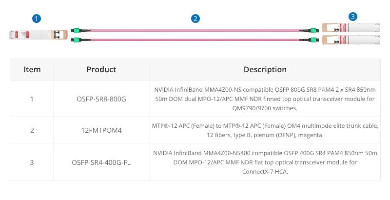
16 fiber MTP® conversion cable is designed to provide a more flexible multi-fiber cabling system based on MTP® products. Compared to purchasing and installing separate conversion cassettes, using MTP® conversion cables is a more cost-effective and lower-loss option. In the network upgrade from 400G to 800G, the ability to directly connect an 800G optical module and two 400G optical modules provides a more efficient use of cabling space, resulting in cost savings for cabling.

Conclusion

In a word, the choice of core number for MTP/MPO cables depends on the specific requirements of the network application. Matching the core number with the requirements of each scenario ensures optimal performance and efficient resource utilization. A well-informed choice ensures that your MTP/MPO cable not only meets but exceeds the demands of your evolving connectivity requirements.

How FS Can Help

As a global leader in enterprise-level ICT solutions, FS not only offers a variety of MTP/MPO cables but also customizes exclusive MTP/MPO cabling solutions based on your requirements, helping your data center network achieve a smooth upgrade. In the era of rapid growth in network data, the time has come to make a choice – FS escorts your data center upgrade. Register as an FS website member and enjoy free technical support.

A Guidance to Fiber Optic Cable Selection

With the advances of the information age, a great amount of people specialized in the field of network communication begins to attach great importance to the selection of fiber optic cables. From data and voice to security and videoconferencing, plenty of contemporary cable infrastructure services depend heavily on fiber optics to transmit information of farther distance at a higher speed, which makes fiber optics a standard component in daily communication nowadays. Fiber optics are considered to be a desirable cable medium because of its immunity to electromagnetic interference (EMI) and radio frequency interference (RFI) , not to mention its bandwidth that helps to meet the increased capacity demand, and its reliable reputation to ensure worry-free maintenance. This article is going to focus primarily on some essential component in fiber optic installation and provide some insight into selecting the right fiber optic cable.

The Necessities of Selecting the Right Type of Fiber

Fiber optic cable basically can be used in a wide variety of applications, ranging from small office LANs, data centers to inter-continental communication links. Moreover, its ability to transport signals for significant distances also contributes to its popularity in most networks, whether they are local, wide area or metropolitan. In fact, fiber optic cable is now running down many residential streets and brought directly to the house. Thus, choosing the appropriate fiber optic cable is extremely important for any installation.

It is known to all that the selection concerning the right type of fiber should be based on the immediate application since it varies in different circumstances. Besides, installers should also consider upcoming applications and capacity needs. Future bandwidth demands, transmission distances, applications, and network architecture influence fiber selection just as much as current needs. Therefore, a careful assessment of potential network usage will help avoid the costs of preventable upgrades.

Single-mode Fiber Optic Cable vs. Multimode Fiber Optic Cable

First and foremost, on selecting the right type of fiber, one should decide the mode of fiber needed. The mode of a fiber cable describes how light beams travel on the inside of the fiber cables themselves. Since the two modes aren’t compatible with each other and you can’t substitute one for the other, it is important to make the right choice.

Single-mode fiber optic cable uses a single strand of glass fiber for a single ray of light transmission, which can accommodate further distances and offer virtually unlimited bandwidth. Single-mode has the capacity to carry a signal for miles, making it an ideal option for telephone and cable television providers. And it is also usually employed in campus and metropolitan networks. Single-mode fiber requires laser technology for sending and receiving data, and the high-powered lasers transmit data at greater distances than the light used with multimode fiber.

Multimode fiber optic fiber, as the name indicates, allows the signal to travel in multiple modes, or pathways, along the inside of the glass strand or core. Multimode fiber optic cable is generally adopted in applications involving shorter distances like data center connections. Multimode fiber optic cable transmits Gigabit Ethernet up to 550 m, although it can’t compete with single-mode fiber optic cable in terms of transmission distance, multimode fiber cable is still proved to be a cost-efficient and economical solution.

Making the Connection

Connections play an essential role in keeping the information flowing from cable to cable or cable to device. There are lots of connector styles on the market including LC, FC, MT-RJ, ST and SC. There are also MPO/MTP style connectors that will accommodate up to 12 strands of fiber and take up far less space than other connectors. Among them, manufacturers and distributors are more likely to have equipment to accommodate ST and SC style connectors than any other connector style. Especially the SC connectors, with better performance against loss, more efficient installation and easier maintenance, has earned its place in today’s networking applications. As for those data center managers who attach more importance to space-saving, the LC connector is a more ideal option. These connectors offer even lower loss in a smaller form factor and provide higher performance and greater fiber density.

Evaluating Interface Options

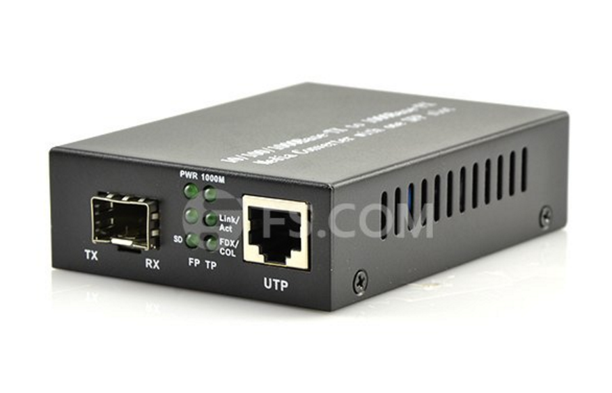
In addition to fiber type and connector selection, another vital issue for the technician is to evaluate the interface option which determines the network performance. The selection of interface is relevant to the fiber type, cable distance and speed of the connection as well. Installers can rely on modular Gigabit fiber-optic interfaces, called gigabit interface converters (GBICs) for most interface converters. These flexible interfaces come in several form factors, including XENPAK and SFP+, and can accommodate a variety of device applications. The picture below shows a typical gigabit fiber optic converter.

Gigabit fiber optic converter

While choosing the right interfaces, installers need to take their light sources into consideration. Light-emitting diodes (LEDs) work only with multimode fiber and operate at the 850nm window; laser works only with single-mode fiber and operates at the 1550nm window; and vertical-cavity surface-emitting laser (VCSEL) works with both types of fiber and operates at the 1310nm window.

Conclusion

In summary, to build a well-performed fiber optic system, realizing the applications and capacity expectations should be put into first place. As you can see, selecting the appropriate cable design for your application should require a thorough review of the entire pathway for the cable, including the type of fiber, optical connectors as well as interface options. The decision of selection can affect the fiber protection and performance, ease of the installation, splicing or termination, service lifetime, and, most importantly, cost.

Who is the Offender to Destroy the Fiber Cables?

Ever since fiber cables have been applied to the communication network, the fiber footprints cover all over the world. Fiber cables are essential components of nearly all modern computer and communications systems. They’re like the veins of the global communication systems, buried and aerial paths, even under the ocean. Fiber cables are all around us and incessantly supply the information and data to us. However, there is an annoying thing that once the fiber cables were damaged or cut, it may cause a big loss because of the network disruption. So, who is the offender to destroy fiber cables? This paper will tell you the truth, but unfortunately, there may be more than one.

Construction

Construction companies and excavators seem like the natural enemy of buried cables. Construction comes in many forms. Backhoes, post-hole augers and even hand shovels can all bring network traffic to a halt by severing your fiber optic cable. You would think that they would have called someone and tried to make sure they weren’t cutting into something dangerous like gas or oil. But ironically, they never do that before they dig.

1.construction

Nature & Weather

The biggest offender to destroy fiber cables are nature and extreme weather conditions. Hurricanes, mud slides, flood and ice storms etc. natural disaster and extreme weather are nightmare not only to our personal life and property, but also the fiber cables. We can make snowman and go skating in colder climates. What a pleasant thing! However, at this time, the frontline cable engineer must to do an emergency network repair under such harsh conditions in order to avoid additional damage and downtime. Because water that enters a splice enclosure can freeze, crushing the fiber strands and leaving you with a costly network outage. Additionally, lightning is also a factor to destroy fiber cables. When lightning strikes the ground, it will search for the best conductor available, even if it’s underground. If that happens to be the armor or trace-wire of your fiber cable, then damage to the cable sheath and even the fiber itself is very likely.

2.icesplicethumb

Artificial Destruction

Here humans refers to the people who steal the fiber. They cut the fiber thinking it has value and can be sold in pieces. The most classical event is that a 75 year-old woman in Georgia (country in Asia) was digging with her spade, looking for copper, which she wanted to sell for scrap, when she accidentally cut the fiber optic cable that provided internet to 90% of Armenia. It is ridiculous. It is fiber but not copper! In addition, people vandalize the fiber cable in other ways, e.g. for gun practice. This especailly happens in the rough parts of town which makes the cable repair work become dangerous. Furthermore, land disputes which causes artificial malicious damage of fiber is also a fiber damage reason.

3.human

Animals Chew & Bite

We can try to reason with humans and publicize our buried fiber cable, but there is nothing we can do about the cable damage causing by animals. Squirrel, a furry little nut eater, seems to be deeply fond of fiber cable sheathing besides nuts. We even doubt that the cable manufacturers of using peanut oil in the sheathing. Since they have a life-long drive to gnaw, squirrel is often responsible for extensive damage to fiber optic cable. Even metal armored cable can get cut in two by this furry critter. In addition, undersea cables aren’t exempt from cuts. Because there is another animal under ocean like to bite cables. It is shark. Why shark would like to eat fiber cables? Effect by magnetic fields is one of the explaining at present. We have no idea how we can combat these wayward rodents. Now, only thing we can do is always looking for ways to improve.

4animals-chew

Vehicle Damage

This is an unimaginable thing why vehicle will damage the fiber cable. Vehicle, here mainly refers to big trucks, or maybe small airplane. From people running into telephone poles to truckers underestimating the height of their rigs – it’s all part of the problem. For example, a cable damage accident causing by a truck happened in Pennsylvania. A trucker got lost and accidently turned down a residential street. His rig got tangled up in a mess of overhead phone cables. But that didn’t stop him! He kept pushing forward until his rig was tied up like a Christmas present. He was dragging a 20 foot section of broken telephone pole down the street before he stopped to see what was impeding his progress. To address this situation, we can forbid trucks from entering the residential street or city by limiting the height of the vehicles. However, accident always happens with all kinds of tricks, e.g. a small airplane will destroy the fiber cables. This happened in California. A small airplane was attempting to land at the Burbank International Airport and overshot the runway and crashed in a residential area. It clipped the poles that the aerial fiber was attached to, causing everything to come down. Though it is just a small probability event, it really refresh the record of fiber cut causing by vehicle.

5.Vehicle Damage

Cable Protection, Repair and Recovery

During all of these bizarre and annoying causes of fiber damage, no matter artificial destruction, natural disasters, animals, or even impossible odds, we may never know in advance which will happen, and even can’t blame it. Only thing we can do is to take a good protection for our fiber cables. Waterproof fiber cables, armored fiber cables and the other outdoor cables which are designed to protect fibers in a harsh application environment are widely used in this field. Of course, more better protection methods will be developed in the future. In fact, there are some force majeure factors which cause signal loss and cut the network. Repairs and recovery service are necessary. There is a group of people who are willing to get down into the trenches in the first time, make the necessary repairs and recovery service every time when network is down. They are great and worthy of respect.

6.repair&restore


Article From: Fiberstore Blog

Designing the Cabling System

The cable layout should be designed and a cable pulling plan developed, using the findings obtained during the site visit.The proposed cable layout should be drawn on to an existing cabling diagram of the site if it is not a new site installation. The cabling diagram that is used should include all existing cabling and cable housings. For example, all cable trays, conduits and pole lines should be illustrated. For the purpose of orientation, it is essential to incorporate outlines of buldings, roads, and fixed machinery in the diagram. The new fiber optic cable routes should then be drawn over the top of this with a dark pencil. Termination cabinets and fiber node points containg splicing trays and patch panels should also be drawn on to the diagram in pencil.

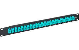
A typical building cable network layout is shown in Figure 1. In some countries, according to their loacal fire prevention codes, outdoor cables that are filled with jelly should be spliced to non-flammable indoor cables close to the cable entries. Alternatively, the fibers can be cleaned and enclosed in protective sleeving ‘zero cable’, and taken to the patch panel or optical fiber distribution frame (OFDF) directly. The cross-connection arrangements and distribution hardware needs to be specified for each cable.  In the market, there are type of fiber patch panel, for example, 12 port fiber patch panel, sc fiber patch panel, 16 port patch panel and so on. Our store offer you different types fiber optic patch panel to the customers, now we will introduce two hot sale types in our store.

black box patch panel

This Black box patch panel secures 12 breakout modules in the horizontal or zone distribution areas. It features a low profile that requires little wall space, as well as a large routing space for accessible patch cabling entrance. Top and bottom grommet holes provide easy entrance for the horizontal trunk cables. Incorporated spool rings can secure and store excess cable lengths with a safe bend radius.

24 fiber patch panel

With this High Density 24 port patch panel,  you can easily make one rack unit support your 10GB or higher applications. They allow you to quickly add new devices to your system without having to manually install or reconfigure other devices. The fiber is routed and connected on the inside of the cassette. There is no cutting, polishing, or terminating. These patch panels are perfect when you have high fiber count installations.

Figure 2 illustrates a typical cable layout diagram. Note that the diagram includes the cable fiber sizes (the number of strands in the fiber) to be installed, the locations for new and old pit boxes, the requirement for new conduit and for fiber optic termination cabinets.

If a fiber ring is being formed, the cables are normally cut in the pit, both ends are taken into the building where they are either spliced through or pig-tails are connected to the fibers before taken to a patch panel. Often, there is combination of spliced fibers (which are more secure compared to those on a patch panel) and fibers with pig-tails taken to a patch panel. Taking them to a patch panel allows the rings to be made or broken as required, but leaves them free to accidental removal. Compare the length of each cable run with the length of fiber optic cables on the reels that are to be used. Using this information, determine the location of any additional intermediate splicing locationg that are required.

Once the cable layout diagram is complete, a cable installation program should be drawn up. This document will be used by the contractor’s installation procedures and requirements. It should contain a thorough description of all the considerations and potential problems that were noted during the site survey.

The installation program should include a detailed description of the following information:

  • The logistics of pulling the cable.
  • Where the pulling equipment and cable reels should be located during the installation for each separate pull.
  • The precise location where the pit boxes, termination cabinets and splicing trays are to be located.
  • Which fibers are to be spliced and which fibers are to be taken through to a patch panel.
  • Each separate cable pull and the cable size and type to be pulled.
  • Each separate conduit installation and the size and type of conduit to be installed. Specify which conduit is to be used over each section.
  • Which cable trays are to be used.
  • The routes to be taken for cable runs through the roof space.
  • All the cable trays, conduits or other housings that will need replacing.
  • An installation schedule that would minimize traffic congestion while carrying out road works during peak hours.
  • The setting up of ‘no parking’areas where installation equipment is to be located. This should be carried out the day before the installation begins. This requirement should cover all pit boxes and manholes.
  • All observations that were made during the site visit.
  • The specific responsibilities of each member of the installation team should be defined.

When the installation is complete, document all the changes made during the installation and produce final‘as installed’drawings. This will help to ensure that the cables have been installed correctly and that future fault finding and any system upgrades will be hassle free.