A Guidance to Fiber Optic Cable Selection

With the advances of the information age, a great amount of people specialized in the field of network communication begins to attach great importance to the selection of fiber optic cables. From data and voice to security and videoconferencing, plenty of contemporary cable infrastructure services depend heavily on fiber optics to transmit information of farther distance at a higher speed, which makes fiber optics a standard component in daily communication nowadays. Fiber optics are considered to be a desirable cable medium because of its immunity to electromagnetic interference (EMI) and radio frequency interference (RFI) , not to mention its bandwidth that helps to meet the increased capacity demand, and its reliable reputation to ensure worry-free maintenance. This article is going to focus primarily on some essential component in fiber optic installation and provide some insight into selecting the right fiber optic cable.

The Necessities of Selecting the Right Type of Fiber

Fiber optic cable basically can be used in a wide variety of applications, ranging from small office LANs, data centers to inter-continental communication links. Moreover, its ability to transport signals for significant distances also contributes to its popularity in most networks, whether they are local, wide area or metropolitan. In fact, fiber optic cable is now running down many residential streets and brought directly to the house. Thus, choosing the appropriate fiber optic cable is extremely important for any installation.

It is known to all that the selection concerning the right type of fiber should be based on the immediate application since it varies in different circumstances. Besides, installers should also consider upcoming applications and capacity needs. Future bandwidth demands, transmission distances, applications, and network architecture influence fiber selection just as much as current needs. Therefore, a careful assessment of potential network usage will help avoid the costs of preventable upgrades.

Single-mode Fiber Optic Cable vs. Multimode Fiber Optic Cable

First and foremost, on selecting the right type of fiber, one should decide the mode of fiber needed. The mode of a fiber cable describes how light beams travel on the inside of the fiber cables themselves. Since the two modes aren’t compatible with each other and you can’t substitute one for the other, it is important to make the right choice.

Single-mode fiber optic cable uses a single strand of glass fiber for a single ray of light transmission, which can accommodate further distances and offer virtually unlimited bandwidth. Single-mode has the capacity to carry a signal for miles, making it an ideal option for telephone and cable television providers. And it is also usually employed in campus and metropolitan networks. Single-mode fiber requires laser technology for sending and receiving data, and the high-powered lasers transmit data at greater distances than the light used with multimode fiber.

Multimode fiber optic fiber, as the name indicates, allows the signal to travel in multiple modes, or pathways, along the inside of the glass strand or core. Multimode fiber optic cable is generally adopted in applications involving shorter distances like data center connections. Multimode fiber optic cable transmits Gigabit Ethernet up to 550 m, although it can’t compete with single-mode fiber optic cable in terms of transmission distance, multimode fiber cable is still proved to be a cost-efficient and economical solution.

Making the Connection

Connections play an essential role in keeping the information flowing from cable to cable or cable to device. There are lots of connector styles on the market including LC, FC, MT-RJ, ST and SC. There are also MPO/MTP style connectors that will accommodate up to 12 strands of fiber and take up far less space than other connectors. Among them, manufacturers and distributors are more likely to have equipment to accommodate ST and SC style connectors than any other connector style. Especially the SC connectors, with better performance against loss, more efficient installation and easier maintenance, has earned its place in today’s networking applications. As for those data center managers who attach more importance to space-saving, the LC connector is a more ideal option. These connectors offer even lower loss in a smaller form factor and provide higher performance and greater fiber density.

Evaluating Interface Options

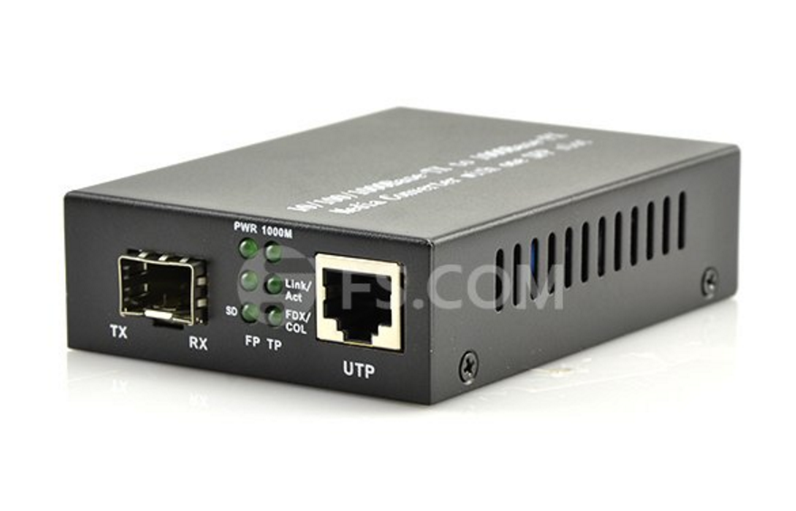
In addition to fiber type and connector selection, another vital issue for the technician is to evaluate the interface option which determines the network performance. The selection of interface is relevant to the fiber type, cable distance and speed of the connection as well. Installers can rely on modular Gigabit fiber-optic interfaces, called gigabit interface converters (GBICs) for most interface converters. These flexible interfaces come in several form factors, including XENPAK and SFP+, and can accommodate a variety of device applications. The picture below shows a typical gigabit fiber optic converter.

Gigabit fiber optic converter

While choosing the right interfaces, installers need to take their light sources into consideration. Light-emitting diodes (LEDs) work only with multimode fiber and operate at the 850nm window; laser works only with single-mode fiber and operates at the 1550nm window; and vertical-cavity surface-emitting laser (VCSEL) works with both types of fiber and operates at the 1310nm window.

Conclusion

In summary, to build a well-performed fiber optic system, realizing the applications and capacity expectations should be put into first place. As you can see, selecting the appropriate cable design for your application should require a thorough review of the entire pathway for the cable, including the type of fiber, optical connectors as well as interface options. The decision of selection can affect the fiber protection and performance, ease of the installation, splicing or termination, service lifetime, and, most importantly, cost.

Tips To Clean Fiber Optic Connectors

Fiber Optic Connectors are susceptible to be damaged which is not immediately obvious to the naked eye. The damage can have significant effects on measurements. Member any degradation of a fiber ferrule or fiber endface, any stray particles or finger oil on the endface, can have a significant effect on connector performance.

Fiber optic connector and connector ferrules have to be completely cleaned to make sure the trouble totally free working of fiber optic systems. As you’ve devote superior money installing a fiber optic, you might want to opt for a world course fiber optic connector cleaner and bnc coaxial connector to help keep it in superior shape.

Well, cleaning fiber optic connector can be done either with the help of a professional service provider or with the help of DIY kits. Below are a couple of time-tested methods.

1. Use Wipes And Solvents

This is probably the most widely used method of cleaning for the fiber optic parts. Cotton, cloth or lens paper is usually used for using this technique. Fabric and/or composite material wipes provide combined mechanical action and absorbency to remove contamination. Wipes should be used with a resilient pad in order avoid potential scratching of the connector end-face. Most solvents can provide good cleaning for the surfaces and tend to leave a slight residue that evaporates after a while.

This method is appropriate for cleaning connectors with exposed ferrules or termini but cannot be used to clean connector end-faces within alignment sleeves. The wipe should be constructed of material that is lint free and non-debris producing during the cleaning process. Please note that dry wipes have been shown to leave a static charge on the end-face of the connector which can thereafter attract particulate contamination. Therefore it is recommended that a static dissipative solvent be used with a dry wipe to eliminate this condition.

If the connector is not clean after the first cleaning, the process can be repeated perhaps with slightly more pressure on the connector to increase the mechanical action and perhaps making several stokes from the damp to dry sections of the cleaning material.

2. Cleaning Through Connector Reels

Optipop and Cletop are the most widely used reel connectors that are used in the industry for proper cleaning solutions. These work on the function of a resilient pad, sliding dust cover as well as a certain mechanism that tends to keep these small parts of the gadget working known as the ratcheting mechanism. The connector is inserted into an Fiber Optic Inspection scopes. This is done to check how clean the connector is.

About Solvents

Solvents used to clean fiber optics should be static-dissipative and residue-free. Many solvents are flammable and/or packaged so that transportation of the solvent is considered a hazardous material increasing cost of shipment and storage of the solvent. However, there are solvents available that are non-flammable and non-hazardous and packaged so that shipping requires no additional fees or paperwork.

Mind:

The methods require technical skill and expertize, it is advisable to trust the best in line professionals for fiber optic cleaning. Professional groups will not only ensure that your connectors are taken good care of, but also will prevent any sort of technical failures due to improper cleaning techniques.

A comprehensive understanding of fiber optic connectors

Fiber connector has traditionally been the biggest concern in using fiber optic systems. While connectors were once unwiedy and difficult to use, connector manufacturers have standardized and simplified connectors greatly. This increases the user use convenient increase in the use of optical fiber systems; It is also emphasising taken proper care of and deal with the optical connector. This article covers connector basics including the parts of a fiber optic connector, installing fiber optic connectors, and the cleaning and handling of installed connectors. For information on connector loss, see Connector Loss Test Measurement.

Optical fiber to fiber optic interconnection can be made by a joint, a permanent connection, or a connector, and is different from the plug in it can be to disconnect and reconnect. Fiber optic connector types are as various as the applications for which they were developed. Different connector types have different characteristics, different advantages and disadvantages, and different performance parameters. But all connectors have the same four basic components.

The Ferrule

The fiber is installed in a long, thin cylinder, the ferrule, which act as a fiber alignment mechanism. The ferrule is bored through the center at a diameter that is slightly larger than the diameter of the fiber cladding. The end of the fiber is located at the end of the ferrule. Ferrules are typically made of metal or ceramic, but they may also be constructed of plastic.

The Connector Body

Also known as the connector housing, the body holds the ferrule. It is usually constructed of metal or plastic and includes one or more assembled pieces which hold the fiber in place. The details of these connector body assemblies vary among connectors, but the welding and/or crimping is commonly used to attach strength members and cable jackets to the connector body. The ferrule extends past the connector body to slip into the couping device.

The Cable

The cable is attached to the connector body. It acts as the point of entry for the fiber. Often, a strain relief boot is added over the junctioni between the cable and the connector body, providing extra stength to the junction.

The Coupling Device

Most fiber optic connectors do not use the male-female configuration common to electronic connectors. Instead, a coupling device such as an alignment sleeve is used to mate the connectors. Similar devices may be installed in fiber optic transmitters and receivers to allow these devices to be mated via a connector. These devices are also known as feed-through bulkhead adapters.

Table 1 illustrates some types of optical connectors and lists some specifications. Each connector type has strong points.

Table 1- Types Of Optical Connectors

Installing Fiber Optic Connectors

The method for attaching fiber optic connectors to optical fibers varies among connector types. While not intended to be a definitive guide, the following steps are given as a reference for the basic of optical fiber interconnection.

Cut the cable one inch longer than the required finished length.

Carefully strip the outer jacket of the fiber with “no nick” fiber strippers. Cut the exposed strength members, and remove the fiber coating. The fiber coating can be removed in two ways: a. by soaking the fiber for two minutes in paint thinner and wiping the fiber clean with a soft, lint-free cloth; b. by carefully stripping the fiber with afiber stripper. Be sure to use strippers made specifically for use strippers made specifically for use with fiber rather than metal wire strippers as damage can occur, weakening the fiber.

Thoroughly clean the bared fiber with isopropyl alcohol poured onto a soft, lint-free cloth such as kimwipes. NEVER clean the fiber with a dry tissue.

Note: Use only industrial grade 99% pure isopropyl alcohol. Commercially available medicinal and isopropyl alcohol is light mineral oil dilution water. Industrial grade isopropyl alcohol should be dedicated.

The connector may be connected by applying epoxy or by crimping. If using expoxy, fill the connector with enough epoxy to allow a small bead of epoxy to form at the tip of the connector. Insert the clean, stripped fiber into the connector. Cure the epoxy according to the instructions provided by the epoxy manufacturer.
Anchor the cable strength members to the connector body. This prevents direct stress on the fiber. Slide the back end of the connector into place (where applicable).

Prepare fiber face to achieve a good optical finish by cleaving and polishing the fiber end. Before the connection is made, the end of each fiber must have a smooth finish that is free of defects such as hackles, lips, and fractures. These defects, as well as other impurities and dirt change geometry transmission patterns of light and scattered.

Cleaving

Cleaving involves cutting the fiber end flush with the end of the ferrule. Cleaving, also called the scrible-and-break method of fiber end face preparation, takes some skill to achieve optimum results. Properly handled, the cleave produces a perpendicular, mirror-like finish. Incorrect cracks will cause the lips and the comb as shown in Figure 2. While cleaving may be done by hand, a cleaver tool, available from such manufacturers as Fujikura and FiberStore, allows for a more consistent finish and reduces the overall skill required.

The steps listed below outline one procedure for producing good, consistent cleaves such as the one shown in Figure 3. 1. Place the blade of the cleaver tool at the tip of the ferrule. 2. Gently score the fiber across the cladding region in one direction. If the scoring is not done lightly, the fiber may break, making it necessary to reterminate the fiber. 3. Pull the excess, cleaved fiber up and away from the ferrule. 4. Carefully dress the nub of the fiber with a piece of 12-micron alumina-oxide paper. 5. Do the final polishing. (See Figure 3.)

Polishing

After clean cleave has been achieved, the fiber end face is attached to a polishing brush, and the fiber is ground and polished. The proper finish is achieved by rubbing the computerized fiber end against polishing paper in a figure-eight pattern approximately sixty times.

To increase the ease and repeatability of connector installation, some companies provide the connector kits. Some kits are specific to the type of connector to be installed while others supply the user with general tools and informationi for connecting different types of connectors. Some connectors require the use of an alignment sleeve, also called an interconnection sleeve. This sleeve serves to increase repeatability from connection to connection.

Care and Handling of Fiber Optic Connectors

A number of events can damage fiber optic connectors. Unprotected connector ends can experience damage by impact, airborne dust particles, or excess humidity or moisture. Increase the optical output power of modern lasers may damage a connector, an often overlooked factor in discussions about handling and caring for optical fibers and connectors. Most designers tend to think of the power levels in optical fibers as relatively insignificant. However, a few milliatts at 850nm will do permanent damage to a retina. Today, optical amplifiers can generate optical powers of 1 watt of more into a single-mode fiber. This becomes quite significant when one considers that the optical power is confined in the optical core only a few microns in diameter. Power densities in a single-mode fiber carrying an optical power of 1 Watt (+30 dBm) can reach 3 megawatts/cm2 or 30 gigawatts/m2! To put it in everyday terms, sunlight at the surface of the Earth has a power density of about 1,000 Watts/m2. Most organic materials will combust when exposed to radiant energies of 100 kilowatts/m2. Clearly, power densities of 30 gigawatts/m2 deserve attention.

Cleaning

Another important thing to remember in handling fiber optic connector is that the fiber end face and ferrule must be absolutely clean before it is inserted into a transmitter or receiver. Dust, lint, oil (from touching the fiber end face), or other foreign particles obscure the end face, compromising the integrity of the optical signal being sent over the fiber. From the optical signal’s point-of-view, dirty connections are like dirty windows. Less light gets through a dirty window than a clean one. It is hard to conceive of the size of a fiber optic connector core. Single-mode fibers have cores that are only 8-9 µm in diameter. As a point of reference, a typical human hair is 50-75 µm in diameter, approximately 6-9 times larger! Fiber optic connectors need to be cleaned every time they are mated and unmated; it is essential that fiber optics users develop the necessary discipline to always clean the connectors before they are mated. It is also important to cover a fiber optic connector when it is not in use.

Handling

Never touch the fiber end face of the connector.
Connectors not in use should be covered over the ferrule by a plastic dust cap. it is important to note that inside of the ferrule dust caps contain a sticky residue that is a by product of making the dust cap. This residue will remain on the ferrule end after the cap is removed.

The use of index-matching gel, a gelatinous substance that has a refractive index close to that of the optical fiber, is a point of contention between connector manufacturers. Glycerin, available in any drug store, is a low-cost, effective index-matching gel. Using glycerin will reduce connector loss and back reflection, often dramatically. However, the index-matching gel may collect dust or abrasives that can damage the fiber end faces. It may also leak out over time, causing backreflections to increase.