In the era of ultra-high-speed data transmission, MTP/MPO cables have become a key player, especially in the context of 800G networks. In essence, MTP/MPO cables emerge as catalysts for the evolution toward 800G networks, offering a harmonious blend of high-density connectivity, reliability, and scalability. This article will delve into the advantages of MTP/MPO cables in 800G networks and provide specific solutions for constructing an 800G network, offering valuable insights for upgrading your existing data center.
Challenges Faced in 800G Data Transmission
As a critical hub for storing and processing vast amounts of data, data centers require high-speed and stable networks to support data transmission and processing. The 800G network achieves a data transfer rate of 800 Gigabits per second (Gbps) and can meet the demands of large-scale data transmission and processing in data centers, enhancing overall efficiency.
Therefore, many major internet companies are either constructing new 800G data centers or upgrading existing data centers from 100G, 400G to 800G speeds. However, the pursuit of 800G data transmission faces numerous complex challenges that necessitate innovative solutions. Here, we analyze the intricate obstacles associated with achieving ultra-fast data transmission.
Insufficient Bandwidth & High Latency
The 800G network demands extensive data transmission, placing higher requirements on bandwidth. It necessitates network equipment capable of supporting greater data throughput, particularly in terms of connection cables. Ordinary optical fibers typically consist of a single fiber within a cable, and their optical and physical characteristics are inadequate for handling massive data, failing to meet the high-bandwidth requirements of 800G.
While emphasizing high bandwidth, data center networks also require low latency to meet end-user experience standards. In high-speed networks, ordinary optical fibers undergo more refraction and scattering, resulting in additional time delays during signal transmission.
Limited Spatial Layout
The high bandwidth requirements of 800G networks typically come with more connection ports and optical fibers. However, the limited space in data centers or server rooms poses a challenge. Achieving high-density connections requires accommodating more connection devices in the constrained space, leading to crowded layouts and increased challenges in space management and design.
Complex Network Architecture
The transition to an 800G network necessitates a reassessment of network architecture. Upgrading to higher data rates requires consideration of network design, scalability, and compatibility with existing infrastructure. Therefore, the cabling system must meet both current usage requirements and align with future development trends. Given the long usage lifecycle of cabling systems, addressing how to match the cabling installation with multiple IT equipment update cycles becomes a challenging problem.
High Construction Cost
Implementing 800G data transmission involves investments in infrastructure and equipment. Achieving higher data rates requires upgrading and replacing existing network equipment and cabling management patterns, incurring significant costs. Cables, in particular, carry various network devices, and their required lifecycle is longer than that of network equipment. Frequent replacements can result in resource wastage.
Effectively addressing these challenges is crucial to unlocking the full potential of a super-fast, efficient data network.

Unlocking 800G Power: MTP/MPO Cables’ Key Advantages
The significance of MTP/MPO cables in high-speed networks, especially in 800G networks, lies in their ability to manage the escalating data traffic efficiently. The following are key advantages of MTP/MPO cables:
High Density, High Bandwidth
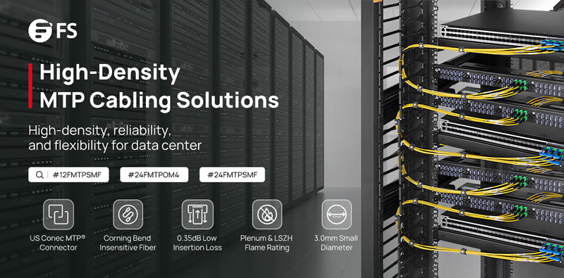
MTP/MPO cables adopt a high-density multi-fiber design, enabling the transmission of multiple fibers within a relatively small connector. This design not only provides ample bandwidth support for data centers, meeting the high bandwidth requirements of an 800G network, but also helps save space and supports the high-density connection needs for large-scale data transfers.
Additionally, MTP/MPO cables exhibit excellent optical and mechanical performance, resulting in low insertion loss in high-speed network environments. By utilizing a low-loss cabling solution, they effectively contribute to reducing latency in the network.
Flexibility and Scalability
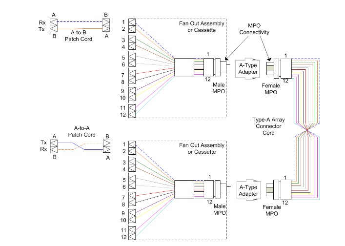
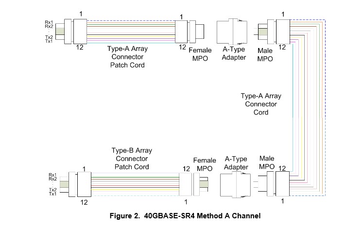
MTP/MPO connectors come in various configurations, accommodating different fiber counts (8-core, 12-core, 16-core, 24-core, etc.), supporting both multimode and single-mode fibers. With trunk and breakout designs, support for different polarities, and male/female connector options, these features allow seamless integration into various network architectures. The flexibility and scalability of MTP/MPO connectors enable them to adapt to evolving network requirements and facilitate future expansions, particularly in the context of 800G networks.
Efficient Maintenance
The high-density and compact design of MTP/MPO cables contribute to saving rack and data room space, enabling data centers to utilize limited space resources more efficiently. This, in turn, facilitates the straightforward deployment and reliable operation of 800G networks, reducing the risks associated with infrastructure changes or additions in terms of cost and performance. Additionally, MTP/MPO cables featuring a Plenum (OFNP) outer sheath exhibit fire resistance and low smoke characteristics, minimizing potential damage and saving on cabling costs.
Scaling the 800G Networks With MTP/MPO Cables
In the implementation of 800G data transmission, the wiring solution is crucial. MTP/MPO cables, as a key component, provide reliable support for high-speed data transmission. FS provides professional solutions for large-scale data center users who require a comprehensive upgrade to 800G speeds. Aim to rapidly increase data center network bandwidth to meet the growing demands of business.
Newly Built 800G Data Center
Given the rapid expansion of business, many large-scale internet companies choose to build new 800G data centers to enhance their network bandwidth. In these data centers, all network equipment utilizes 800G switches, combined with MTP/MPO cables to achieve a direct-connected 800G network. To ensure high-speed data transmission, advanced 800G 2xFR4/2xLR4 modules are employed between the core switches and backbone switches, and 800G DR8 modules seamlessly interconnect leaf switches with TOR switches.
To simplify connections, a strategic deployment of the 16-core MTP/MPO OS2 trunk cables directly connects to 800G optical modules. This strategic approach maximally conserves fiber resources, optimizes wiring space, and facilitates cable management, providing a more efficient and cost-effective cabling solution for the infrastructure of 800G networks.

Upgrade from 100G to 800G
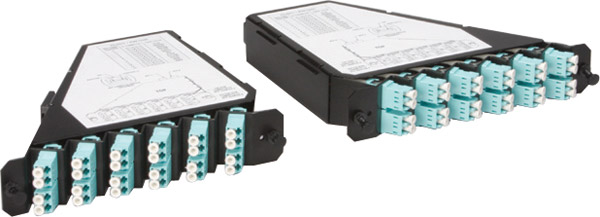
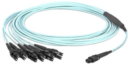
Certainly, many businesses choose to renovate and upgrade their existing data center networks. In the scenario below, engineers replaced the original 8-core MTP/MPO-LC breakout cable with the 16-core version, connecting it to the existing MTP cassettes. The modules on both ends, previously 100G QSFP28 FR, were upgraded to 800G OSFP XDR8. This seamless deployment migrated the existing structured cabling to an 800G rate. It is primarily due to the 16-core MTP/MPO-LC breakout cable, proven as the optimal choice for direct connections from 800G OSFP XDR8 to 100G QSFP28 FR or from 800G QSFP-DD/OSFP DR8 to 100G QSFP28 DR.
In short, this solution aims to increase the density of fiber optic connections in the data center and optimize cabling space. Not only improves current network performance but also takes into account future network expansion.

Elevating from 400G to the 800G Network
How to upgrade an existing 400G network to 800G in data centres? Let’s explore the best practices through MTP/MPO cables to achieve this goal.
Based on the original 400G network, the core, backbone, and leaf switches have all been upgraded to an 800G rate, while the TOR (Top of Rack) remains at a 400G rate. The core and backbone switches utilise 800G 2xFR4/2xLR4 modules, the leaf switches use 800G DR8 modules, and the TOR adopts 400G DR4 modules. Deploying two 12-core MTP/MPO OS2 trunk cables in a breakout configuration between the 400G and 800G optical modules facilitates interconnection.

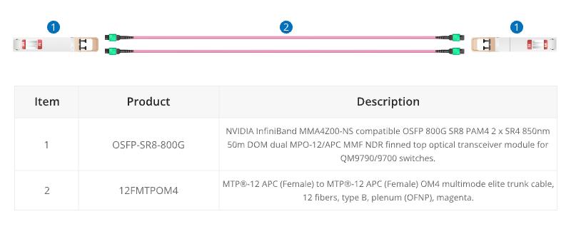
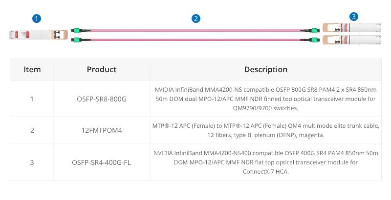
Furthermore, there is a second connectivity option where the 800G port optical module utilises OSFP SR8, the 400G port uses OSFP SR4 optical module, and the intermediate cables are connected using 12-core MTP® OM4 trunk cables.

These two cabling solutions enhance scalability, prevent network bottlenecks, reduce latency, and are conducive to expanding bandwidth when transitioning from lower-speed to higher-speed networks in the future. Additionally, this deployment retains the existing network equipment, significantly lowering cost expenditures.
| Item | Product | Description |
|---|---|---|
| 1 | OSFP-DR8-800G | NVIDIA InfiniBand MMS4X00-NM compatible OSFP 800G DR8 PAM4 2x DR4 1310nm 500m DOM dual MPO-12/APC NDR SMF optical transceiver, finned top. |
| 2 | OSFP800-XDR8-B1 | Generic compatible 800GBASE-XDR8 OSFP PAM4 1310nm 2km DOM MTP/MPO-16 SMF optical transceiver module. |
| 3 | OSFP-2FR4-800G | NVIDIA InfiniBand MMS4X50-NM compatible OSFP 800G 2FR4 PAM4 1310nm 2km DOM dual LC duplex/UPC NDR SMF optical transceiver, finned top. |
| 4 | OSFP-SR8-800G | NVIDIA InfiniBand MMA4Z00-NS compatible OSFP 800G SR8 PAM4 2 x SR4 850nm 50m DOM dual MPO-12/APC MMF NDR finned top optical transceiver module for QM9790/9700 switches. |
| 5 | OSFP-SR4-400G-FL | NVIDIA InfiniBand MMA4Z00-NS400 compatible OSFP 400G SR4 PAM4 850nm 50m DOM MPO-12/APC MMF NDR flat top optical transceiver module for ConnectX-7 HCA. |
| 6 | 16FMTPSMF | MTP®-16 APC (Female) to MTP®-16 APC (Female) OS2 single mode standard IL trunk cable, 16 fibers, plenum (OFNP), yellow, for 800G network connection. |
| 7 | 16FMTPLCSMF | MTP®-16 APC (Female) to 8 LC UPC duplex OS2 single mode standard IL breakout cable, 16 Fibers, plenum (OFNP), yellow, for 800G network connection. |
| 8 | 12FMTPSMF | MTP®-12 (Female) to MTP®-12 (Female) OS2 single mode elite trunk cable, 12 fibers, type B, plenum (OFNP), yellow. |
| 9 | 12FMTPOM4 | MTP®-12 APC (Female) to MTP®-12 APC (Female) OM4 multimode elite trunk cable, 12 fibers, type B, plenum (OFNP), magenta. |
For more specific 800G connectivity solutions, please refer to 800G MTP/MPO Cabling Guide.
Conclusion
Ultimately, the diverse range of MTP/MPO cable types provides tailored solutions for different connectivity scenarios in 800G networks. As organizations navigate the complexities of high-speed data transmission, MTP/MPO cables stand as indispensable enablers, paving the way for a new era of efficient and robust network infrastructures.
How FS Can Help
The comprehensive networking solutions and product offerings not only save costs but also reduce power consumption, delivering higher value. Considering an upgrade to 800G for your data center network? FS tailors customized solutions for you. Don’t wait any longer—Register as an FS website member now and enjoy free technical support.


