24-Fiber Trunk Cabling Solution for 40 Gigabit Ethernet

Year by year, the amount of data transmitted at data centers is skyrocketing as networks need to support more devices and advanced applications than ever before. Typical transmission speeds in the data center are also increasing from 10Gbps to 40Gbps, to 100Gbps or beyond, and in 2010, the IEEE ratified the 40 and 100 gigabit Ethernet (GbE) standard.

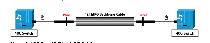
Data centers, at the heart of tremendous amount of data to be transmitted, need fiber optic links greatly to provide high bandwidth and low latency for data operation. The 24-fiber trunk cables, one type of fiber optic links, are able to deliver higher data transmission speed and bandwidth, better performance and more efficient scalability. 24-fiber trunk cables are considered as the suitable solution for 40GbE transmission. This text mainly introduces one 40GbE cabling solution: 24-fiber trunk cables.

What Does the 40GbE Standard Define?

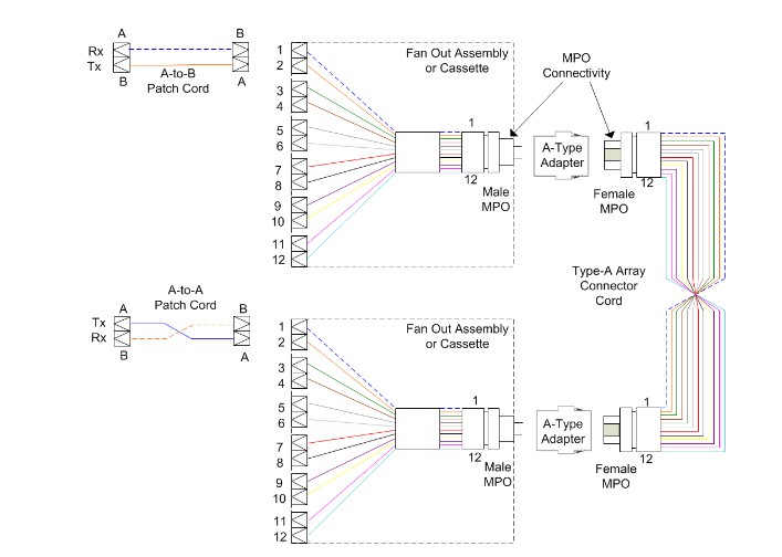
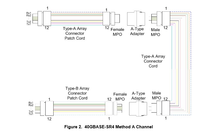
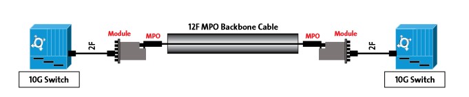
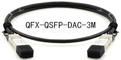
The efforts aimed to support speeds of 40Gbps led to the ratification of the 802.3ba standard. This standard for 40Gbps uses parallel optics, or multiple lanes of fiber transmitting at the same speed. Most 40GbE infrastructure uses a 12-fiber MPO connector, requiring 8 fibers, with each 4 fibers transmitting at 10Gbps and the other 4 fibers receiving at 10Gbps, while the inner 4 optical fibers are left unused. According to IEEE 802.3ba standard, multi-mode fiber (MMF) supports 40GbE with link lengths up to 100m over OM3 optical fiber and up to 150m over OM4. Single-mode fiber (SMF)supports 40GbE with link lengths up to 40km when applied for longer distance transmission. Besides, copper cable is is also capable of supporting 40GbE when very short distance is required, such as EX-QSFP-40GE-DAC-50CM and QFX-QSFP-DAC-3M. Take QFX-QSFP-DAC-3M for example, Fiberstore compatible Juniper QFX-QSFP-DAC-3M establishes 40GbE with the link lengths of 3m.

QFX-QSFP-DAC-3M establishes 40GbE with the link lengths of 3m

Here introduces a better standards-based 40GbE cabling solution with 24-fiber trunk cables.

The use of 24-fiber trunk cables between switch panels and equipment is a wise solution. In this approach, 24-fiber trunk cables with 24-fiber MPOs on both ends are used to connect from the back of the switch panel to the equipment distribution area. This solution is appropriate for 40GbE owing to its following advantages.

Reduced Cable Congestion

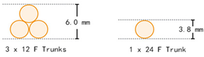
Another advantage of using 24-fiber trunk cables comes to the reduced cable congestion. Data centers’ priority is the space in infrastructure, since congested cables would make cable management more difficult. 24-fiber trunk cables are only appreciably larger than 12-fiber trunk cables at 3.8 mm in diameter, compared to 3 mm. That means the 24-fiber trunk cables provide twice the amount of fiber in less than 21% space. For a 40GbE application, it takes three 12-fiber trunk cables to provide the same number of links as a single 24-fiber trunk cable.

24-fiber trunk  cableS reduce cable congestion

Maximum Fiber Utilization

As mentioned previously, 40GbE uses eight fibers of a 12-fiber MPO connector, the remaining four fibers unused. When using a 12-fiber trunk cable, those same four fibers are also unused. But with the use of 24-fiber trunk cables, all the fibers are actually used. The use of all the 24-fiber trunk cables create three 40GbE links. This recoups 33% of the fibers that would be lost with 12-fiber trunk cables, providing a much better return on investment.

Conclusion

24-fiber trunk cabling solution delivers high bandwidth to data-hungry applications along with low end to end latency, enabling data centers to operate with high performance and efficiency. Fiberstore supplies a large number of 24-fiber trunk cables, and other cables for 40G solution, including EX-QSFP-40GE-DAC-50CM and QFX-QSFP-DAC-3M mentioned above. Besides, Fiberstore also offers other 40G solution products, like 40G QSFP+ transceivers which are fully compatible with major brand, such as Cisco, HP and Dell (eg. Dell QSFP+), You can visit Fiberstore for more information about 40G solution.

The use of The MPO In 10GBASE-SR and 40GBASE-SR chanels

Purpose

The purpose of this document is to describe the usage and reason behind the development and characteristics of the MPO to be utilized in 10GASE-SR and 40GBASE-SR4 channels.

Background

MPO connectivity has become widely used throughout the industry not only to reduce cable density but also to prepare for the migration from 10GBASE-SR to 40GBASE-SR.

With the 10GBASE-SR transmission, there are two fibers associated with the channel one fiber for transmit and one fiber for receive. This configuration is often referred to as a duplex channel. The polarity of these channels (TX to RX) is relatively easy to manage from end to end and if polarity correction is required, it is easy to accomplish in the field by rearranging the fibers in the duplexing clip. Also, when two of these connectors need to be mated, an adapter with a split sleeve is used to align the ferrules of the two connectors. Shown below is a typical 10GBASE-SR Method A channel.

10GBASE - SR Method A Channel

In an existing 10G Ethernet fiber infrastructure, LC to MPO cassettes are replaced with MPO adapter panels, and LC to LC patch cords are replaced with MPO patch cords during migration to 40G Ethernet. In this example, three different types of patch cords are required for the migration: Method A/Female to Male, Method A/Male to Male, and Method B/Female to Male. Using patch cords terminated with MPO Connectors, only one type of patch cord needs to be purchased and stocked and can be configured on the fly to replace any of the three needed patch cords.

In the 40GBASE-SR transmission, there are eight fibers associated with the channel four fibers for the TX signal and four fibers for the RX signal. With multiple fibers being utilized, the polarity of the channel becomes harder to manage from end to end. Additionally, mating of two MPO connectors is not completed with an adapter with a split sleeve but rather with alignment pins that are a fixture on the MPO connector. One MPO connects or has alignment holes (this connector is referred to as a female MPO) and the other MPO connector has alignment pins. (this connector is referred to as a male MPO).

These two connectors are mated together in a genderless MPO adapter. Figure 2 shows a typical 40GBASE-SR Method A channel.

40GBASE-SR4 Method A Channel

When using MPO-based connectivity in the 10G channel, the standard, ANSI/TIA-568C.1-7, calls for a female MPO horizontal cabling infrastructure (as shown in Figure 1) and a male MPO cassette. The male MPO is located within the cassette to protect the fragile alignment pins from damage during installation. In a 40G channel configuration, cassettes are not used and therefore cannot serve to protect the pins. Consequently, in the 40G channel configuration the standard calls for male MPO horizontal cabling (as shown in Figure 2) to protect the alignment pins on the back side of the adapter module rather than have them exposed to possible damage on the end of a patch cord. Male connectors on patch cords pose an additional operational risk to QSFP+ ports should a male connector be inserted due to the QSFP+ ports being configured as male to protect the pins within the port. The following are the products about 40G QSFP+ MTP MPO to QSFP+ Assembly from FS.

MTP trunk cable

QSFP+ MTP/MPO fiber trunk cable assemblies are interconnecting QSFP+ transceivers operating within 40GBASE-SR parallel optics networks. QSFP+ transceivers utilize 12Fibres MPO/MTP interface and perform 40G transmission using 4 x 10G channels (8 fibres: 4 x TX and 4 x RX ). FS MTP/MPO QSFP+ assemblies are built with the highest quality components. MTP/MPO as well low loss Elite versions are offered featuring low insertion loss for demanding high-speed networks where power budgets are critical.

Considering this discussion, to comply with the ANSI/TIA-568C.1-7 cabling guidelines and provide optimal pin protection when migrating from a 10G to 40G cabling configuration, the MPO connectors associated with the horizontal cabling infrastructure must be changed from female to male. Given that existing MPO connectivity does not allow for this alteration in the field without significant risk of fiber or connector damage, it seems that the cabling in the horizontal cabling infrastructure would need to be changed out.

In the Method A configuration shown in Figure 2, there are also two different MPO patch cords necessary to complete the 40G channel. Not only does the horizontal cabling MPO change from female to male, but a Method A cord and Method B cord are needed at the ends to complete the channel to ensure proper polarity.

A Method B configuration holds the same gender issues as Method A when migrating from 10G to 40G, but does not need the two different MPO patch cords to complete the channel.

Testing is another challenge present with MPO horizontal solutions. Some testers have a fixed male MPO interface while others have a fixed female MPO interface. In both cases, the preferred jumper testing method, Method B, per TIA-568-C (TIA-526-14A and TIA-526-7) cannot be used for both the male horizontal and female horizontal cabling infrastructures. In the case where the MPO interface on the tester does not match the MPO in the horizontal infrastructure, a three-jumper method would need to be utilized. The three-jumper method introduces more variability and the possibility for error in the testing.

For example, Figure 3 shows a tester with fixed Male MPO interfaces on the source and meter units. When setting the reference, you will need to use a female-to-female MPO reference cord. After setting the reference, to test a female horizontal cabling infrastructure, a third reference cable with a male end would need to be introduced to properly test the horizontal cabling infrastructure.

In any of these cases changing either the polarity or gender of the standard MPO connector in the field is not recommended due to the complex construction of the connector. Trying to change either of these characteristics in the field is extremely difficult and may lead to damage to the fiber exposed when attempting to replace the connector housing.

MTP MPO Fiber Cable is offered for various applications for all networking and device needs like 100G/40G modules. It uses a high-density multi-fiber connector system built around precision-molded MT ferrule. FS MPO fiber cables are available in UPC and APC finishes, support both multimode and single-mode applications, and have optional lengths available. Our MTP/MPO fiber cable is with push connector IEC 61754-7 and TIA/EIA 604-5A compliant and offers low cost per termination for high-density applications. The MPO/MTP fiber cables are tested with guaranteed quality, and they can be installed easily, which saves time and money.

40/100G With OM3 and OM4 In MPO Cabling Data Center

With the continued requirement for expansion and scalability in the data center, cabling infrastructures must provide reliability, manageability, and flexibility. Deployment of an optical connectivity solution allows for an infrastructure that meets these requirements for current and future data rates. A key factor when choosing the type of optical connectivity is scalability. Scalability refers to not only the physical expansion of the data center concerning additional servers, switches, or storage devices but also to the scalability of the infrastructure to support a migration path for increasing data rates. As technology evolves and standards are completed to define data rates such as 40G and 100G Ethernet, 32G and higher-speed Fibre Channel, and 40G and higher-speed InfiniBand, the cabling infrastructures installed today must provide scalability to accommodate the need for more bandwidth in support of future applications.

As Data Center bandwidth requirements increase due to requirements for additional switching and routing, virtualization, convergence, video-on-demand (VoD), and high-performance cloud computing, the need for reliable and high-performance cabling infrastructure to support these applications becomes more important. The IEEE 802.3ba 40G/100G Ethernet standard guides 40G/100G transmission with multimode and singlemode fiber. OM3 and OM4 are the only multimode fibers included in the standard.

In addition to the cable performance, the choice of physical connection interface is also important. Since parallel-optics technology requires data transmission across multiple fibers simultaneously, a multifiber connector is required. Factory terminated MPO MTP connectors which have either 12 fiber or 24 fiber array, will support this solution. For example, a 10G system would utilize a single MPO/MTP (12 Fiber) connector between the 2 switches. Modules are placed on the end of the MPO connector to transition from an MPO connector to a 12 Fiber breakout LC duplex or SC duplex cable assembly. This enables connectivity to the switch. 40G and 100G systems require a slightly different configuration. Individual modules and subracks as well as various cable assemblies are available which provide an MPO/MTP interface and which also provide connectivity to LC, and SC connectors.

Factory-terminated MPO solutions allow connectivity to be achieved through a simple plug-and-play system. To meet the needs of today’s serial Ethernet applications, MPO-terminated backbone/horizontal cabling is simply installed into pre-terminated modules, panels, or harnesses (Figure 1).

Fiber MPO Cable

Cabling migration from 10G to 40G to 100G in an MPO-based system is a simple and easy deployment. Starting with 10G, a 12 fiber cable is deployed between the two 10G switches. Modules are used at the end to transition from the 12-fiber MPO to the LC duplex. This enables connectivity into the switch (Figure 2).

12 Fiber

When the switches migrate to 40G, the module is removed and replaced by a 12-fiber MPO adapter panel. The use of a 12-fiber MPO jumper is needed to establish connectivity between the switches (Figure 3).

MPO Fiber

Insertion loss is a critical performance parameter in current data center cabling deployments. Total connector loss within a system channel impacts the ability of a system to operate over the maximum supportable distance for a given data rate. The 40G and 100G Ethernet standard specifies the OM3 fiber 100-meter distance maximum channel loss to be 1.9 dB, which includes a 1.5-dB total connector loss. The OM4 fiber 150-meter distance maximum channel loss is 1.5 dB, which includes a 1.0-dB total connector loss budget. The insertion loss specifications of the MPO connectivity components should be evaluated when designing data center cabling infrastructures. With low-loss MPO connectivity components, maximum flexibility can be achieved with the ability to introduce multiple connector matings into the connectivity link such that structured cabling architectures can be supported.

Cabling deployed in the data center today must be selected to support data rate applications of the future, such as 100G Ethernet, Fibre Channel ≥32G, and InfiniBand ≥40G. To do this, OM3 or OM4 fiber is a must. In addition to being the only multimode fibers included in the 40G and 100G Ethernet standards, OM3 and OM4 fibers provide the highest performance as well as the extended reach often required for structured cabling installations in the data center.

Multiple loss-performance tiers are available for MPO connectivity solutions. Just as connector loss must be considered with current, deployed applications such as 10G Ethernet, insertion loss is also a critical factor for 40G and 100G Ethernet applications. For example, IEEE 802.3ae defines a maximum distance of 300 meters on OM3 multimode fiber for 10G Ethernet (10GBase-SR). To achieve this distance, a total link loss of 2.6 dB is needed with a maximum total connector loss of 1.5 dB. As the total connector loss in the channel increases above 1.5 dB, the supportable distance decreases the channel loss increases. When extended distances or multiple connector matings are required, low-loss performance modules and connectivity may be necessary. OM3 is bandwidth-limited beyond 300 meters.

As the network migrates to 100G, the link-loss requirements are the same as 40G. In this scenario, two 50-meter links are connected from the MDA to the HDA. 100G switches are deployed, and the link loss is calculated from the HDA to the MDA and from one HDA to another. In this case, both links are below the 1.9 dB maximum for 100G on OM3 fiber.

To best meet the needs of the future, MPO-based connectivity using OM3 and OM4 fiber is the ideal solution in the data center. With inherent modularity and optimization for a flexible, TIA-942-compliant structured cabling installation, MPO-based optical fiber systems can be installed for use in today’s applications, while providing an easy migration path to future high-speed technologies such as 40G and 100G Ethernet.