Choosing the right MTP/MPO cable ensures efficient and reliable data transmission in today’s fast-paced digital world. With the increasing demand for high-speed connectivity, it is essential to understand the importance of core numbers in MTP/MPO cables. In this guide, we will explore the significance of core numbers and provide valuable insights to help you decide when selecting the right MTP/MPO cable for your specific needs. Whether setting up a data center or upgrading your existing network infrastructure, this article will serve as a comprehensive resource to assist you in choosing the right MTP/MPO cable.
What is an MTP/MPO cable
An MTP/MPO cable is a high-density fiber optic cable that is commonly used in data centers and telecommunications networks. It is designed to provide a quick and efficient way to connect multiple fibers in a single connector.
MPO and MTP cables have many attributes in common, which is why both are so popular. The key defining characteristic is that these cables have pre-terminated fibers with standardized connectors. While other fiber optic cables have to be painstakingly arrayed and installed at each node in a data center, these cables are practically plug-and-play. To have that convenience while still providing the highest levels of performance makes them a top choice for many data center applications.
How Many Types of MTP/MPO cables
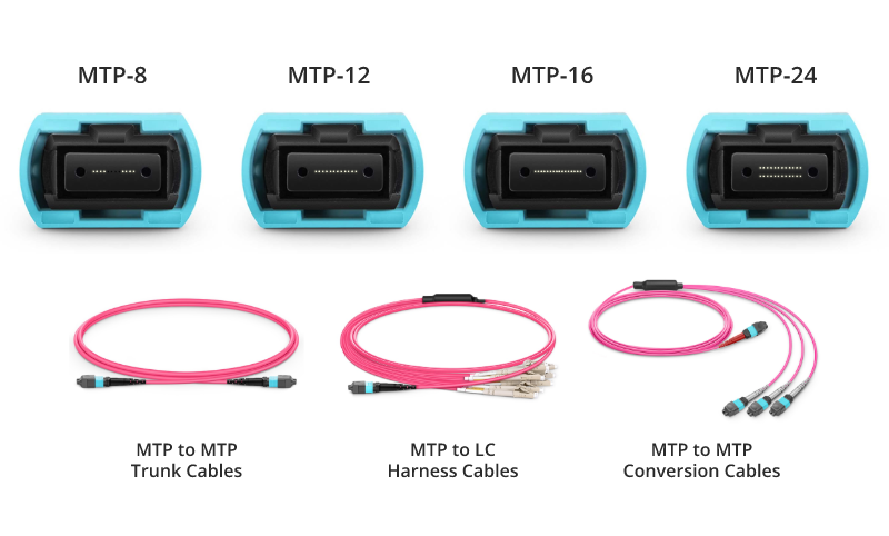
MTP/MPO cables consist of connectors and optical fibers ready to connect. When it comes to types, MTP/MPO fiber cables fall on MTP/MPO trunk cables and MTP/MPO harness/breakout cables.
MTP/MPO trunk cables
MTP/MPO trunk cables, typically used for creating backbone and horizontal interconnections, have an MTP/MPO connector on both ends and are available from 8 fibers up to 48 in one cable.
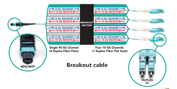
MTP/MPO Harness/Breakout Cables
Harness/Breakout cables are used to break out the MTP/MPO connector into individual connectors, allowing for easy connection to equipment. MTP/MPO conversion cables are used to convert between different connector types, such as MTP to LC or MTP to SC.
The MTP/MPO cables also come in different configurations, such as 8-core, 12-core, 16-core, 32-core, and more, depending on the specific needs of the application. This flexibility in configurations enables users to tailor their choices according to the scale and performance requirements of their networks or data centers. As technology advances, the configurations of MTP/MPO cables continually evolve to meet the increasing demands of data transmission.
How to Choose MTP/MPO cables
Selecting the appropriate core number for MTP/MPO cables resonates throughout the efficiency and performance of networks. In this section, we’ll delve into the decision-making factors surrounding core numbers in cables.
Network Requirements and Data Transmission Goals
Different network applications and data transmission needs may require varying numbers of cores. High-density data centers might necessitate more cores to support large-capacity data transmission, while smaller networks may require fewer cores.
Compatibility with Existing Infrastructure
When choosing the core number for MTP/MPO cables, compatibility with existing infrastructure is crucial. Ensuring that the new cables match existing fiber optic equipment and connectors helps avoid unnecessary compatibility issues.
Consideration for Future Scalability
As businesses grow and technology advances, future network demands may increase. Choosing MTP/MPO cables with a larger number of cores allows for future expansion and upgrades.
Budget and Resource Constraints
Budget and resources also play a role in core number selection. Cables with a larger number of cores tend to be more expensive, while cables with fewer cores may be more cost-effective. Therefore, finding a balance between actual requirements and the available budget is essential.
MTP/MPO Cabling Guide to Core Numbers
40G MTP/MPO Cabling
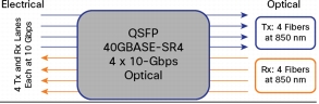
A 12-fiber MTP/MPO connector interface can accommodate 40G, which is usually used in a 40G data center. The typical implementations of MTP/MPO plug-and-play systems split a 12-fiber trunk into six channels that run up to 10 Gigabit Ethernet (depending on the length of the cable). 40G system uses a 12-fiber trunk to create a Tx/Rx link, dedicating 4 fibers for 10G each of upstream transmit, and 4 fibers for 10G each of downstream receive.
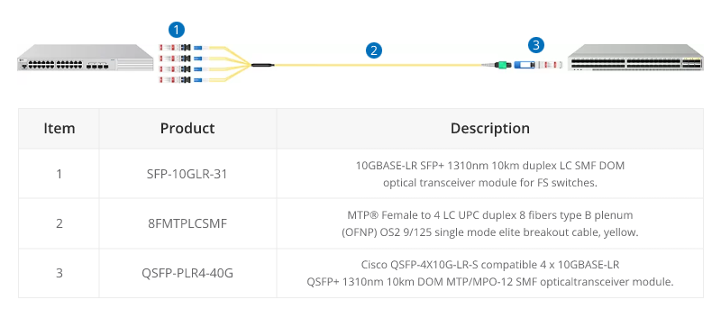
40G-10G Connection
In this scenario, a 40G QSFP+ port on the FS S5850 48S6Q switch is split up into 4 10G channels. An 8-fiber MTP-LC harness cable connects the 40G side with its MTP connector and the four LC connectors link with the 10G side.
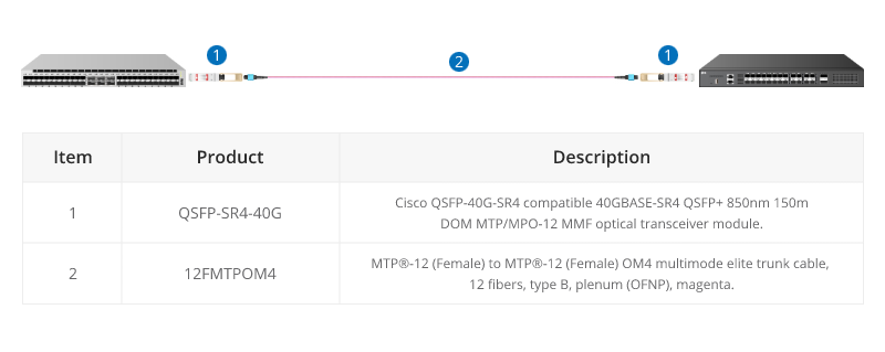
40G-40G Connection
As shown below, a 12-fiber MTP trunk cable is used to connect two 40G optical transceivers to realize the 40G to 40G connection between the two switches. The connection method can also be applied to a 100G-100G connection.
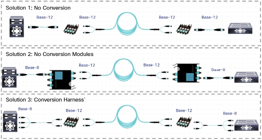
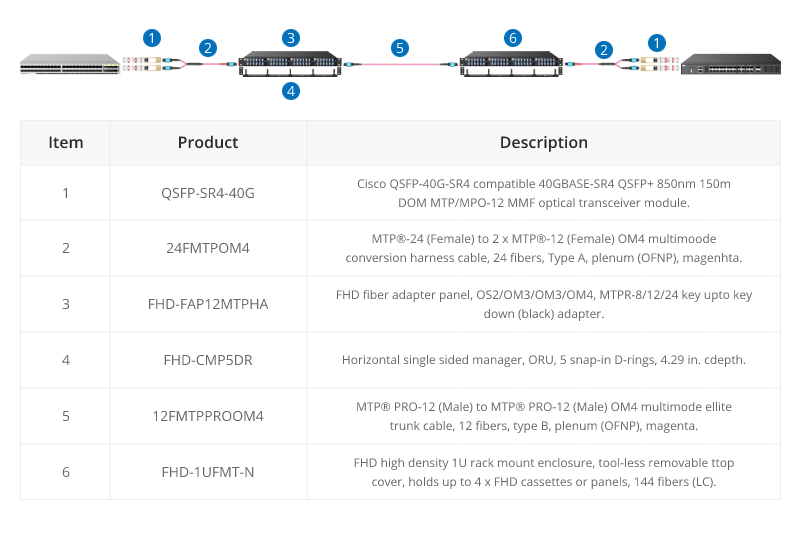
40G Trunk Cabling
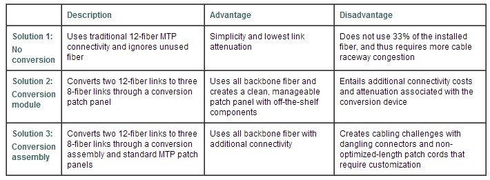
24 Fibers MTP® to MTP® Interconnect Conversion Harness Cable is designed to provide a more flexible multi-fiber cabling system based on MTP® products. Unlike MTP® harness cable, MTP® conversion cables are terminated with MTP® connectors on both ends and can provide more possibilities for the existing 24-fiber cabling system. The 40/100G MTP® conversion cables eliminate the wasted fibers in the current 40G transmission and upcoming 100G transmission. Compared to purchasing and installing separate conversion cassettes, using MTP® conversion cables is a more cost-effective and lower-loss option.
100G MTP/MPO Cabling
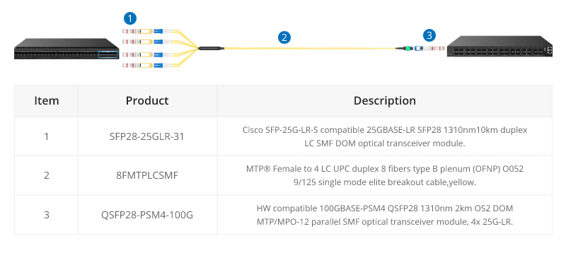
QSFP28 100G transceivers using 4 fiber pairs have an MTP/MPO 12f port (with 4 unused fibers). Transmission for short distances (up to 100m) could be done most cost-effectively over multimode fiber using SR4 transmission. Longer distances over single mode use PSM4 transmission over 8 fibers. Transmission over 4 fiber pairs enables both multimode and single-mode transceivers to be connected 1:4 using MPO-LC 8 fiber breakout cables. One QSFP28 100G can connect to four SFP28 25G transceivers.
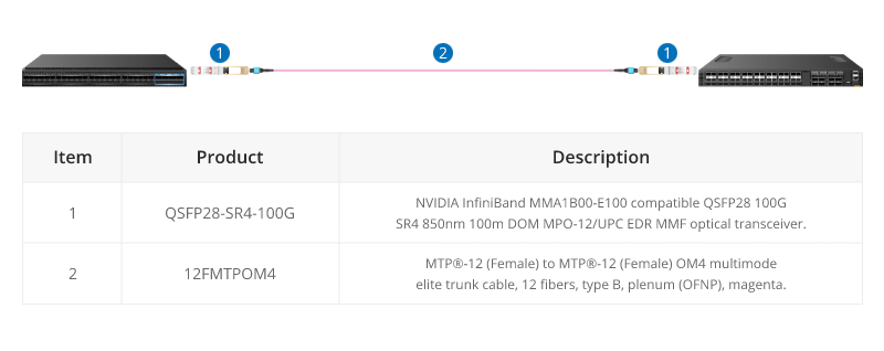
100G SR4 Parallel BASE-8 over Multimode Fibre
QSFP28 100G SR4 are often connected directly together due to their proximity within switching areas.
Equally QSFP28 SR4 are often connected directly to SFP28 25G ports within the same rack. For example, from a switch 100G port to four different servers with 25G ports.
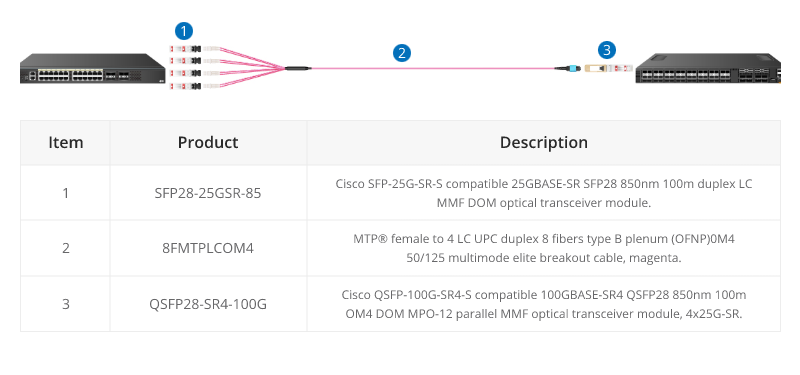
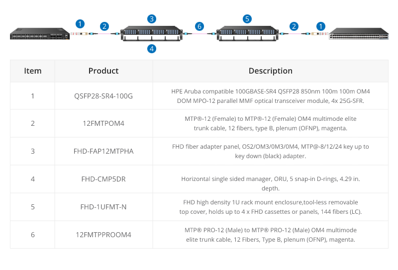
The 12-core MTP/MPO cables can also be used for 100G parallel to parallel connection. Through the use of MTP patch panels, network reliability is enhanced, ensuring the normal operation of other channels even if a particular channel experiences a failure. Additionally, by increasing the number of parallel channels, it can meet the continuously growing data demands. This flexibility is crucial for adapting to future network expansions.
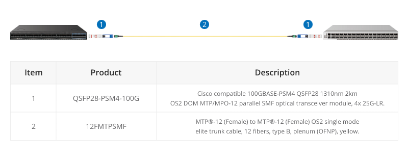
100G PMS4 Parallel BASE-8 over Singmode Fibre
QSFP28 100G PMS4 are often connected directly together due to their proximity within switching areas.
Equally QSFP28 ports are often connected directly to SFP28 25G ports within the same rack. For example, from a switch 100G port to four different servers with 25G ports.
200G MTP/MPO Cabling
Although most equipment manufacturers (Cisco, Juniper, Arista, etc) are bypassing 200G and jumping from 100G to 400G, there are still some 200G QSFP-DD transceivers on the market, like FS QSFP56-SR4-200G and QSFP-FR4-200G.
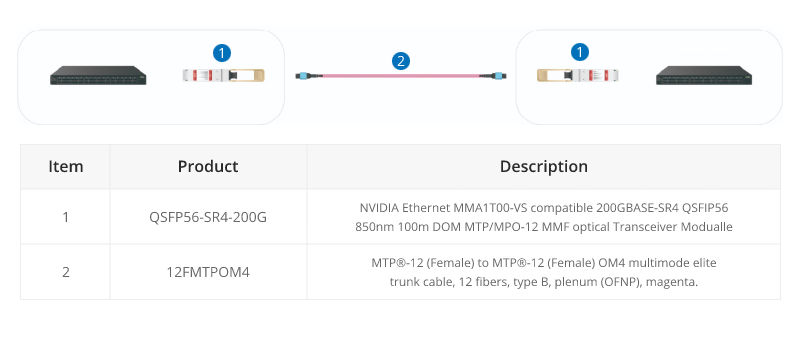
200G-to-200G links
MTP (MPO) 12 fiber enables the connection of 2xQSFP56-SR4-200G to each other.
400G MTP/MPO Cabling
MTP/MPO cables with multi-core connectors are used for optical transceiver connection. There are 4 different types of application scenarios for 400G MTP/MPO cables. Common MTP/MPO patch cables include 8-fiber, 12-core, and 16-core. 8-core or 12-core MTP/MPO single-mode fiber patch cable is usually used to complete the direct connection of two 400G-DR4 optical transceivers. 16-core MTP/MPO fiber patch cable can be used to connect 400G-SR8 optical transceivers to 200G QSFP56 SR4 optical transceivers, and can also be used to connect 400G-8x50G to 400G-4x100G transceivers. The 8-core MTP to 4-core LC duplex fiber patch cable is used to connect the 400G-DR4 optical transceiver with a 100G-DR optical transceiver.
For more specific 400G connectivity solutions, please refer to FS 400G MTP/MPO Cabling.
800G MTP/MPO Cabling Guide
In the higher-speed 800G networking landscape, the high density, high bandwidth, and flexibility of MTP/MPO cables have played a crucial role. Leveraging various branching or direct connection schemes, MTP/MPO cables are seamlessly connected to 800G optical modules, 400G optical modules, and 100G optical modules, enhancing the richness and flexibility of network construction.
800G Connectivity with Direct Connect Cabling
16 Fibers MTP® trunk cable is designed for 800G QSFP-DD/OSFP DR8 and 800G OSFP XDR8 optics direct connection and supporting 800G transmission for Hyperscale Data Center.
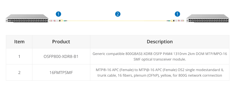
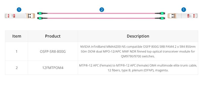
When using the current 800G optical module, such as the OSFP 800G SR8, direct connection requires 12 fibre MTP® trunk cables.
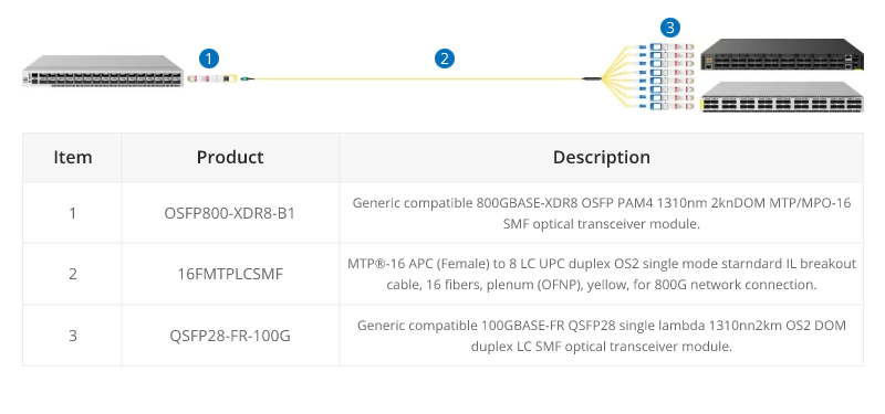
800G to 8X100G Interconnect
16 fibers MTP®-LC breakout cables are optimized for 800G OSFP XDR8 to 100G QSFP28 FR, 800G QSFP-DD/OSFP DR8 to 100G QSFP28 DR optics direct connection, and high-density data center applications.
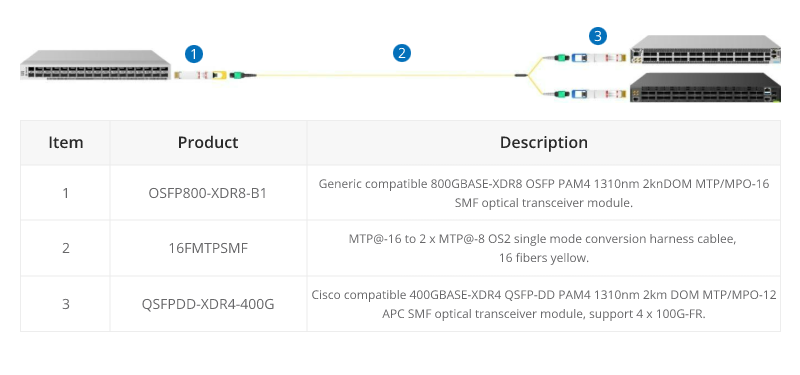
800G to 2X400G Interconnect
16 fiber MTP® conversion cable is designed to provide a more flexible multi-fiber cabling system based on MTP® products. Compared to purchasing and installing separate conversion cassettes, using MTP® conversion cables is a more cost-effective and lower-loss option. In the network upgrade from 400G to 800G, the ability to directly connect an 800G optical module and two 400G optical modules provides a more efficient use of cabling space, resulting in cost savings for cabling.
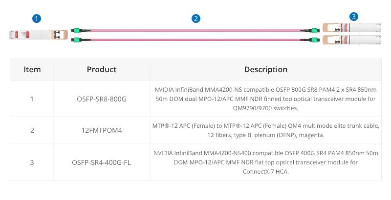
When using InfiniBand technology for networking purposes, 12 fibre MTP® trunk cable is designed for linking InfiniBand and Ethernet multimode twin-port OSFP and single-port OSFP and QSFP112 transceivers together.
Conclusion
In a word, the choice of core number for MTP/MPO cables depends on the specific requirements of the network application. Matching the core number with the requirements of each scenario ensures optimal performance and efficient resource utilization. A well-informed choice ensures that your MTP/MPO cable not only meets but exceeds the demands of your evolving connectivity requirements.
How FS Can Help
As a global leader in enterprise-level ICT solutions, FS not only offers a variety of MTP/MPO cables but also customizes exclusive MTP/MPO cabling solutions based on your requirements, helping your data center network achieve a smooth upgrade. In the era of rapid growth in network data, the time has come to make a choice – FS escorts your data center upgrade. Register as an FS website member and enjoy free technical support.