Options Upgrading to 100G Connection

With growing data traffic volume in recent years, the existing 10Gb/s optical networks are becoming saturated, which drive the great need for 40G and 100G networks. In turn, 100G network also can bring benefits for network operators. For example, 100G network can reduce the cost per bit, improve the utilization of existing fiber and reduce the network delay. This post intends to explore the options to get 100G connection.

100G Connectivity Challenges

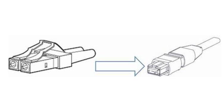
As we all know, existing 10G network use two fibers in either a SC duplex or a LC duplex connector to realize data transmission. But different from this transmit type, data in 100G network often get multiplexed and transferred over the 4 or 10 parallel wavelengths on a single fiber, which means the lanes of the two kinds of networks are a little different. This is one problem that should be considered when deploy 100G connections.

Except for that, the cost is another problem needed to be resolved. No matter the 40G or 100G, both of them require more fibers and optical connectors, resulting in increasing cost. For example, 40G Ethernet and 100G Ethernet over multimode fiber uses parallel optics at 10 Gb/s per lane. One lane uses one fiber for each direction of transmission. So 40G Ethernet requires eight fibers. And 100G Ethernet requires 20 fibers.

Options Upgrading to 100G Connections
Option One: Upgrading to 100G Connections with DWDM Mux

With the boom application of cloud services, telemedicine, video on demand, etc, data rate migration encompassing the entire optical network. Therefore, some core networks have deployed DWDM to release this bandwidth explosion. With large capacity transmission ability, DWDM technology offers a cost-effective method to meet the bandwidth requirements.

Complementing the existing 10Gbps DWDM system with 100Gbps upgrades

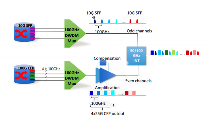
In many cases, to avoid the high cost and save cost, some operators often use one DWDM Mux to add one or more 100G services into the same fiber. The picture is showing one of that cases. In this case, 10G and 100G services are multiplexed by two separated 100GHz DWDM MUX. Owing to the 100G services are easy to be affected by dispersion, so the optical amplifier and DCM (Dispersion Compensation Module) are added in the links to boost the signal power. Then the 10G and 100G services are bundled together by using the interleaver which is an optical router often used in DWDM system. And finally the 100G connection is achieved.

Option Two: Upgrading to 100G Connections with MTP Assemblies

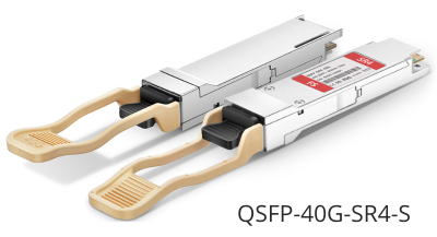
Nowadays there are various products on the market to support 100G connections. The most often used is 100G CFP, 100G QSFP28 and MTP optical cables. For many network operators, the option one that uses 100GHz DWDM Mux, optical amplifier, DCM and 100G optical transceivers maybe a little expensive. However, except for using DWDM Mux to achieve 100G connections, there is another choice. It is to achieve 100G connections with MTP assemblies.

100G Connection Deployment

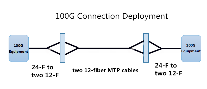
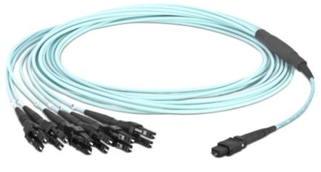
In this connection, the 100G connection can be realized by using a MTP cord with a 24-fiber MTP connector on one end and two 12-fiber MTP connectors on the other end.

Notes: this simple chart just illustrates a short distance 100G connection.

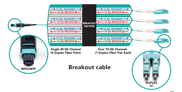
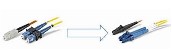
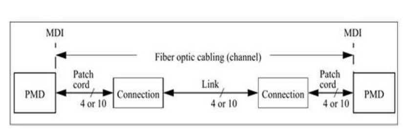
Besides, since 10G connections usually use common fiber optic cables with LC or SC connectors, and the 40G connections use 12-fiber MTP cables, while 100G connections utilize 24-fiber MTP connections. Therefore, migrating from 10G/40G to 100G can be realized. Look at the basic 10G and 40G deployment scenario.

10G 40G network deployment

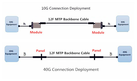
From the picture we can see, the similarities of these connections are that they are using MTP cables. Just change the cable types and then migrating from 10G to 40G and 100G are possible.

Summary

100G connection is the trend in the future data centers. This post introduces two options to achieve 100G connections with existing optical components. According to different requirements, you can choose a suitable solution. FS.COM supplies various optical components to meet diverse applications in data centers and enterprise networks. If you want to know more details about 100G networks, please visit our website www.fs.com.

Ruggedized Fiber Optic Cables for Harsh Environment

As a perfect choice for today’s telecommunication which requires a larger bandwidth, fiber optic cables have been widely put into use and get more popularity. However, when optical cables are increasingly used in different applications with diverse environments, for example, from indoor to tough environments, new and demanding requirements also have been put forward for them. Before deployment, several considerations may occur. For instance, can they resist the erosion of oil or chemicals? Can they still work normally in changeable weather? Do they have rodent-resistant ability? The answer of all the questions is yes. Today’s fiber optic cables possess various abilities to meet different requirements. Here is a brief introduction several ruggedized fiber optic cables that can work in different harsh environments, providing more conveniences and extra protection for network systems.

Armored Fiber Optic Cable

Armored fiber optic cable is one of the most commonly used cables to offer protection for fibers. Generally, armored fiber optic cable contains a helical stainless steel tap over a buffered fiber surrounded by a layer of aramid and stainless steel mesh with an outer jacket. With this unique construction, it can withstand the toughest environments—high temperatures, high pressures, and harsh vibrations as well as animals rodent and moisture. In a word, with the protection of flexible and durable steel tube, armored fiber patch cable will ensure the excellent operation of networks.

ruggedized-fiber-optic-cable-armored-cables

IP67 Waterproof Fiber Optic Cable

IP67 waterproof fiber optic cable is another kind of ruggedized cables used for outdoor applications. They are with strong PU jacket and stainless steel armor inside for future protection. “IP” in this term is a type of protection rating defined by International Standard IEC 60529. The number “6” and “7” mean this kind of cable possesses a good ability to resist dust and water. According to the connector types, the IP67 waterproof fiber optic cables have several types including IP67 MTP/MPO fiber cables, IP67 LC waterproof fiber cable and so on. IP67 waterproof fiber optic cables will not get damage even stepped, and are anti-rodents and suitable for use in harsh environment like communication towers and CATV (Community Antenna Television), providing protection for your networks. Here is a picture of IP67 LC component details.

ruggedized-fiber optic-cable-ip67-lc-commponent-details

Summary

With the rapid development of optical communication around the world, more and more fiber optic cables are increasingly used in different environments. Under harsh conditions, the ruggedness and durability of common fiber optic cables cannot meet operators’ requirements, especially for exceptional demanding applications. This post mainly introduces three types of ruggedized fiber optic cable. All the cables mentioned above are available in FS.com. If you have any problems about them, please contact us via sales@fs.com.

Effective Solutions for 10G/40G Connectivity

As the growing demand for faster access to larger volumes of data, coupled with emerging high-speed network standards and rapidly advancing technology, fiber optic cables and cabling components have become a very popular element in data centers and high-speed networks. And when 10G fiber is the norm in most data centers today, the 40G fiber is also becoming commonplace. In this article, three effective solutions for 10G/40G connectivity will be introduced.

Breakout Cabling Solutions

A breakout cable is a multi-strand cable which is divided into different specification cables. For example, a 40G breakout cable has four 10G duplex cables totaling eight strands, while a 100G breakout cable has 10 duplex cables and 20 strands.

How Does Breakout Cable Work?

To understand how breakout cabling solutions work, take integrating 10Gb servers into a 40G network for example. For each port on the switch, an MTP/MPO breakout cable which has an MPO/MTP connector on one end and four duplex LC connectors on the other end is needed. The MPO/MTP connector is plugged into the transceiver that connects with 40G switch and each duplex LC connector plugs into a 10G port on each server. If the switch has up to 32 40G ports, up to 128 10G devices can be connected to it using breakout cables.

breakout-cabling-solution

Advantages

This breakout cabling solution enables slower equipment to be connected to higher-speed equipment successfully, such as the 10G servers and 40G switch in our example. Up to 128 10G devices can be connected to a 32-port 40G switch.

MTP Cassettes Solutions

MTP cassette provide secure transition between MTP and LC or SC discrete connectors. They are used to interconnect MTP backbones with LC or SC patching. Supporting various network cabling standards, the cassettes are easy to mix, match, add and replace as the connectivity needs grow or change.

How Does MTP Cassette Work?

Fiber cassettes are the key to modular systems. Available in multiple variations, the cassettes allow users to interconnect different fiber speeds simply by plugging standard LC cables into one side of the cassette and one or more standard MPO/MTP cables into the other side.

modular-patch-panel-solution

For 10G connectivity, MTP/MPO cassettes are used to connect 10G device to 10G device, especially when the distance between two devices is too long. And for 40G connectivity, MPO/MTP cassette is used to connect 10G device to 40G device. Modular patch panel solutions offer users an easy-to-use solution that works with the equipment of today and can easily be transitioned for the networks of tomorrow.

Advantages

MTP cassette solution also has many advantages. First, this solution offers flexibility and scalability for network upgrade. Second, with fiber cassettes, this solution allows users to manage cables in any direction—horizontal or vertical, front or back. Finally, by managing varying port densities and speeds in a single high-density patch panel, users can save valuable rack space and data center costs.

Fiber Breakout Panels Solutions

Fiber breakout panels are ready for plug-and-play deployment out of the box. They provide increased access between ports, thus enabling the ease of moves, adds, and changes of cables. It’s the increased access that help fiber breakout panels offer a cost saving, simple and efficient cable management solution for future high-speed network connection.

How Does Breakout Panels Work?

Fiber breakout panels offer a simple, cost-effective alternative to breakout cables. To understanding how it works, let’s take one of 40G QSFP+ breakout patch panel for example. The 96 fibers MTP-LC 1U Ultra Density 40G QSFP+ breakout patch panel has 48 duplex LC ports front and 12 MTP Elite rear ports. When it’s installed, the 40G QSFP ports with MTP fiber cable will be connected to the back of the panel, and then LC fiber cables will be linked to the LC port. This 40G QSFP breakout panel logically groups the ports in 4 duplex LC ports, and is available for single-mode or multimode applications.

multimode-singlemode-fiber-breakout-panel

Advantages

Breakout panels solution can connect different equipment such as 10G, 40G and 100G, offering more flexibility for network cabling. Besides, as the breakout panels are pre-terminated, they can be easily installed and help save installation time.

Conclusion

With increasingly higher network speeds always just around the corner, network build and upgrade also get much attention. Choosing suitable connectivity solution for 10G/40G connectivity which allows you to meet your current connectivity needs while simultaneously investing in your future also should be attached more importance. The contents above give an explanation of three cabling solutions. Hope it may help you.

MPO/MTP Cable Assembly Solutions From FS.com

The increasing demands for high fiber counts and limited cabling space in today’s data centers have driven the evolution of multi-fiber technology. MPO/MTP technology with multi-fiber connectors serves as a practical optical solution to support high network performance in data centers to accommodate current and future requirements. Many MPO/MTP products are available in the telecommunication market, like MPO/MTP fiber cables, MPO/MTP cassettes, and MPO/MTP connectors. This article will introduce MPO/MTP cable assemblies and solutions in data centers.

MPO/MTP System Introduction

The term MTP is a registered trademark of US Conec used to describe their connector. MTP cable assemblies are designed and introduced as a performance version of MPO connectors. MTP does interconnect with the MPO connectors. Each MTP connector contains 12 fibers or 6 duplex channels in a connector that is smaller than most duplex connections in use today. A 72-fiber trunk cable can be terminated with six MTP connectors.

MPO/MTP fibers are manufactured with outstanding optical and mechanical properties, allowing high-density connections between network equipment. When easy insertion and removal of an MPO/MTP fiber is required, just a simple push-pull latching mechanism is used in manufacturing an MPO/MTP patch cord. That is called the Push-Pull tab MPO patch cord. This kind of MPO patch cord with a Push-Pull tab offers maximum accessibility in high-density installations and easy insertion and removal with only one hand.

MPO/MTP Cable Assemblies Features

MTP brand cable assemblies are multi-fiber patch cords suitable for high-density backplane and PCB solutions. There are mainly two configurations for MTP cable assemblies. The most commonly used one is an MTP connector to MTP connector trunk cable that connects an MTP cassette to another MTP cassette. The other one is MTP connectors to LC or another connector.

MTP trunk cable, as a permanent link connecting the MTP modules, is available in 12-144 counts, intended for high-density applications. Using MTP trunk cables, a complete fiber optic backbone can be installed without any field termination.

MTP breakout cables, also known as harness cables, provide connection to equipment or panels that are terminated with LC, ST, and SC connectors. Such assemblies are available pre-wired into patch panels and wall enclosures, able to meet a variety of fiber cabling requirements.

MPO/MTP Cable Assemblies Applications

MPO/MTP cable assemblies are suitable for high-density switches to patching and distribution in data center applications. Their compact design addresses high fiber count applications with small and lightweight cables ideal for applications in which installation space is limited. Besides, the MPO/MTP connector is the standard for delivery of 40G (in its 12 fiber version) and 100G (in either a duplexed 12 fiber cable or 24 fiber ferruled cable) using QSFP transceivers. In 40G applications, take QSFP-40G-SR4-S for instance, this Cisco QSFP-40G-SR4-S QSFP+ transceiver establishes 40G links with the 12 fiber MPO connector assembly.

About FS.com MPO/MTP Cable Assembly Solutions

As a leading fiber optical product manufacturer and supplier, as well as a third party, FS.com follows customers closely to understand their tastes and better meet their requirements. FS.com supplies high-quality MPO/MTP assemblies available in both single-mode and multi-mode versions, in the trunk and fan-out types, which are sold at competitive prices. Besides, the Push-Pull tab MPO patch cord (one type of Push-Pull patch cord), which allows easy installation and removal of cables, can also be found on FS.com.

Conclusion

MTP/MPO cable assemblies help customers save time, space, and cost while providing high density, suitable for data centers, telecommunications, and broadcast communication applications. On FS.com, you find the right MTP/MPO cable assemblies for your network performance. Additionally, these products can also be customized upon your request. You can visit FS.com for more information about MTP/MPO cable assembly solutions.

Attention: The products mentioned in this article may have unstable availability due to timeliness. For more information, please visit www.fs.com and consult our online customer service.

MPO/MTP Fiber Cabling Basics

With the ever increasing need for even greater bandwidth in data centers, multi-mode fiber cables (MMFs) have proven to be a practical optical solution to support such fast-changing and fast-growing bandwidth demand. MTP/MPO fiber cabling, ideal for quick and reliable MMF connectivity, provide an effective way for 40GbE network solutions, ensuring a high-performance and high-speed network. This blog includes basic information about MPO/MTP fiber cabling solutions.

MTP/MPO Connector Background

The term MTP is a registered trademark of US Conec used to describe their connector. The US Conec MTP product is fully compliant with the MPO standards. As such, the MTP connector is a MPO connector.

MTP/MPO Fiber Cabling System Introduction

MTP/MPO fiber cables, as an important part of the MPO/MTP cabling system, are designed to go on reliable and quick operations for the multi-fiber connection system in data centers. Each MTP fiber cable contains 12 fibers or 6 duplex channels in a connector, thus requiring less space. Besides, MTP/MPO fibers are manufactured with outstanding optical and mechanical properties, which makes them able to offer more improved scalability. What’s more, it is easy to have cable management and maintenance on them. Generally speaking, MTP/MPO fiber cables can save a lot of money and space to some extent.

MTP/MPO Fiber Cabling Categories

When it come to types, MTP/MPO fiber cables fall on MTP/MPO trunk cables and MTP/MPO harness cables.

MTP/MPO trunk cables, available in 12-144 counts, are intended for high-density application. By using MTP/MPO trunk cables, the installation of a complete fiber optic backbone is accessible without any field termination.

MTP/MPO harness cables, also called MTP/MPO breakout cables or MTP/MPO fanout cables, available in 8-144 counts, are used for breaking out the MTP into several connections. They provide connection to equipment or panels that are terminated with other standard connectors. As terminated with MTP/MPO connectors on one end and standard LC/FC/SC/ST/MTRJ connectors (generally MTP to LC) on the other end, these cable assemblies can meet a variety of fiber cabling requirements.

MPO/MTP Fiber Cabling for 40GbE

The Institute of Electrical and Electronics Engineers (IEEE) 802.3ba 40 Ethernet Standard was ratified in June 2010. The IEEE 802.3ba standard specifies MPO connectors for standard-length MMF connectivity. MMF employs parallel optics using MPO interconnects for 40GbE transmission. More specifically, 40G is implemented using eight of the twelve fibers in a MPO connector. Four of these eight fibers are used to transmit while the other four are used to receive. Each Tx/Rx pair is operating at 10G.

FS MPO-based fiber cabling solutions provide a fast, simple, and economical way for 40G applications. Certainly, FS 40G fiber cabling solutions are not limited to MPO/MTP fiber cables. Copper cables are also recommended. Take CAB-Q-Q-1M for example, Arista CAB-Q-Q-1M is the QSFP+ to QSFP+ passive copper cable assembly for 40G links. One of the other FS 40G fiber cabling products: JG329A, FS compatible HP JG329A runs over passive breakout copper cable for 40-gigabit link.

Conclusion

High-density MTP/MPO fiber cabling plays a significant part in cabling structure, suitable for telecommunications. FS provides both single-mode and multi-mode MPO and MTP fiber cables, as well as other MTP/MPO cable assemblies, including trunk cables, harness cables and cassettes. Customized products are also available upon your request. For more information about MPO/MTP fiber cables as well as 40G fiber cabling products (like Arista CAB-Q-Q-1M and HP JG329A mentioned above), please visit FS.com.

The Anatomy of MPO Trunk Cable Assembly

New cable designs are being developed to address the specific needs of connectorized cable assemblies. There are various industry-standard tests that evaluate the mechanical and environmental performance of cables and another set of standard tests for connectorized assemblies. In many cases, there are choices made in the cable design parameters, which may affect the cable assembly process, without due consideration of the complications that might be added to the assembly processes. Over the past few years, manufacturers have sought to co-develop new cables and the associated cable assemblies, which improve both the performance and processing of the assemblies. Here we report the development of innovative new trunk cables and associated cable assemblies.

Fiber optic cables are designed to meet rigorous standards for cable performance. These requirements include mechanical and environmental testing such as long length tensile testing and temperature cycling. A successful design is judged by how well it meets these requirements. The cable manufacturer then sells the cable to an assembly manufacturer that will furcate and connectorize the fibers from the cable to make a cable assembly.The furcation removes the outer jacket of the cable and prepares the fibers to receive a connector. Additionally, the furcation terminates the cable strength members and must isolate fiber strain in the cable from the connector. The furcation process may include adding a protective furcation leg over the fibers to provide protection between the end of the cable jacket and the connector. The design of the cable has a significant impact on the design and complexity of the furcation. The objective of this effort was to re-design the cable assembly to improve furcation processing and add customer preferred features to the trunk cable assembly.

Traditional high fiber count trunk cable assemblies have been made with fire retardant ribbon cables. These cables have the advantage that the fiber optic ribbons easily mate to the 12-fiber MPO connectors. The MPO connectors are preferred by customers because they allow quick and easy connection of the trunk cables to the MPO/LC breakout modules in a patch panel. However, the rectangular furcation legs have significant preferential bending which may be bothersome during installation. The ribbon trunk cables have several characteristics that may beaggravating during cable assembly and installation. The cables have a ribbon stack contained within a hard plastic buffer tube that is surrounded by tensile yarn and an outer jacket. This design provides a robust cable but makes a fairly stiff cable with a large bend radius,which may be difficult to route during installation. Furthermore, the cable design drives the requirement for a large furcation plug and pulling grip that requires more space for pulling the cable in during installation.

ribbon cable

Cables utilized in preterminated assemblies come in many varieties, but there are some common features to all cables. Cables consist of optical fibers, strength members and an outer protective jacket. The cable designs considered in this work were ribbon cables and non-ribbon cables. Each design used 250 µm colored optical fibers. The ribbon cables had the fibers grouped in a linear array with 12 fibers per ribbon. The unitized cables consist of individual units that contain 12 fibers and aramid yarn. One benefit of using ribbon cable is that the installation of multi-fiber connector is simplified because it is not necessary to group the fibers in such an array to install them into the MPO connector. One detriment of the ribbon cable design is that it necessitates rectangular legs to protect the ribbon in the transition from the furcation to the connector. An advantage of unitized cables is that they enable the use of round furcation legs or, with properly designed cable and furcation, the use of the subunits as the legs themselves. Now the following is the introduction of 12-fiber and 24-fiber trunk cable Assemblies.

trunk cable

MPO Trunk Assemblies are pre-terminated 12-fiber and 24-fiber cable assemblies. The unique design of the MPO Connector allows for rapid gender and polarity change in the field, in support of standards-compliant cable plant migration from 10G cassette-based systems to 40G MPO connector-based parallel optics cable plant. These trunk cable assemblies optimize cable routing requirements to ensure efficient use of pathway space and significantly reduce installation time and cost. All small diameter trunk cable assemblies are factory terminated and tested to deliver verified optical performance and reliability for improved network integrity. 10Gig versions provide 10 Gb/s network performance up to 300 meters for OM3 and up to 550 meters for OM4 per IEEE 802.3ae 10 GbE standard while maintaining compatibility with legacy systems.

10G fiber backbone or permanent link when mated to MTP Cassettes or fiber adapter panels paired with MPO to LC breakout harnesses. Method A and Method B TIA 568-C compliant for 40G parallel optics multimode applications. Allows system designers to tailor configuration, reach and breakout construction to application requirements; to minimize waste, optimize cable management, speed deployment, improve flexibility and manageability for lower installation costs. Small diameter trunk cable assemblies use 30 – 40% less space which is ideal for high cable density applications.

The Development and Application of MPO/MTP Multi Core Fiber Connector

MPO / MTP high-density fiber optic connection system is currently used mainly for three pre areas: Application of high-density data center environments, application of fiber to the building, application of internal connections in the splitter, 40G, 100G SFP, SFP + optical transceiver equipment, etc. This article highlights why the data center uses an MPO / MTP high-density fiber optic cable connection system and how to choose this high-density fiber optic connection system.

In the communications, and data transmission field, the development of fiber optic connectors is more prolific than copper connectors. According to incomplete statistics, so far, fiber optic connectors developed hundreds of different kinds, but only a dozen can be widely used. Fiber optic connector has two distinct stages of development. In the first stage, to save space, and develop miniaturization, the fiber optic connector is from traditional FC, ST, and SC connectors to LC, and MTRJ.

sc fiber patch

SC fiber patch cables

The second stage is not only to save space but also to meet the requirements for the use of multi-core, fiber optic connectors evolved from LC, MTRJ, E2000 to MU, MTP/MPO, now an MTP / MPO connectors can meet the 2 core, 4 core, 8 cores, 12 cores, 24 cores, up to 72 core requirements.

Fiber optic  patch cord

Fiber optic patch cord

It has been the last few years that the MPO MTP Fiber pre-connected system used in the data center. Why not the MPO / MTP pre-connected systems widely used? First, data center space is never enough. To solve the shortage space can increase the space or improve the utilization of space. It is unrealistic in a designed data center, Improvement of space utilization is to increase density. The two major data center cabling systems: are copper and fiber optic cable. Copper systems can use high density, but this high density is limited to space-saving. It is not only to satisfy the high frequency but also to find a balance between the larger line through. So in the same space to get more bandwidth, using optical transmission is an inevitable choice, but this does not necessarily require a high-density fiber optic connection system.

Secondly, the result of network speed and improvement, in terms of fiber optic, core fiber can support the application of 100MB, 1000MB, and 10000MB. More than 200 experts FS working group launched an application to support this standard. In the following chart, we can see a single channel or 4-core 10-core optical fiber, normal 40G and 100G fiber optic network communications are 8-core and 20-core optical fiber. This challenges traditional dual-core optical fiber transmission, it requires to use of a high-density multi-core optical fiber.

Fiber optic cabling

Fiber optic cabling

How do guarantee the performance of pre-connected high-density MTP/MPO fiber optic system products in the factory? What is different from common fiber optic cables?

First, the company must meet the ISO9000 series of quality management system certification, and production process and product performance also meet certification standards of the most comprehensive and the most stringent of fiber optic connector assembly production. Now many factories can produce fiber optic cables.

For another, understanding the MPO MTP Fiber system products, whether polarity module or truck fiber cable, whether fiber optic harness or MPO Fiber cable is more complex than SC and LC fiber.

Lastly, this article discusses the reason for using an MPO / MTP high-density fiber optic connection system and gives some advice for this new system, FS hopes it is helpful to the users of data centers and the same occupation.