Options Upgrading to 100G Connection

With growing data traffic volume in recent years, the existing 10Gb/s optical networks are becoming saturated, which drive the great need for 40G and 100G networks. In turn, 100G network also can bring benefits for network operators. For example, 100G network can reduce the cost per bit, improve the utilization of existing fiber and reduce the network delay. This post intends to explore the options to get 100G connection.

100G Connectivity Challenges

As we all know, existing 10G network use two fibers in either a SC duplex or a LC duplex connector to realize data transmission. But different from this transmit type, data in 100G network often get multiplexed and transferred over the 4 or 10 parallel wavelengths on a single fiber, which means the lanes of the two kinds of networks are a little different. This is one problem that should be considered when deploy 100G connections.

Except for that, the cost is another problem needed to be resolved. No matter the 40G or 100G, both of them require more fibers and optical connectors, resulting in increasing cost. For example, 40G Ethernet and 100G Ethernet over multimode fiber uses parallel optics at 10 Gb/s per lane. One lane uses one fiber for each direction of transmission. So 40G Ethernet requires eight fibers. And 100G Ethernet requires 20 fibers.

Options Upgrading to 100G Connections
Option One: Upgrading to 100G Connections with DWDM Mux

With the boom application of cloud services, telemedicine, video on demand, etc, data rate migration encompassing the entire optical network. Therefore, some core networks have deployed DWDM to release this bandwidth explosion. With large capacity transmission ability, DWDM technology offers a cost-effective method to meet the bandwidth requirements.
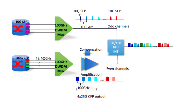
Complementing the existing 10Gbps DWDM system with 100Gbps upgrades

In many cases, to avoid the high cost and save cost, some operators often use one DWDM Mux to add one or more 100G services into the same fiber. The picture is showing one of that cases. In this case, 10G and 100G services are multiplexed by two separated 100GHz DWDM MUX. Owing to the 100G services are easy to be affected by dispersion, so the optical amplifier and DCM (Dispersion Compensation Module) are added in the links to boost the signal power. Then the 10G and 100G services are bundled together by using the interleaver which is an optical router often used in DWDM system. And finally the 100G connection is achieved.

Option Two: Upgrading to 100G Connections with MTP Assemblies

Nowadays there are various products on the market to support 100G connections. The most often used is 100G CFP, 100G QSFP28 and MTP optical cables. For many network operators, the option one that uses 100GHz DWDM Mux, optical amplifier, DCM and 100G optical transceivers maybe a little expensive. However, except for using DWDM Mux to achieve 100G connections, there is another choice. It is to achieve 100G connections with MTP assemblies.
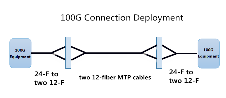
100G Connection Deployment

In this connection, the 100G connection can be realized by using a MTP cord with a 24-fiber MTP connector on one end and two 12-fiber MTP connectors on the other end.

Notes: this simple chart just illustrates a short distance 100G connection.

Besides, since 10G connections usually use common fiber optic cables with LC or SC connectors, and the 40G connections use 12-fiber MTP cables, while 100G connections utilize 24-fiber MTP connections. Therefore, migrating from 10G/40G to 100G can be realized. Look at the basic 10G and 40G deployment scenario.
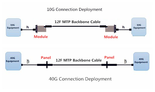
10G 40G network deployment

From the picture we can see, the similarities of these connections are that they are using MTP cables. Just change the cable types and then migrating from 10G to 40G and 100G are possible.

Summary

100G connection is the trend in the future data centers. This post introduces two options to achieve 100G connections with existing optical components. According to different requirements, you can choose a suitable solution. FS.COM supplies various optical components to meet diverse applications in data centers and enterprise networks. If you want to know more details about 100G networks, please visit our website www.fs.com.

Fiber Optic Cable Handling Rules

Contaminated fiber optic cables can often lead to degraded network performance or even failure of the whole system. As such, to ensure that fiber optic cables can yield the best possible results of network performance, and it’s of great significance for network engineers to keep in mind how to handle fiber optic cables. Do you have any ideas? This text gives the guide to fiber optic cable handling rues.

Fiber Optic Cable Elements

Before delving into how to handle fiber optic cables, introduction to their makeup elements is required.

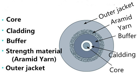
fiber optic cable fiver elements

Fiber optic cable generally consists of fiver elements (figure shown above): the optic core, optic cladding, a buffer material, a strength material and the outer jacket. Commonly made from doped silica (glass), the optic core is the light-carrying element at the center of the cable. Surrounding the core is the optic cladding, whose combination with the core makes the principle of total internal reflection possible. Surrounding the cladding is a buffer material used to help shield the core and cladding from damage. A strength material surrounds the buffer, preventing stretch problems when the fiber cable is being pulled. The outer jacket is added to protect against abrasion, solvents, and other contaminants.

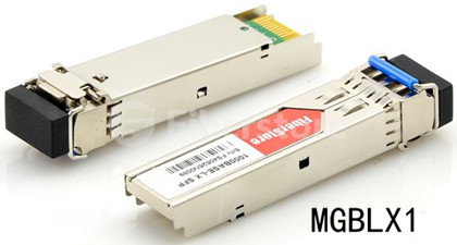
The outer jacket on fiber optic patch cord is often color-coded to indicate the fiber types being used. For instance, multi-mode fiber (MMF) is usually in orange to distinguish from the color yellow for single-mode fiber (SMF) through which fiber optic transceivers realize relatively long distance, such as MGBLX1. This Cisco 1000BASE-LX SFP transceiver is able to achieve 10km link length over SMF.

Cisco 1000BASE-LX SFP, SMF

Fiber Optic Cable Handling Rules

Despite its outer protection mentioned above, fiber optic cable is still prone to damage. In such as case, a series of fiber cable handing rules are made to ensure that a cable is handled properly, so as to maintain the optimized performance, minimum insertion loss and safe working environments.

Rule 1: The exposed fiber end from coming in contact with all surfaces should be protected. If you contact the fiber with hard surfaces, then the end of it shall be scratched or chipped, causing the degraded performance.

Rule 2: It’s highly recommenced to lean the connector (plug) end each time it is inserted into an adapter, since since a dirty connector will contaminate an adapter.

Rule 3: If a fiber needs to be pulled, use the connector strain relief. Directly pulling on the fiber may result in the glass breaking.

Rule 4: It’s ill-advised to use your hands to clean a fiber work area. If you use your hands to wipe clean a work area, a piece of glass may get lodged into your hands. Considering the size of the glass, this glass may not be visible to the naked eye, bringing about eye damage.

Rule 5: If possible, always keep a protective cap on unplugged fiber connectors, because covering the adapters and connectors will help to avoid contamination and collection of residue. Besides, store unused protective caps in a resealable container in order to prevent the possibility of the transfer of dust to the fiber. Locate the containers near the connectors for easy access.

dust cap covers for protection

Rule 6: It’s suggestible to use fiber-cleaning materials only once. If optic grade wipes are used to clean the fiber end, they should be discarded immediately after the fiber surface has been wiped to avoid contamination.

Rule 7: The minimum bend radius of the fiber optic cable must be maintained. Surpassing the bend radius may cause the glass to fracture inside the fiber optic cable. Equally, to cause a twist of the cable is also not proposed.

Rule 8: Never look into a fiber while the system lasers are on. Eye damage may occur if you stare directly at a fiber end which is working. Always make sure that the fiber optic cables are disconnected from the laser source, prior to inspection.

After discussion, these handling rules may help you to deal with fiber optic cables and improve your network performance.

Conclusion

Proper handling procedures for fiber optic cables are needed to eliminate the possibility of being contaminated or damaged, and provide a clean environment for the network system. Fiberstore supplies many different types of fiber optic cables with high quality for various applications, like MTP cable. You can visit Fiberstore for more information about fiber optic cables.