
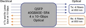
As previously mentioned, in 2010 IEEE 802.3ba approved the 40GBASE-SR4 physical-medium-dependent (PMD) multimode parallel optic solution, which uses eight fibers to transmit four duplex channels each at 10 Gigabit Ethernet. As shown in Figure 11, each transceiver transmits over four fibers and also receives transmissions over four fibers.
Also as previously mentioned, parallel optics does require a change from traditional cabling methods, which requires learning and so creates an incentive to move to the bidirectional solution at 40 Gigabit Ethernet. The main advantage of the parallel optics transceiver over the bidirectional transceiver at 40 Gigabit Ethernet is reach. For example, if you cable your data center with OM3 fiber at 10 Gigabit Ethernet, you can support distances up to 300m. Then if you move to 40 Gigabit Ethernet, you can support the same 300m distance with the same OM3 fiber and a 40GBASE-CSR4 transceiver. However, if your cabling distances do not justify the extra distance capability, then the bidirectional solution would be used (Figure 11).
The dilemma is that MTP cable assemblies, which have been used for more than a decade for cabling in the data center, are built on 12-fiber position connectors. Thus, each link has four unused fibers. There are several basic cabling options for parallel optics connectivity. One approach is to ignore the unused fibers and continue to deploy 12 fibers. Another approach is to use a conversion device to convert two 12-fiber links into three 8-fiber links. Three solutions exist (summarized in Table 7 and Figure 12).
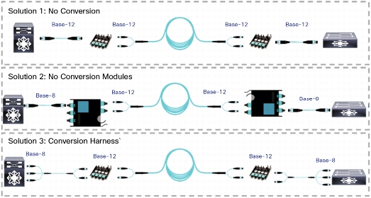
• Solution 1: The no-conversion scenario retains the whole 12-fiber based cabling system, but 33 percent of the fiber is not used. Additional cost is associated with the purchase of additional fiber, and your system includes unused fiber.
• Solution 2: This solution uses conversion modules to convert the unused fibers into useable optical links. For every two 12-fiber MTP connectors in the backbone cable, you can create three 8-fiber links. There is an additional cost for the additional MTP connectivity, but that is offset by the cost savings from 100 percent fiber utilization in the structured cabling. When you reuse existing deployed MTP cabling, you gain great value when you use the conversion module to use all previously deployed fiber, and you eliminate the cost of having to deploy additional cabling.
• Solution 3: This scenario uses standard MTP Cassette with a conversion assembly (two 12-fiber MTP connectors on one end going to three 8-fiber MTP connectors on the other end). This approach does not add any connectivity to the link, and it achieves full fiber utilization. However, although this approach may appear attractive, it involves considerable cabling challenges. For example, if you need only two 40-Gbps connections to a piece of equipment, what do you do with that third 8-fiber MTP connection? What if the 40-Gbps ports are in different chassis blades or completely different chassis switches? The result will be long assemblies, which will be difficult to manage in an organized way. For this reason, Solution 3 is expected to be the least desirable and so the least deployed method.
Table 7. Three Cabling Solutions for 40-Gbps Connectivity
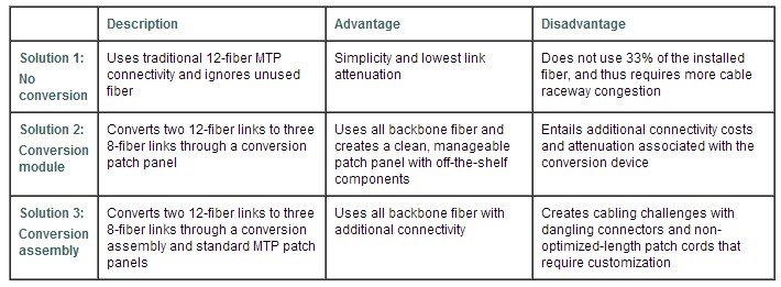
Figure 12. Cabling Solutions for 40-Gbps Connectivity
Fiberstore offers components to build all three solutions. However, Fiberstore suggests implementation of the conversion module solution, especially if you are using previously installed MTP trunks. This solution allows 100 percent fiber utilization while maintaining any port-to-any port patching. If you are installing all new cabling, then you could consider the no-conversion solution, assuming that the cable raceway is not a concern. Typically, the conversion harness is deployed only in specific applications, such as at the ToR switch, where 40-Gbps ports are in a close cluster and patching between blades in a chassis switch is not required.
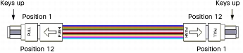
When directly connecting a parallel optics 40 Gigabit Ethernet transceiver to another 40 Gigabit Ethernet transceiver, a Type-B pinless-pinless MTP jumper should be used. As shown in Figure 13, a Type-B MTP jumper assembly, as defined in TIA-568-C.3, has the blue fiber 1 assembled in connector position 1 on one end of the assembly, and this same fiber assembled in connector position 12 on the other end of the assembly. This reverse fiber positioning allows the signal to flow from transmission on one end of the link to reception on the other end.
Figure 13. Type-B Array Patch Cord (per TIA-568-C.3)
This type of direct connectivity is suggested only within a given row of cabinets. The jumper assembly is tested only to the requirements of an interconnect cable, as defined in ANSI/ICEA S-83-596-2001. It has less robustness (less tensile strength, less crush and impact resistance, etc.) than a distribution-style cable, which would be used for structured cabling trunks.
Similar to the bidirectional cabling approach, the most basic structured cabling solution is an interconnect. The only difference between an interconnect solution and parallel optics is that the connector type of the patch panels instead is MTP. Figure 15 shows several interconnect link scenarios with various patch-panel options. As previously discussed, the 2×3 conversion modules, depicted in Figure 15a, allow 100 percent fiber utilization and constitute the most commonly deployed method. Another advantage of the conversion module is reduced jumper complexity. Notice that a G jumper, which has a Type-B polarity and is pinless, is used to directly connect two parallel optics transceivers. That same jumper is used on both ends of the interconnect link, thus eliminating concerns about correct pinning.
In Figure 15b, the same trunk is used, but the jumper type is now labeled F. In the bill-of-materials (BoM) shown in Table 8, you can see that an F jumper still has a Type-B polarity, but on one end the MTP is pinned and on the other end a pinless MTP is used. Thus, when you install the jumper, you would install the pinned end in the patch panel, and you would install the pinless end in the electronics. However, because of the pinning, this same jumper could not be used to make a direct connection between two ports. Hence, you can see the advantages of the conversion modules, which both use all the fiber and allow a single-jumper solution.
However, notice in Figure 16b that this is not the case for a non-conversion cabling scenario, in which standard MTP patch panels are deployed. Here the patch cords at the electronics are pinless (into the electronics) to pinned (into the patch panel), although the patch cords at the cross-connect are both pinned going into the patch panel. Thus, for a direct-connect, interconnect, and cross-connect cabling scenario, three different pinned jumpers are required.
An alternative approach is to install pinned MTP trunks in the structured cabling, but this approach can be used mainly in new installations because the traditional MTP trunks installed over the past decade have been pinless.
Structured cabling using an MTP cabling infrastructure can be used with current 10 Gigabit Ethernet environments while maintaining investment protection for 40-Gbps environments and beyond. With the new 40 Gigabit Ethernet bidirectional transceivers, no changes to the cabling infrastructure are required when transitioning from 10 to 40 Gigabit Ethernet. Extended 40 Gigabit Ethernet link distances, which match the distances at 10 Gigabit Ethernet, can be achieved by converting to parallel optics transceivers.
These transceivers require a change in traditional cabling practices. However, if structured cabling has been implemented with MTP-based trunk cables, then making the conversion is as simple as swapping the patch panels. Thus, the existing MTP-LC modules that were used in the two-fiber serial transmission would be replaced with MTP conversion modules for parallel optics.