Patch Panel vs Switch: What’s the Difference?

In network setups we see everything is plugged into a switch, but before that fiber cables are also connected to another supply – patch panel. Thus one question is often confusing: patch panel vs switch: What’s the difference and what’s the significant function of them respectively?

What Is Patch Panel?

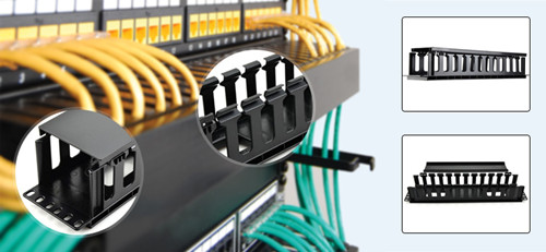
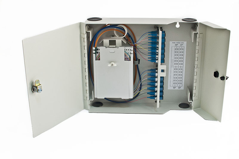
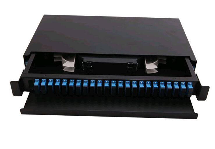
Patch panel (fiber optic patch panel, fiber optic enclosure) is a terminate unit of network ports centralized together. It is a cable management solution component used to organize fiber cables and keep everything neat for a clean wiring closet. In data centers, a mass of cable wires scattering all over and mixed together can be bothersome, in this case a patch panel is indispensable and rather helpful. It not only offers ease of management, but also protect the terminations from being knocked. Besides the fiber optic patch panel, other cable management accessories including cable ties and cable labels are also used to keep cables tidy and easy for identification.

patch panel vs switch: fiber optic patch panel

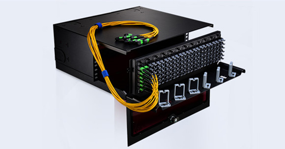
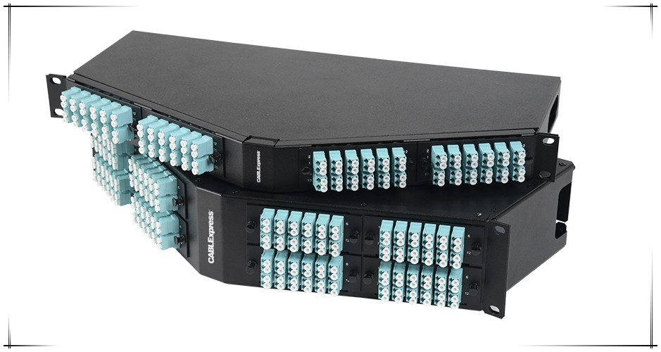
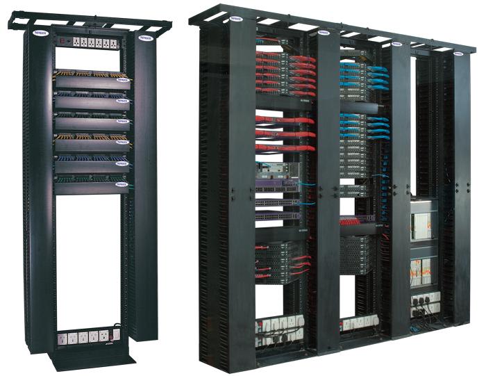
Figure 1: This photo shows the application of patch panel by FS.COM for cable management in a data center.

What Is Switch?

Switch, commonly known as network switch, is an appliance in a data center that connects all devices (such as PCs and servers) as a whole to achieve intercommunication and data sharing between different network devices. It channels the incoming data from multiple input ports to the specific output port so as to deliver the data toward its destination. In Ethernet LAN or WAN, modern network switch usually determines which output port to use by network address.

patch panel vs switch: network switch

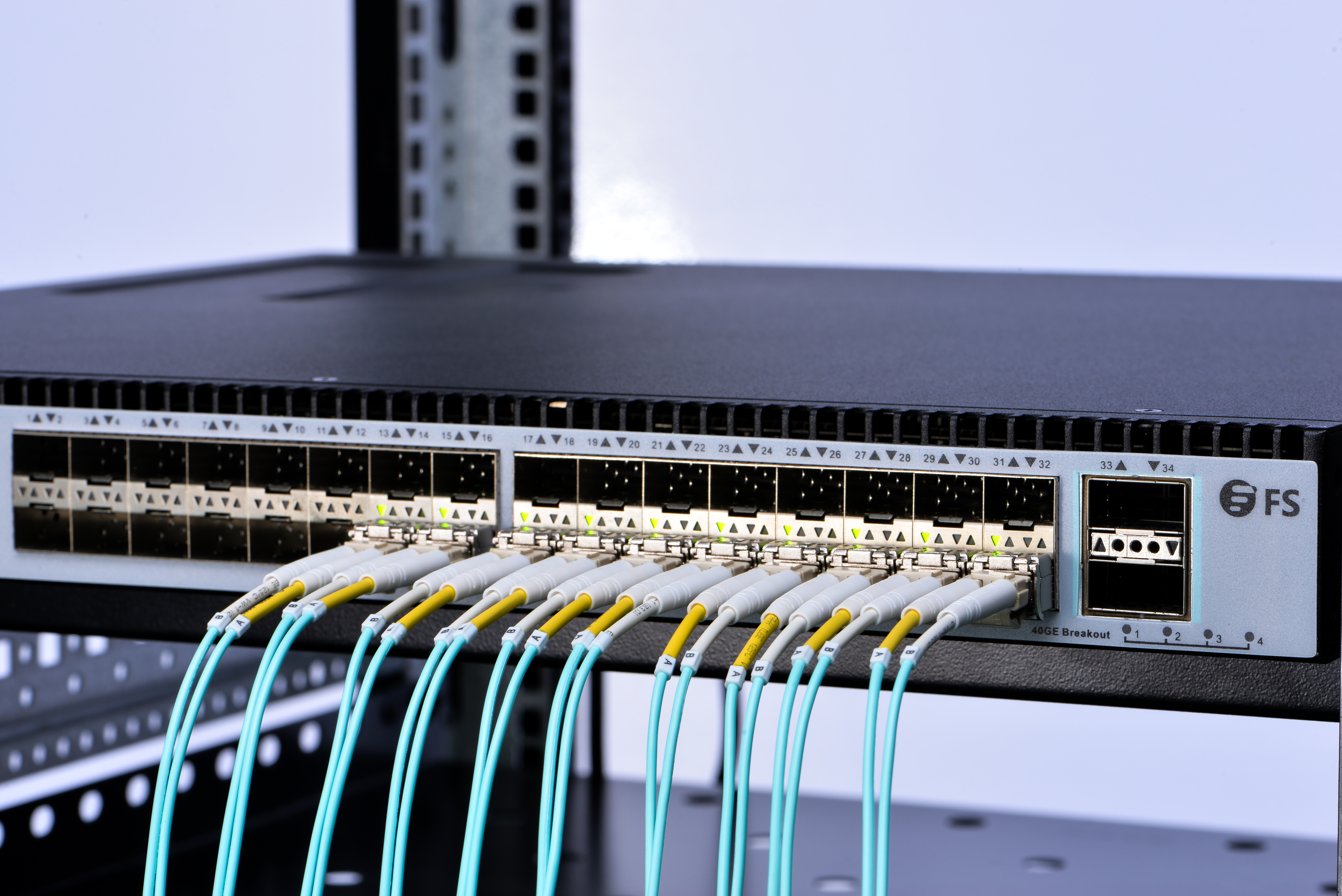
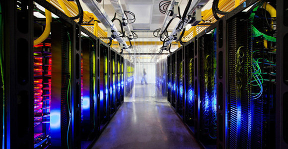
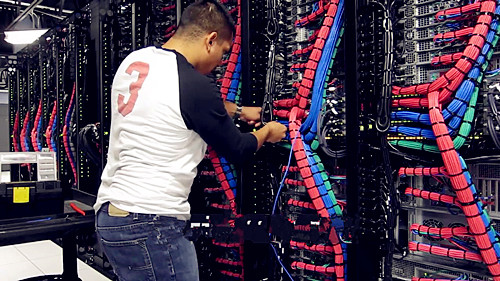
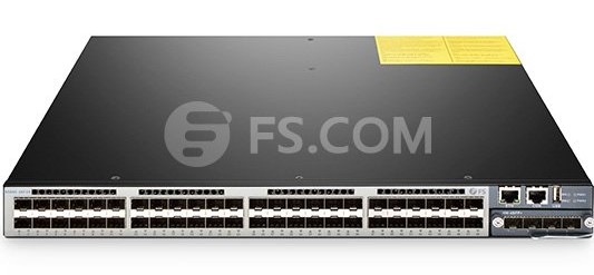
Figure 2: This photo shows the application of network switch by FS.COM in a data center.

Patch Panel vs Switch: What’s the Difference?

Table below shows the main difference of patch panel vs switch.

Name Patch Panel Switch
Price Cheap Expensive
Role playing Cable management tool:
Centralizing cable wires together; protecting fiber cables from damage.
Functional performance: connecting all devices together to receive and transmit exact messages to the target device end.
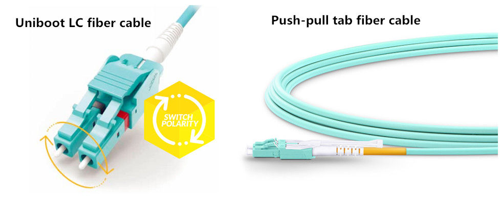
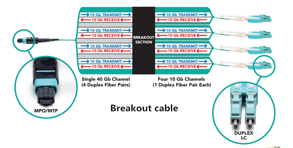
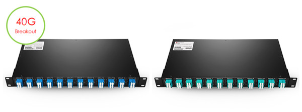
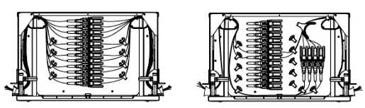
Form feature  fiber optic patch panel  network switch
·Role in Date Center

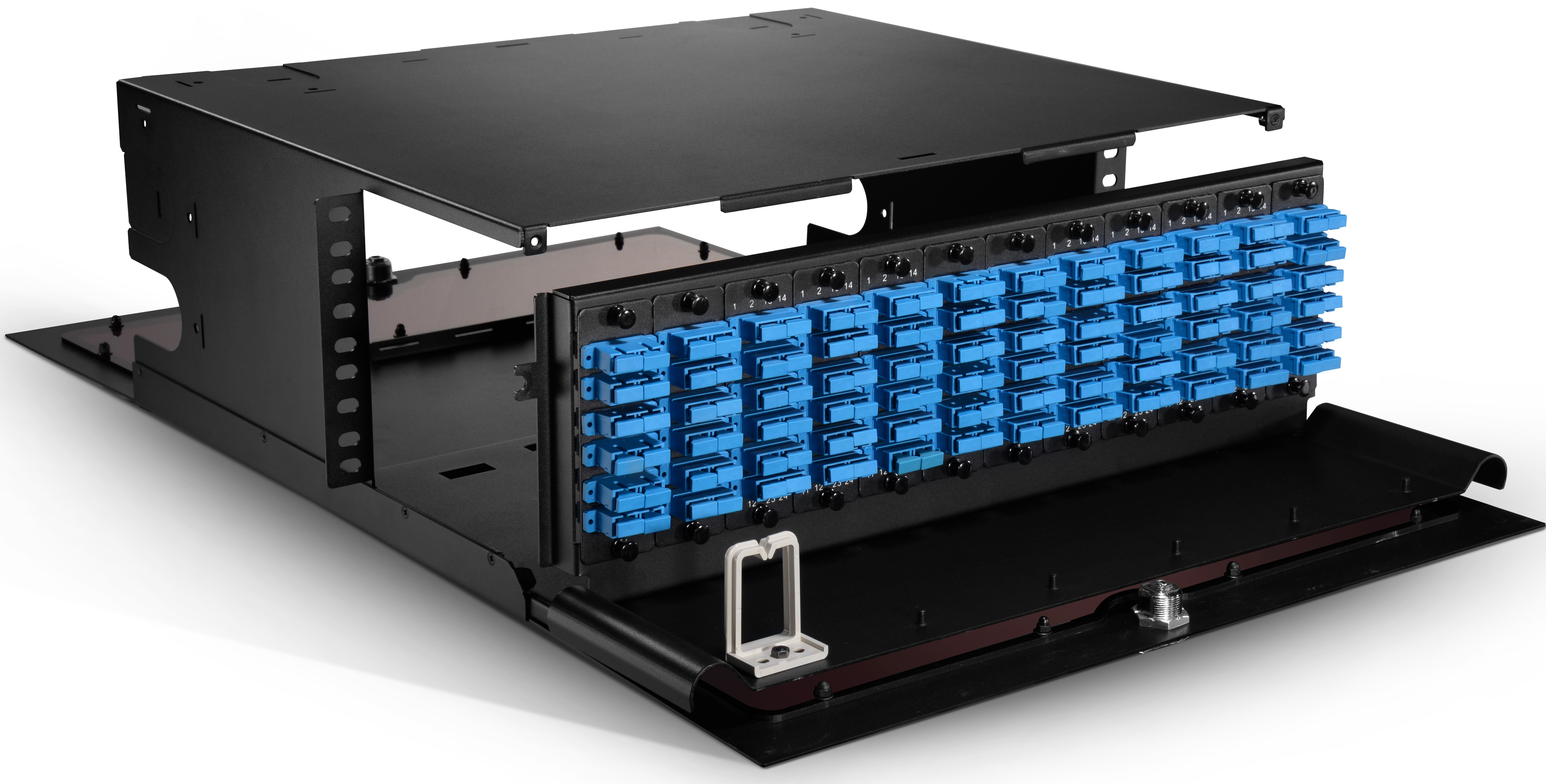
Comparing patch panel vs switch, we can make the following conclusion. Patch panel is nothing but an essential cable management tool, which exerts no functional influence to the performance of data transmission. However, a switch is an irreplaceable functional supply in network setups.

Why Patch Panel Is Commonly Set Up in Network Installation?

As mentioned above, patch panel has no effect on the data transmission process. Can it be omitted in fiber optic cabling? Or can wires just directly plugged to a switch? The answer is yes when you just deal with several fiber cables. However, Ethernet patch panel is a must in data centers where there are a large number of Ethernet drops. No doubt you don’t want to see all the things tangled together. A patch panel in place provide ease management of classification, maintenance, repair, installation and upgrades.

Conclusion

This article gave an brief introduction to patch panel and switch respectively and then discussed the differences between them. Patch panel vs switch : what’s the difference, and why is a patch panel commonly set up in network installation whereas a switch is already used? Can you answer these questions now? Simply put, patch panel is an essential cable management tool whereas network switch is a significant functional supply in data center. Both of them play important role in their respective positions.

Tips to Simplify Your Data Center Management

Data center houses a network’s most critical systems and is vital to the continuity of daily operations. Many of us have seen what it looks like. As we all know, the more complex a data center is, the more difficult it can be to ensure efficiency and orderly management—not only of the systems and equipment but of the working staff as well. How to simplify data center management? This post may give you the answer.

data center management

When several different types of product, tools, and resources are used to support a network, complication cannot be avoided. With the rapid development of society, many business demands require the data center to operate quickly and effectively. In order to achieve this goal, various mix-and-match occur, which lead to a complicated data center. Here are several tips to simplify data center management and make it work efficiently.

Emphasize Standardization

With the fast advancement of communications, equipment used in data centers is replaced frequently. Therefore, product standardization is something to keep in mind when upgrading and replacing the equipment, as well as the infrastructure that supports it. By utilizing standardized data center hardware, maintenance can be finished smoother and faster with common approaches, which save time, resources and money.

Choosing Easy Installation and Space-saving Components

A complicated data center environment makes it difficult to identify the root cause of errors or misconfigurations. So selecting some easy installation and space-saving products mean shorter installation times, less training time for staff and lower maintenance costs. There are many examples of products that make installation and maintenance simpler for data centers. Here are some examples.

LC Uniboot Patch Cable

Designed to deliver maximum connectivity performance in a minimal footprint according to standards, LC uniboot patch cable uses a single, unified jacket for both fibers. With this unique structure, it allows up to 68% space-saving in cabling volume, offering easier maintenance and operability. Besides, LC fiber optic connectors can offer higher density and performance in most environments, which makes it popular in many applications.

push-pull-tab patch cable

High-Density Push-pull Tab Fiber Optic Patch Cable

Push-pull tab patch cable has a special “pull” tab design that enables the connector to be disengaged easily from densely loaded panels without the need for special tools, allowing users easy accessibility in tight areas when deploying in data center applications. With this unique design, high-density optical cable, such as MTP/MPO fiber cable, offers high-density connections between network equipment in telecommunication rooms and data centers. They can be easily installed or removed with one hand, which improve efficiency greatly.

High-Density Fiber Enclosure

Fiber optic enclosures are designed to house, organize and manage fiber connections, terminations, and patching in all applications, providing the highest fiber densities and port counts in the industry contributing to better rack space utilization and minimizing floor space. Loaded with different numbers of FAPs, FHD fiber enclosures offer a high-density flexibility for cabling installations of data centers to maximize rack space utilization and minimize floor space.

4u fiber enclosure

Of course, except for the cables and enclosures mentioned above, other small components in data centers also cannot be ignored. For instance, cable ties and labels also play a critical role in cabling installations of data centers. In a word, every detail should be taken into consideration when managing a data center.

Preparing for Future-proof Cabling

As we have mentioned above, under this rapid development environment, data center management should be equipped to handle current needs while offering a clear path for future technology requirements. Complex data centers can be simplified when components are deployed that allow you to grow and migrate to new systems in the future without compromising performance or reliability. For example, solutions that offer support for both traditional ST and SC and modern LC and MPO applications support cost-effective, simpler migration to 40G and 100G applications with only a simple cassette or adapter frame change.

Summary

When data center processes and components are simplified, installation and maintenance for data center management become easier and less costly, staff resources are freed up for more strategic tasks, troubleshooting becomes less cumbersome and migration is also more easily achieved. All components mentioned above are available in FS.com. Welcome to visit our website for more detailed information.

Effective Solutions for 10G/40G Connectivity

As the growing demand for faster access to larger volumes of data, coupled with emerging high-speed network standards and rapidly advancing technology, fiber optic cables and cabling components have become a very popular element in data centers and high-speed networks. And when 10G fiber is the norm in most data centers today, the 40G fiber is also becoming commonplace. In this article, three effective solutions for 10G/40G connectivity will be introduced.

Breakout Cabling Solutions

A breakout cable is a multi-strand cable which is divided into different specification cables. For example, a 40G breakout cable has four 10G duplex cables totaling eight strands, while a 100G breakout cable has 10 duplex cables and 20 strands.

How Does Breakout Cable Work?

To understand how breakout cabling solutions work, take integrating 10Gb servers into a 40G network for example. For each port on the switch, an MTP/MPO breakout cable which has an MPO/MTP connector on one end and four duplex LC connectors on the other end is needed. The MPO/MTP connector is plugged into the transceiver that connects with 40G switch and each duplex LC connector plugs into a 10G port on each server. If the switch has up to 32 40G ports, up to 128 10G devices can be connected to it using breakout cables.

breakout-cabling-solution

Advantages

This breakout cabling solution enables slower equipment to be connected to higher-speed equipment successfully, such as the 10G servers and 40G switch in our example. Up to 128 10G devices can be connected to a 32-port 40G switch.

MTP Cassettes Solutions

MTP cassette provide secure transition between MTP and LC or SC discrete connectors. They are used to interconnect MTP backbones with LC or SC patching. Supporting various network cabling standards, the cassettes are easy to mix, match, add and replace as the connectivity needs grow or change.

How Does MTP Cassette Work?

Fiber cassettes are the key to modular systems. Available in multiple variations, the cassettes allow users to interconnect different fiber speeds simply by plugging standard LC cables into one side of the cassette and one or more standard MPO/MTP cables into the other side.

modular-patch-panel-solution

For 10G connectivity, MTP/MPO cassettes are used to connect 10G device to 10G device, especially when the distance between two devices is too long. And for 40G connectivity, MPO/MTP cassette is used to connect 10G device to 40G device. Modular patch panel solutions offer users an easy-to-use solution that works with the equipment of today and can easily be transitioned for the networks of tomorrow.

Advantages

MTP cassette solution also has many advantages. First, this solution offers flexibility and scalability for network upgrade. Second, with fiber cassettes, this solution allows users to manage cables in any direction—horizontal or vertical, front or back. Finally, by managing varying port densities and speeds in a single high-density patch panel, users can save valuable rack space and data center costs.

Fiber Breakout Panels Solutions

Fiber breakout panels are ready for plug-and-play deployment out of the box. They provide increased access between ports, thus enabling the ease of moves, adds, and changes of cables. It’s the increased access that help fiber breakout panels offer a cost saving, simple and efficient cable management solution for future high-speed network connection.

How Does Breakout Panels Work?

Fiber breakout panels offer a simple, cost-effective alternative to breakout cables. To understanding how it works, let’s take one of 40G QSFP+ breakout patch panel for example. The 96 fibers MTP-LC 1U Ultra Density 40G QSFP+ breakout patch panel has 48 duplex LC ports front and 12 MTP Elite rear ports. When it’s installed, the 40G QSFP ports with MTP fiber cable will be connected to the back of the panel, and then LC fiber cables will be linked to the LC port. This 40G QSFP breakout panel logically groups the ports in 4 duplex LC ports, and is available for single-mode or multimode applications.

multimode-singlemode-fiber-breakout-panel

Advantages

Breakout panels solution can connect different equipment such as 10G, 40G and 100G, offering more flexibility for network cabling. Besides, as the breakout panels are pre-terminated, they can be easily installed and help save installation time.

Conclusion

With increasingly higher network speeds always just around the corner, network build and upgrade also get much attention. Choosing suitable connectivity solution for 10G/40G connectivity which allows you to meet your current connectivity needs while simultaneously investing in your future also should be attached more importance. The contents above give an explanation of three cabling solutions. Hope it may help you.

How to Build Your Data Center?

Today’s data centers are complex. It houses dozens of diverse bandwidth-intensive devices tightly such as servers, clustered storage systems and backup devices, all of which are interconnected by cables. Therefore, the importance of a reliable, scalable and manageable cabling infrastructure is self-evident. Then how to build a data center which can meet today and future growth? This article may give you some advice about it.

5

How to Plan?

As data center houses a number of servers which are connected by numerous cables, it’s important to make it organized. If not, the last thing you will encounter is a tangled mass of cables that make it impossible to determine how severs are connected. Let alone to build a high-efficiency data center. Here are some tips on how to start your data center.

Using a Structured Approach

Using a structured approach to make data center cabling means designing cable runs and connections to facilitate identifying cables, troubleshooting and planning for future changes. In contrast, spontaneous or reactive deployment of cables that only suits immediate needs often makes it difficult to diagnose problems and to verify proper connectivity.

Using Color to Identify Cables

Colors can provide quick visual identification, which simplify management and can save your time when you need to trace cables. Color coding can be used ports on patch panels, color sleeves, connectors and fiber cables.

Establishing a Naming Scheme

Once the physical layouts of a data center are defined, applying logical naming will make it easy to identify each cabling component. Effective labeling brings better communications and can reduce unnecessary problems when locating a component. The suggested naming scheme often includes Building, Room, Grid Cell, Workstation, etc.

How to Select the Necessary Cabling Components?

After knowing how to construct the backbone network of a data center, selecting a right and suitable cabling components can quickly become overwhelming. Each cabling component has its own advantages and disadvantages. So it’s important to get the right equipment purchased and deployed to avoid future cabling problems. Below are some tips on how to choose corresponding cabling components.

Patch Panel

Patch panels enable easy management of patch cables and link the cabling distribution areas. How to choose a suitable one? First, the patch panels which allow different cable connectors to be used in the same patch panel are a good choice. Second, when choosing a patch panel, the main types of connectors within one panels are LC for fiber and RJ45 for copper. Finally, patch panels with colored jacks or bezels allow easy identification of the ports also can be taken into consideration.

angledpatchpanels

Cable Manager

Cable managers offer a neat and proper routing of the patch cables from equipment in racks and protect cables from damage. Generally, there are horizontal and vertical cable managers. And there are different requirements of these cable managers. When choosing horizontal cable managers, it’s essential to make sure that certain parts of the horizontal cable manager are not obstructing equipment in the racks and that those individual cables are easy to be added or removed. While choosing vertical cable managers, additional space used to manage the slack from patch cords is needed.

cable-management-panel

Cable Ties

Cable ties are used to hold a group of cables together or fasten cables to other components. Using cables ties can avoid crushing the cables and impacting cable performance. Velcro cable ties provided by Fiberstore are perfect for controlling and organizing wires, cords, and cables. Besides, using ties will help you identify cables later and facilitate better overall cable management.

cable-ties

Of course, except for what have been mentioned above, there are other cabling components which need to be selected carefully such as cable labels, backbone cables and so on.

What Should Be Paid Attention to When Installation?
  • Cabling installations and components should be compliant with industry stands.
  • Use thin and high-density cables wherever possible, allowing more cable runs in tight spaces.
  • Remove abandoned cables which can restrict air flow and may fuel a fire.
  • Keep some spare patch cables. The types and quantity can be determined from the installation and projected growth. Try to keep all unused cables bagged and capped when not in use.
  • Avoid routing cables through pipes and holes, which may limit additional future cable runs.
Summary

Building a data center is not an easy task. Each step and component selecting during installations need carefulness and patience. FS.COM provides all cable products including structured cables, patch panels, cable ties, labels and other tools needed in data center installation. All of them will maximize the efficiency and reliability of the data center installation.

How to Choose a Rack Cabinet

It is a commonplace nowadays to employ rack cabinets in data centers and other modern IT installations alike. Humble as the appearance is, rack cabinet actually plays a significant role in security and regulatory compliance, configurability, cooling and efficiency, as well as system availability. Moreover, it also helps to save much more space which is considered to be vital and precious for data centers. In this article, we will discuss how to choose a right rack cabinet that better fit your expectation.

What Is Rack Cabinet?

A server rack is a closed frame, specifically designed for holding monitors, servers, various networking equipment, electronic components, measuring instruments and other similar devices. Most commonly, the rack cabinets are installed for storing network equipment and servers. The rack cabinets provide an easy access to the networking equipment while enabling airflow, and they keep the working space well-organized.

rack cabinet

Rack cabinets are widely and intensively adopted to server rooms and data centers, audio/video installations, closets housing telecommunications equipment, and industrial environments such as a factory floor.

Common Types and Sizes of Rack Cabinet

Basically, there exist two types of rack cabinets in terms of different working conditions and requirements: floor standing rack cabinet and wall mount rack cabinet. If access control and equipment protection are important to you, floor standing rack cabinet is proved to be a desirable choice. While wall mount rack cabinet are ideal for securely housing IT equipment in classrooms or sites with limited floor space.

“Rack unit” is used to describe the height of a rack and the height of equipment in it. (a rack unit is 1.75 inches, or 44.45 mm). The actual height of a 42U rack is therefore 42 x 1.75 = 73.5 inches. A 2U server would occupy two of the available 42 rack units.

1 rack unit

Since the rack cabinet come in different sizes, when choosing a specified rack for your infrastructure you should at least take two factors into consideration: type of equipment to be stored inside and amount of space that is required. Be sure to make an accurate assessment of the amount of rack space you currently need, and allow for future growth.

In addition, before installing the rack cabinet, you need to make sure that the equipment to be placed in will match the rack cabinet. So the maximum rack depth required to mount your equipment should be taken into account. The rack depth of floor standing and wall mount rack cabinet is different, which will be explained in the following diagram.

Floor standing rack depth designation
Rack Depth (in.) Ideal for…
Shallow 27 A/V equipment, limited space
Mid-depth 31 Limited space
Standard 37 Servers
Deep 42 Extra cables, improved airflow
Wall mount rack depth designation
Rack Depth (in.) Ideal for…
Patch-depth < 16 Patch panels
Switch-depth 16-23.99 Switches
UPS-depth 24-31.99 UPS systems
Server-depth > 32 Servers
Benefits of Good Rack Cabinets

In terms of the benefits that every rack cabinet should provide, basically there are three main advantages:

Security—because the front and rear doors and side panels on most rack cabinets can be locked, access to equipment and sensitive data can be managed and controlled.

Great cooling flexibility—heat-sensitive equipment such as servers is isolated inside rack cabinets, allowing for more control over both active and passive airflow/cooling management.

Equipment protection from harsh environments—if your rack and equipment is going to be in harsh environments where dust, water and other debris could damage your equipment, a rack cabinet that protects equipment from the elements is for you.

Conclusion

IT infrastructure continues to expand and the need to organize, secure and cool servers, routers, hubs and PDUs is continuously increasing. Meanwhile, conserving space for future growth becomes more critical. All of these make rack cabinets an essential application in cutting-edge data center worldwide. I hope what we discussed above would assist you when you’re looking to purchase a rack to mount your servers and other network equipment.

Fiber Termination Box Overview

Fiber termination box (FTB), known as optical termination box (OTB) as well, is a compact fiber management product of small size. It is widely adopted in FTTx cabling for both fiber cabling and cable management. In some circumstances, fiber termination box can be regarded as the mini size of fiber optic patch panel and optical distribution frame (ODF).

Fiber Termination Box Classification

Currently, the market embraces a great amount of fiber optic termination boxes and other devices for cable management. And the names and model numbers of these fiber termination boxes vary from the design and idea of different manufacturers. Hence to identify the detailed classification of fiber termination box could be a hard task.

Roughly, fiber termination box can be categorized as fiber optic patch panel and fiber terminal box according to the size and applications. Judging by the appearance, fiber patch panel is of gibber size whereas fiber terminal box is smaller.

Fiber Patch Panels

Fiber patch panels are of wall mounted type or mounted type usually with 19 inch size. Generally, there is a tray inside the fiber box that helps to hold and protect the fiber links. Various different kinds of fiber optic adapters can be pre-installed in fiber patch panels as the interface, via which the fiber box could connect with the external devices.

Fiber Terminal Boxes

Besides fiber patch panels, one can also count on fiber terminal boxes for fiber distribution and organization. While typical fiber terminal boxes are with 12 ports or 24 ports, 8 ports, 36 ports, 48 ports and 96 ports fiber are available in the markets now. They are often installed with FC or ST adapters on the panel, either on the wall or put in horizontal line.

According to the design, FTB can be further divided into wall mount type and rack mount type.

The wall mount fiber termination boxes are designed for either pre-connectorized cables, field installation of connectors, or field splicing of pigtails. They offer an ideal solution for building entrance terminals, telecommunication closets, main cross-connects, computer rooms and other controlled environments.

wall mount FTB

The rack mount slide-out type fiber termination box usually for fiber splicing, distribution, termination, patching, storage and management in one unit. They support both cross-connect and interconnect architecture, and provide interfaces between outside plant cables and transmission equipment.

rack mount FTB

Moreover, in terms of installation environment, there are indoor FTB and outdoor FTB.

Indoor fiber termination box acts as the transition point between the risen cable and the horizontal cable, in this way, it provides operators much more flexibility when managing cables. Besides, indoor FTB makes it possible to leave space for overlength and terminated fibers, as well as for fiber splicing.

The outdoor fiber terminal boxes are environmentally sealed enclosures to distribute fibers for FTTX networks. They are also designed for fiber splicing, termination, and cable management.

Features of Fiber Termination Box

Fiber termination box contains the shell, the internals (supporting frame, set fiber disc, fixing device) and optical fiber joint protective element. Prominent advantages of fiber termination box lie in efficient cable-fixing, welding and its protective role in machinery of the optical fiber.

A insulation is always demanded between cable metal components and cable terminal box shell in a fiber termination box, which provides space for cable terminal and remained fiber storage. In addition, fiber termination box also facilitate the installation of different occasions since it is easy to access, which turns out to be time and cost saving.

Fiber Termination Box Application

Fiber termination box is universally used in telephone, agricultural telephone network system, data and image transmission system, CATV cable television series, indoor cable through force access and branch connection. Fiber termination box is available for the distribution and termination connection for various kinds of fiber optic systems, especially suitable for mini-network terminal distribution, in which the optical cables, patch cores or pigtails are connected. In addition to that, fiber termination box can be applied to joint fiber pigtail, protect fiber optic splices and share out the connectivity to individual customers.

Conclusion

Fiber termination box nowadays plays an indispensable role in the field of communication network with greater reliability and flexibility. This article may simply provide you a guideline when choosing fiber termination box for your infrastructure, for more detailed information and tutorial, please visit www.fs.com.

Related Article:1000BASE-X SFP Modules Overview

An Overview of Fiber Management Tray

Fiber management tray is generally adopted in the data center or server room for protection against the outside plant environment and damage. It serves as an economical approach for routing fiber cable, relieving the cable strain, handling and protecting fiber slack as well as accommodating fiber splice tray. The management tray has been designed to easily retrofit patch panel so as to make efficient cable management. Since the fiber management tray plays an indispensable role in the overall performance and reliability of the fiber optic cable, its importance thus cannot be ignored.

Why Use Fiber Management Tray

Optical transmission equipment nowadays can transmit astonishing amounts of data, video or telephone conversations. In addition, better technology has resulted in densely populated Fiber Optic Terminal (FOT) equipment frames. Both of these two factors make the fibers at the FOT very valuable. However, up to now, the emphasis on managing these fibers has been minimal.

An equipment frame may have only accommodated a few fibers in the past. Now these frames commonly accommodate 20, 40 or even 100 fibers. Consequently, it becomes even harder to quickly find the right fiber to change service than it used to be. If there comes the requirement to search for a fiber in a packed raceway, it is more likely that service on an adjacent fiber is disturbed. Therefore, physical protection is of significant importance for fibers entering and exiting the FOT. Besides, higher density and higher bandwidth dictate that complacency is no longer acceptable. Avoiding service outages mean managing and protecting fibers. Which testify the necessity and importance to employ management tray in fiber protection.

The Features of Fiber Management Tray

In this part, we will mainly discuss the features all-front access design tray and modular design tray.

The all-front access trays feature sliding radius limiters, which provide ultimate fiber management by addressing one of the most critical elements of fiber cable management: bend radius protection. When fibers leave the tray, a specially designed bell-shaped exit point provides maximum edge protection.In addition, by controlling the movement of fibers within the tray, error-proof slack loop management is maintained, ensuring 30mm bend radius protection within the tray, which is essential in ensuring no fiber breaks. Sliding adapter packs allow easy access for connecting jumpers and cleaning connectors, ensuring that any fiber can be installed or removed without inducing a macrobend on an adjacent fiber. Moreover, these trays are lockable, further ensuring the integrity of the fibers by reducing the chance of accident greatly.

The modular trays feature a single interface for performing multiple tasks, and the value of which cannot be denied. An one-rack-unit modular tray offers network technicians ready access to terminating, splicing and storing fiber. This one-stop management approach is proved to be time-saving with added value. The following picture shows a typical one-rack-unit modular tray:

fiber management tray

The Applications of Fiber Management Tray

A FOT frame may accommodate dozens or even hundreds of fibers. However, to determine an exact jumper length between the FOT and the fiber distribution frame (FDF) is rather difficult, it is thus natural results in slack somewhere in the path.There existing two options to cope with this problem: store the slack at the FDF or store it at the FOT. While most FDFs do not accommodate equipment jumper slack very well. Attempting to store slack at the FDF could congest cable management not intended for storing slack. So this is not a correct option in today’s world where high density is the norm. And because congested cable management prematurely takes up space needed for future fibers, it actually robbing the FDF of its true potential. Then, perhaps the most economical method to store this slack is back at the FOT frame, which occupies only small space for rack mounting. Within it, each fiber is assigned its own tray and is easily accessible for service changes. Besides, it also allows storage for a larger quantity of jumpers.

Conclusion

Fiber management trays can meet the demand of today’s fiber optic networks. As optical transmission speeds and fiber density increase, cable management becomes a crucial component in maintaining network integrity. Excellent cable management practices and products allow service providers to offer highly reliable service, which is key to retaining current business as well as gaining additional business.

Cabling Data Center Process: Planning & Implementing its Infrastructure

Today’s data centers are the home to diverse bandwidth-demanding devices, like servers, storage systems, and backup devices which are interconnected by networking equipment. All these devices drive the need for reliable and manageable cabling infrastructure with higher performance and more flexibility for today and future growth. While managing the cabling in data centers, two main processes are included: planning the cabling infrastructure and implementing the cables.

Planning the Cabling Infrastructure

As networking equipment becomes denser, and port counts in data centers increase to several hundred ports, managing cables connected to these devices becomes a difficult challenge. Thus, during planning the cabling infrastructure, it’s wise to do the following:

Choosing Fiber Cable Assembly

This assembly has a single connector at one end of the cable and multiple duplex breakout cables at the other end, an alternative to avoid cable management. The LC (Lucent Connector) -MPO (Multifiber Push-On) breakout cable assemblies are designed to do just that. The idea is to pre-connect the high-density, high- port-count LC equipment with LC-MPO breakout cable to dedicated MPO modules within a dedicated patch panel, reducing equipment cabling clutter and improving cable management. This image below show the LC-MPO breakout cable assembly that consolidates six duplex LC ports into one MPO connection.

breakout

Nowadays, this breakout technology is widely used in 40 Gigabit Ethernet (GbE) applications. Like QSFP-4X10G-AOC10M, this product is the QSFP to four SFP+ active optical breakout cable assembly with the 10m short reach.

Using Color to Identify Cables

Color coding simplifies management and can save you hours when you need to trace cables. Cables are available in many colors (table shown below). For instance, multi-mode fiber (MMF) looks in orange (OM1, OM2) and in aqua (OM3), while yellow is usually the color of single-mode fiber (SMF) which is taken as the transmission media when the required distance is as long as 2km, or 10km . Take WSP-Q40GLR4L for example, this 40GBASE-LR4L QSFP+ transceiver works through SMF for 2km link length.

Color coding

Implementing the Cabling Infrastructure

While implementing the cables, the following tasks should be obeyed by.

Testing the Links

Testing cables throughout the installation stage is imperative. Any cables that are relocated or terminated after testing should be retested. Although testing is usually carried out by an authorized cabling implementer, you should obtain a test report for each cable installed as part of the implementation task.

Building a Common Framework for the Racks

This step is to stage a layout that can be mirrored across all racks in data centers for consistency, management, and convenience. Starting with an empty 4-post rack or two, build out and establish an internal standard for placing patch panels, horizontal cable managers, vertical cable managers, and any other devices that are planned for placement into racks or a group of racks. The INTENTION is to fully cable up the common components while monitoring the cooling, power, equipment access, and growth for the main components in the racks.

A good layout discourages cabling in between racks due to lack of available data ports or power supply ports, allowing more power outlets and network ports than you need. This will save you money in the long run as rack density increases, calling for more power and network connectivity. Using correct length cables, route patch cables up or down through horizontal patch panels alleviates overlapping other ports. Some cable slack may be needed to enable easy removal of racked equipment.

Documentation

Typically, the most critical task in cable management is to document the complete infrastructure: including diagrams, cable types, patching information, and cable counts. It’s advised update the documentation and keep it accessible to data center staff on a share drive or intranet Web site.

Stocking Spare Cables

It’s suggestible to maintain an approximately the same amount on the installed cabling and ports in use, so as to face the environment variation or emergency.

Conclusion

Understanding the above-mentioned information about cabling planning and implementation helps you to have a scalable, dependable and manageable cabling infrastructure in data centers. Fiberstore offers many cable management tools, including fiber termination box, cable ties, and distribution cabinet. For more information about cable management solutions, you can visit Fiberstore.

Some Basic Knowledge of Plastic Fiber Cables

Plastic fiber cables have the highest attenuation over short distances, but thet come at the lowest cost. A plastic fiber optic cable has a plastic core and plastic cladding. It is also quite thick, with typical core/cladding diameters of 480/500, 735/750, and 980/1000 u. The core generally consists of polymethylmethacrylate (PMMA) coated with a fluropolymer. Plastic fiber optic cables are used in small optical devices, lighting applciations, automobiles, music systems, and other electronic systems. The cables are also used in communication systems where high bandwidth or low loss are not a concern. The increased interest in plastic optic fiber is due to two reasons: (1) the higher attenuation relative to glass, which may not be a serious obstacle with the short cable runs often required in premise networks; and (2) the cost advantage, which appeals to network architects faced with budget decisions. Plastic Optical Fiber Cable do, however, have a problem with flammability. Because of this, they are run through a plenum. Otherwise, plastic fiber is considered extremely rugged, with a tight bend radius and the ability to withstand mechanical stress.

Plastic clad silica (PCS) fiber optic cable has an attenuation-and cost-that lie between those of glass and plastic. Plastic clad silica (PCS) has a glass core that is often made of vitreous silica; the cladding is often plastic, ususally a silicone elastomer with a lower refractive index. In 1984, the International Electrotechnical Commission (IEC)standardized PCS fiber optic cable to have the following dimensions: a core of 200 u, a silicone elastomer cladding 380 of microns, and a jacket of 600 u.

Plastic fiber cables are fabricated using the same principles as glass fiber cables. A core with a higher index of refraction is surrounded by a cladding with a lower index of refraction. The cladding is then coated with a coloured jacket for coding purpsoes; glass and plastic cables are similary colour coded. POF cables are available in single- and multi-step index, as well as graded index.

Recent developments in the polymer industry have led to improvements in plastic fiber optic cables, Plastic fiber cables will envetually replace glass fiber cables because of their many advantages, including their ease in connection using epoxy as well as their lower price, durability, lower weight, and smaller bending radii.

FS.COM is a leading supplier of advanced fiber optic components. Our extensive product offering includes a full range of solutions including Connectors and Adapters, Assemblies, Backplanes, Optical Circuitry, Termination Kits and Tooling. FS’s experience and resources provide customers a wide range of design, manufacturing and value-added services.

Fiber Optic Modes

A fiber optic “mode” is a path that light can follow in traveling down a fiber. As the name implies, multimode cable has a larger core designed to support multiple modes, or paths, of light propagation.

When an incoherent light source such as an LED is coupled to multimode fiber, multiple paths of light from the LED are transmitted over the cable, as shown in Figure 17-1. An advantage of the larger core is easier coupling of the light source to the cable. A disadvantage is that the wider corridor for light transmission allows the multiple paths of LED lights to bounce off the sides of the fiber.

When this happens, these light paths arrive at the far end slightly out of phase, causing the light pulse to become dispersed, or spread out. This modal dispersion, or jitter, of the signal can cause problems with signal recovery at the far end. The longer the distance, the more signal dispersion there will be at a given signaling rate.

Single-mode fiber has a much smaller core, optimized to propagate a single mode, or path. When long-wavelength light (e.g., 1300 nanometers) is injected into this fiber, only one mode will be active, and the rays of light will travel down the middle of the fiber. When a coherent light source from a laser is coupled to a single-mode fiber, the single beam of laser light is transmitted over the single mode of the cable. The common single-mode fiber patch cord we use in the optical fiber system, there are singlemode LC to LC fiber patch cable, SC to SC fiber patch cable,  SC LC fiber patch cable, ST fiber patch cable.

With single-mode fiber, the signals don’t bounce against the cladding of the fiber, meaning there is no modal signal dispersion. Therefore, the light can travel a much longer distance without signal problems. The smaller core requires more precision to couple the light source to the cable, which is one reason why single-mode equipment is more expensive.

It is possible to couple a coherent laser light source to a multimode fiber. However, when this was first done for the Gigabit Ethernet media system, it was discovered that there can sometimes be a problem with signal propagation over the older cables that were common when Gigabit Ethernet was initally developed in 1999. This issue is called differential mode delay (DMD), and it is further described later in this chapter.

Since that time, newer version of multimode cables have been developed that are designed to support laser light sources. In particular, these cables support the use of a less expensive laster technology called a Vertical Cavity Surface Emitting Laser (VCSEL). These lasers are well suited for low-cost transmission at the 850nm wavelength, allowing for higher data rates over multimode fiber.

We offer a huge selection of single and multimode fiber patch cables for multiple applications: mechanical use, short in-office runs, or longer runs between and within buildings, or even underground. Gel-free options are available for less mess, and Bend Insensitive cables for minimizing bend loss, which can be difficult to locate and resolve.